ТЕХНИЧЕСКИЕ ХАРАКТЕРИСТИКИ XY-LPWM3
| Характеристики генератора сигналов | |
| Количество каналов | 3 |
| Диапазон частот | 1 Гц — 150 кГц |
| Форма сигналов | прямоугольная |
| Рабочее напряжение | 3,3 — 30 В |
| Диапазон рабочего цикла | 0 — 100% |
| Точность рабочего цикла | ± 1% |
| Точность частоты | ± 2% |
| Выходной ток | 5 — 30 мА |
| Применение | тестирование усилителей, динамиков, других низкочастотных и аудио устройств, с дополнительным выходным ключем может использоваться для тестирования мощных устройств |
| Общие характеристики | |
| Дисплей | LCD |
| Рабочая температура | -40℃ ~ 85℃ |
| Рабочая влажность | 0 — 95% |
| Габариты | 55 х 38 мм |
| Вес | 15 г |
| Комплектация | генератор сигналов XY-LPWM3 — 1 шт |
XY LPWM3
Модель генератора xy lpwm3 – это устройство для генерации прямоугольных импульсов. Главным отличием от других моделей является наличие трех каналов генерации. Основными настраиваемыми параметрами формируемой сигнальной последовательности являются скважность и частота.
С помощью приборов можно тестировать различную аудиоаппаратуру, в том числе усилители и динамики, а также управлять небольшими сервоприводами в конструкции автомобиля.
Исполнение
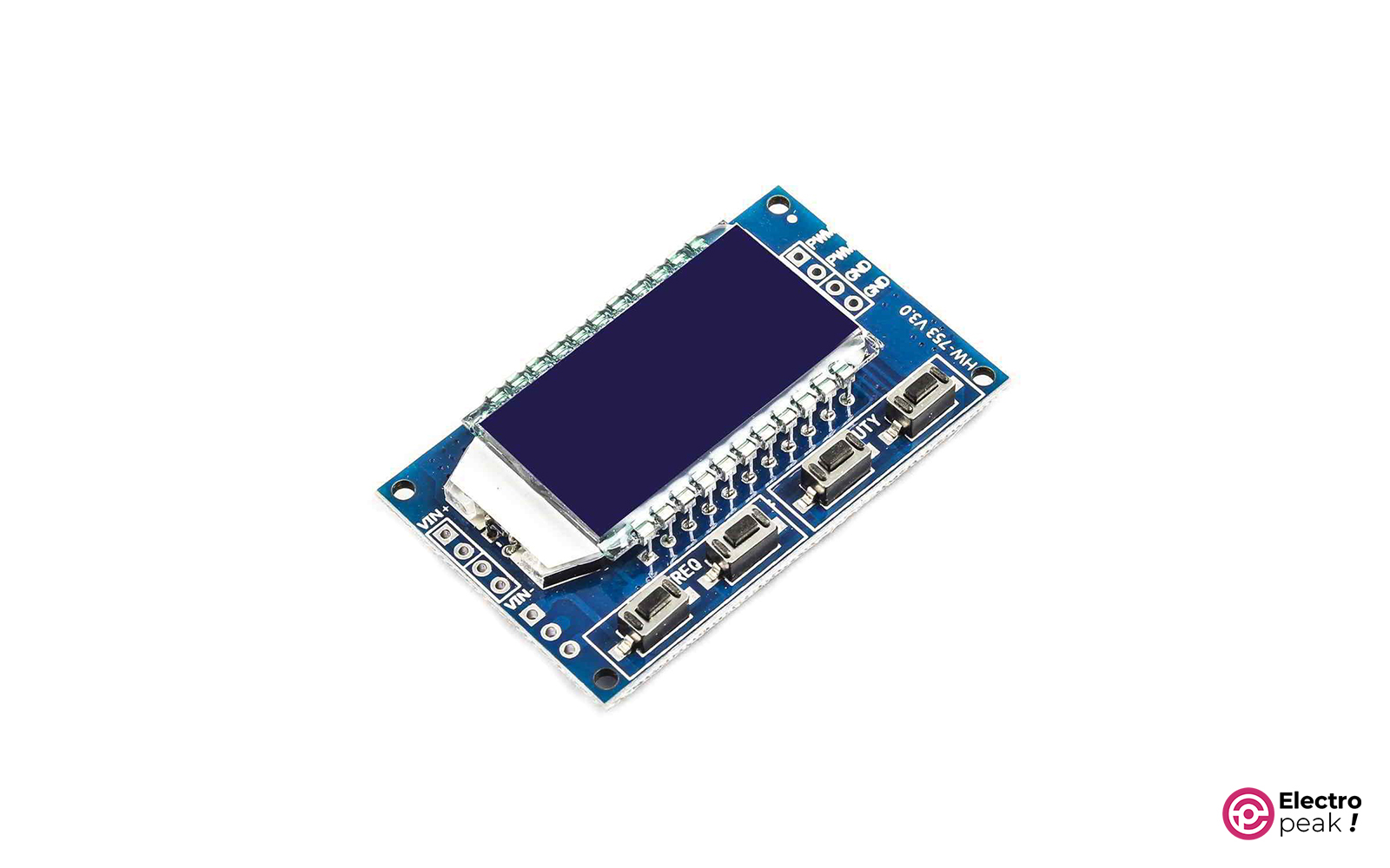
Устройство представляет собой плату, на одной стороне которой расположены контакты для подключения, LCD-дисплей и четыре группы микровыключателей для управления настройками. С другой стороны – распаяна электронная схема с микроконтроллерами и прочими элементами. Корпус отсутствует. Для установки платы в коробку или на панель предусмотрено четыре монтажных отверстия по углам.
Подключение входных и выходных сигналов выполняется с помощью пайки. Все контакты и кнопки подписаны и удобно объединены в группы прямоугольной маркировкой. Электронные компоненты впаяны в плату аккуратно и надежно. При должной эксплуатации устройство прослужит вам много дольше 12-месячного гарантийного срока.
Особенности
Главным преимуществом модели xy lpwm является наличие трех выходных каналов. Это очень удобно и позволяет тестировать сразу несколько аудиоустройств. Прибор работает в частотном диапазоне от 1 до 150 000 Гц.
Из других эксплуатационных преимуществ следует выделить высокую точность генерации:
- для рабочего цикла – не более 1 %;
- для частоты – не более 2 %.
Включение происходит при подаче напряжения от 3,3 до 30 В. От конкретного значения входного питания зависит максимальная амплитуда на выходе. Выходной ток на генераторе не очень высокий и составляет максимум 30 мА. Поэтому для проверки мощных потребителей необходимо использовать более мощные выходные транзисторы.
Инструкция для xy lpwm
На небольшом цифровом экране LCD-типа располагается информация о параметрах формируемого сигнала. Интерфейс двухстрочный. На верхней строке находится значение частоты, чтобы изменить его, необходимо использовать группу переключателей FREQ. На нижней выводится уставка по скважности с маркировкой соответствующего канала d1, d2 или d3. Для изменения этих параметров предусмотрены микропереключатели DUTY 1, 2 и 3.

Технические характеристики, внешний вид и комплектация
товара
могут быть изменены
производителем без предварительного уведомления.

Одноканальный импульсный генератор XY-LPWM с LCD дисплеем.

- Комментарии
- Информация
-
-
sova
Модуль XY-LPWM регулируемого импульсного генератора, построен на базе трех микросхем.
1. Микросхема N76E003AT20 — 8-bit микроконтроллер или аналог STM8S003F3Pb;
2. Микросхема HT1621B — Контроллер для LCD дисплея;
3. Микросхема HM5333B – Линейный стабилизатор на 3.3В.— Питание модуля (Vin) осуществляется от источника питания в пределах 3.3В до 30В
— Диапазон регулирования частоты от 1Гц до 150кГц, который разбит на четыре поддиапазона:
Первый — 1Гц-999Гц с шагом 1Гц;
Второй — 1кГц-9.99кГц с шагом 0.01кГц
Третий — 10кГц-99.9 кГц с шагом 0.1кГц
Четвертый — 100кГц-150кГц с шагом 1кГц
— Точность в каждом диапазоне составляет около 2%
— Коэффициент заполнения сигнала изменяется от 0 до 100%
— Выходной ток ГИ может составлять около 5-30 мА
— Амплитуда выходного сигнала равна питанию модуля. Например, на ГИ мы подали питание 12В, соответственно амплитуда выходного сигнала будет также 12В.
— Модуль XY-LPWM управляется как вручную, с помощью кнопок FREG и DUTY, так и через компьютер, подсоединив его к TTL последовательному порту (TXD, RXD, GND).
Команда «read» — это считывание настроек (F и D);
команда «DXXX» — изменение коэффициент заполнения сигнала (XXX от 001 до 100);
команда «F101» установка частоты 101Гц(от 001 до 999), «F1.05» установка частоты 1.05кГц(1.00-9.99), «F10.5» установка частоты 10,5КГц(10.0-99.9), «F1.0.5» установка частоты 105кГц(1.0.0-1.5.0)
Пока нет ни одного комментария. -
-
- Из альбомов:
- Управление шаговым двигателем.
- Добавил(а):
- sova
- Дата:
- 4 апр 2018
- Просмотры:
- 9.774
- Количество комментариев:
- 1
Данные EXIF
- File Size:
-
64,6 КБ
- Mime Type:
-
image/jpeg
- Width:
-
432px
- Height:
-
900px
Примечание: данные EXIF будут сохранены на корректных типах файлов при загрузке фото. Фото может потом пройти ряд манипуляций (поворот, отражение, обрезка и т.д. и т.п.)

-
Robotics
-
Written by
Ali Akbar Hosseini

Table of Contents
Introduction
You must have come across the terms “square pulse generation” and “pulse width modulation” (or PWM), and you probably have worked with them—for example, which pins of Arduino (or any other microcontroller) can generate PWM pulses. Pulse width modulation is a technique for generating square pulse signals with desired features, which are widely used in different areas of Electronics. Some of these applications include controlling the color and brightness of LEDs, controlling engines and timers, and synchronizing digital systems. This technique is also used in almost all switching power supplies and other methods for controlling the voltage or power.
Due to the importance of this concept, first, we will briefly explain it.
What is PWM?
PWM (or Pulse Width Modulation) is a process through which we control and adjust the parameters of a square waveform. The most important parameters include frequency, duty cycle, and voltage amplitude.
Consider the figure below:
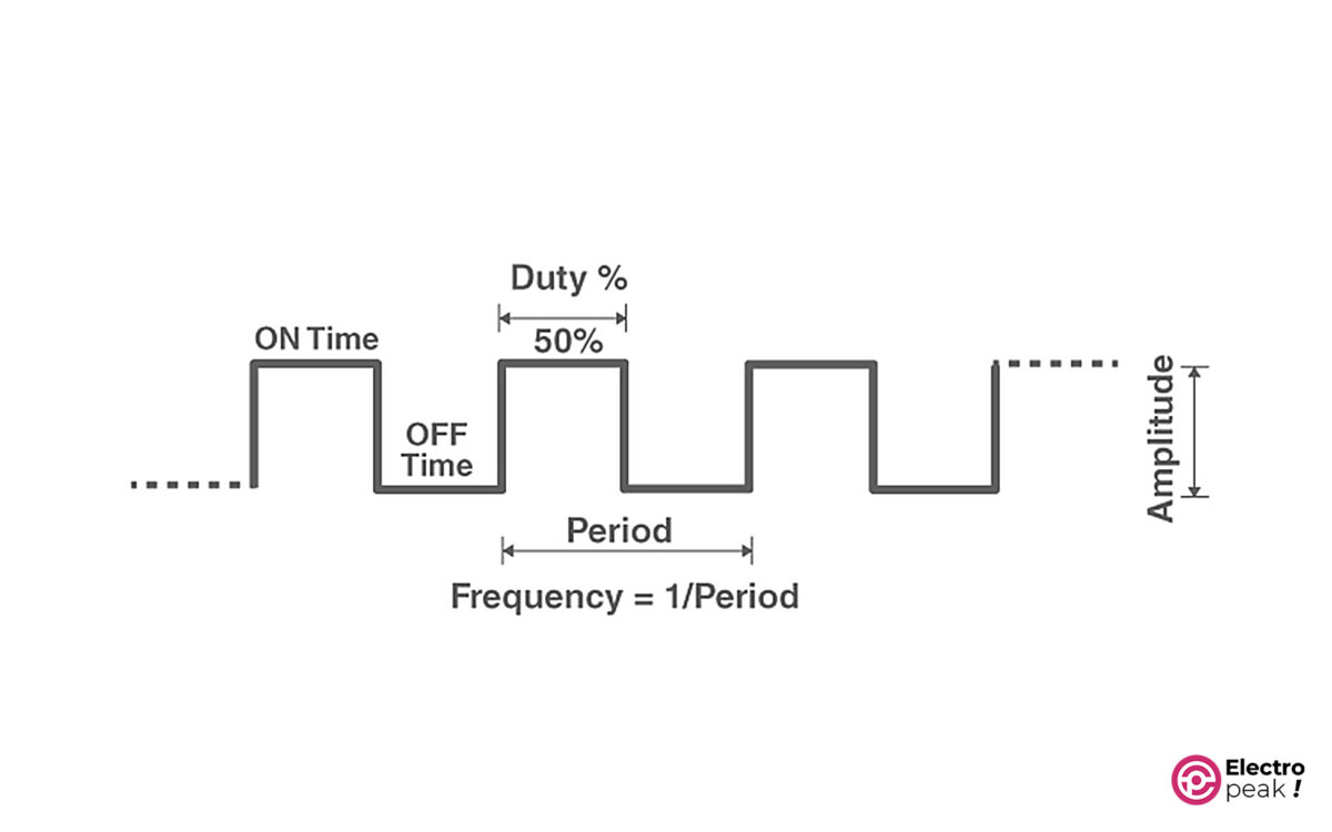
Here are the main parameters of a square waveform:
Period: The time taken for one cycle of the waveform. Its symbol is T, with a unit of “second.”
Frequency: The inverse of period. In other words, frequency is the number of periods per second. Its symbol is “f,” with a unit of Hz (1Hz=1/1s).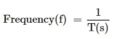
Duty Cycle: The ratio of on-time to the period. And it is usually represented in a percentage. 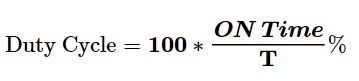
Amplitude: voltage amplitude.
Example: We have a voltage waveform that is on for 1.2 seconds and off for 0.8 seconds. And this process is repeated every 2 seconds. Find the frequency and duty cycle of the waveform.
Simple, isn’t it? Since the process is repeated every 2 seconds, the period would be 2 seconds.
Frequency = 1/2 = 0.5 Hz.
Duty Cycle: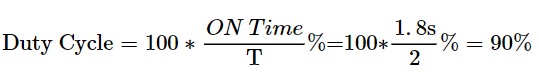
In this tutorial, we will not provide a complete explanation of the PWM concept and the related methods and applications. Therefore, the introduction above is necessary and perhaps enough for our purposes. You can refer to the numerous articles about this topic if you need more information.
Various modules and components have been designed and manufactured to generate PWM signals with different methods. In this tutorial, we will learn how to use the XY-LPWM module, which is almost a complete and well-equipped component for our purpose.
XY-LPWM PWM Signal Generator Module Features
XY-LPWM is a square pulse generator module that has more features compared to many other modules in this family. The output frequency of the module ranges from 0 Hz to 150 KHz, and you can adjust the duty cycle from 0 to 100%. In addition, the accuracy of the output frequency is 2% which is considered a great accuracy for many applications.
It is very easy to work with the XY-LPWM module due to the one LCD and four push buttons to adjust the frequency and duty cycle independently. In addition, the TTL serial user interface is designed on the module, by which we can communicate with the module through the serial port of a computer.
The input voltage is between 3.3 to 30 DC volts. The voltage amplitude of the output pulse is also generated without any drop compared to the input voltage amplitude.
XY-LPWM Specifications
• Input voltage: 3.3 to 30 volts
• Current consumption of module: 20mA (at 5V power supply)
• Output voltage amplitude: equals to the input voltage amplitude
• Frequency: 0 Hz to 150 KHz
• Frequency Accuracy: around 2%
• Duty cycle: 0 to 100%
• Maximum output current: 30 mA
• Operating temperature: -20 to 70 °C
• An LCD screen to display the frequency and duty cycle of the generated wave
• TTL Serial Interface with a 3.3V logic level
• Dimensions: 52*32*10 mm
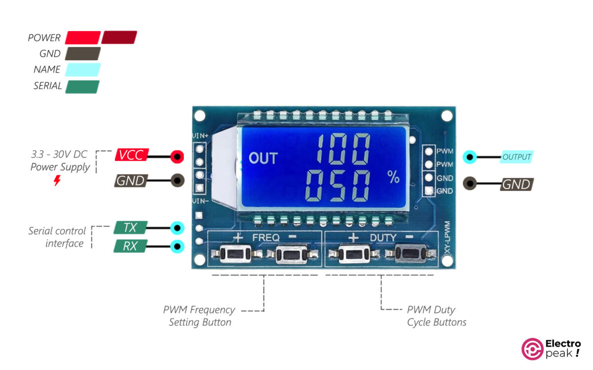
XY-LPWM Pinout
• VIN+: power supply of module (input voltage)
• GND: ground
• VIN-: ground
• PWM: output pin of pulse
Serial communication pins:
• TXD: transmit data pin
• RXD: receive data pin
Required Materials

Hardware Components
| PWM Signal Generator Module with a Digital Display | × | 1 | |
| PWM Switch Module* | × | 1 | |
| 12V Fan** | × | 1 | |
| Jumper Wire | × | 1 | |
| 5 to 12V Power Supply | × | 1 |
*: We use PWM Switch Module to increase the module’s output power. And there are many similar items for it in the market. Of course, you don’t need to buy this module if you are looking for a low-power output.
**: The 12V fan also tests and simulates the engine speed control. You don’t need this component for other purposes.
How to Use XY-LPWM Digital Pulse Generator Module
Module’s Power Supply
You should use this module within a voltage range of 3 to 30 volts which are supplied by the VIN+ pins. The two VIN+ pins are internally connected, so all you have to do is connect one to the power supply’s positive pin. The same applies to the VIN- pins connected to the circuit GND.
The power input of the module is protected by a Schottky diode against high voltages. In addition, the logic circuit of the module works with a voltage level of 3.3 which is provided by a 3.3V regulator on the board.
Note
Unlike many pulse generator modules, the module’s output voltage has no drop compared to the input voltage. Therefore, the output voltage amplitude equals the input voltage amplitude.
When the output voltage goes below 4V, the screen backlight decreases. The module, however, functions properly even at voltages as low as 3V.
The module draws 20mA from the power supply at operating voltages lower than or equal to 5V. In other words, the power consumption at an operating voltage of 5V is about 0.1 w.
Warning
The power mentioned above is the module’s operating power which is not the same as the module’s output power. In addition, the power supply must be able to support both of them.
For example, at an operating voltage of 5V, the maximum total power consumption is equal to the sum of the following powers:
Module’s power consumption= operating voltage * module’s current consumption= 20mA * 5V = 0.1 w,
Output power = output voltage * output current = 30mA * 5V = 0.15 w.
The power supply, therefore, must provide at least 0.25 w of power, i.e. it must provide at least 50mA at an operating voltage of 5V.
Initial Test of XY-LPWM PWM Signal Generator Module
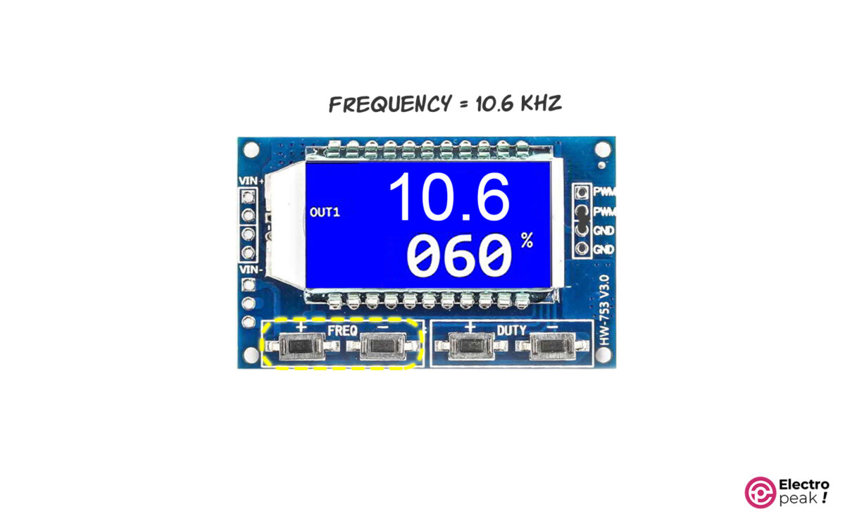
For a simple test on XY-LPWM module, connect the wires as shown below. The power supply voltage must be between 3.3 to 30 volts.

You can see the general screen format in the image above. The first line is the output pulse frequency, and the second line shows the duty cycle percentage of the output pulse signal.
Warning
In some models of XY-LPWM modules, the output duty cycle percentage is complementary to the duty cycle displayed on the screen. For example, if it shows 60%, the output duty cycle is in fact 40%. In practice, though, this won’t be a problem because you can adjust its complementary to have the desired duty cycle.
You can observe the module output with an oscilloscope to make sure that you’ve got the desired output frequency and duty cycle.
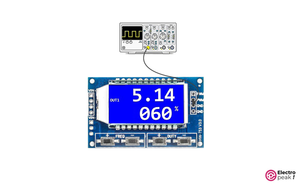
The waveform frequency on the oscilloscope must be equal to the frequency shown on the module screen.
Solution for Output Current Limitation in XY-LPWM Pulse Generator Module
As mentioned, the maximum output current of the XY-LPWM module is 30mA. This current will work perfectly well when using logic circuits because they don’t need a lot of current. But 30mA won’t be nearly enough when running a device such as a DC motor. For such cases, we have to amplify the output current.
One way to increase the output current and power is to use switching circuits. In this method, we use the output signal of the XY-LPWM module as the excitation signal for the switching circuits. Therefore, we can use the switching circuit output to run high-power devices.
There are colorful switching circuits, and most of them are designed based on transistors. Using these circuits, we can run and control an actuator such as a motor (which has a high amount of voltage and current) by a weak excitation signal (which has a low amount of voltage and current). We can get the excitation signal from a microcontroller or any other circuit, such as the XY-LPWM module.
First, let’s briefly explain one type of switching circuit that has a MOSFET transistor.
MOSFET as Switch
The circuit below shows the general form of using a MOSFET in a switching circuit.
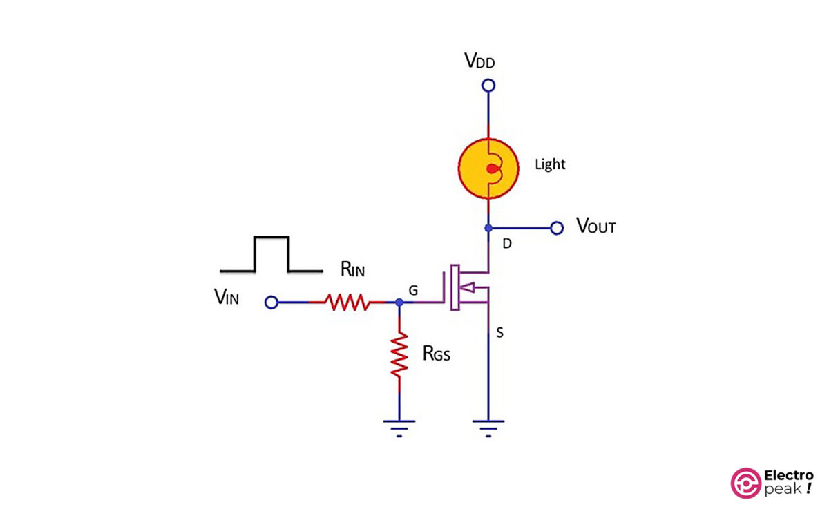
In the above circuit, as the input voltage (VIN) goes up, so does the voltage of the transistor’s gate pin (G). This will activate the transistor, which means, now, there is a connection between the drain pin (D) and the source pin (S), and the current can flow from VDD to GND. As a result, we can turn on a light (or any consumer) in the circuit.
To provide the required excitation signal for the transistor, we should connect the VIN pin to a microcontroller or a circuit. By doing so, the current consumed by the consumer will no longer pass through the VIN pin. In addition, the VDD value, which works as the power supply for the consumer, can be much higher than the excitation voltage. (The voltage and current of “Drain-Source” and “excitation signal” are different in various transistors. So if you need the exact specs of each specific model, you should see their datasheet.)
For example, let’s control a 12V motor with Arduino. Since the voltage of Arduino pins is 5V and their current can be 30mA at most, we can’t connect the Arduino pins, as an output, directly to the motor pin. Solution: The above switching circuit. All you have to do is connect the Arduino’s output pin to VIN, and VDD to the 12V power supply and then replace the light with a motor. In this case, we can activate the power supply circuit of the 12V motor with the Arduino’s 5V signal. Now, we control the speed of a DC motor with a power-switching module.
In this example, we use the HW-517 MOSFET Switching Module as the switching circuit. This module has two AOD4184A Power MOSFETs in parallel, which can provide 15A. In addition, the excitation voltage of the HW-517 module is between 3.3 to 20V, and the output voltage can range from 5 to 36V.
Motor Speed Control by XY-LWPM Pulse Generator Module and MOSFET Switch
Wiring
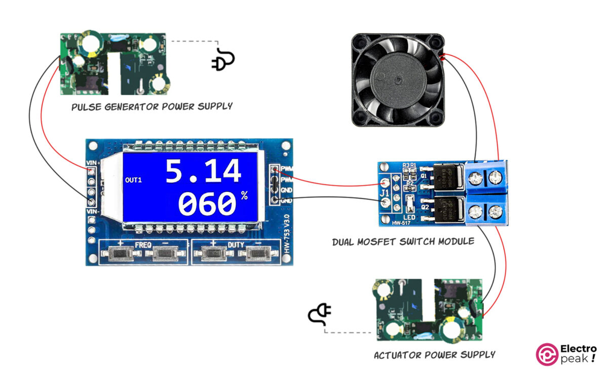
In the above circuit, the output of the XY-LPWM module is given to the switching module as the excitation signal. The MOSFETs are switched on and off with the same frequency and duty cycle as the excitation signal. As a result, the connection between the fan and the power supply on the right side is switched on and off. This way, we can control the average voltage given to the fan by controlling the frequency and duty cycle. In addition, the DC motor speed is proportional to the average voltage.
Tip
Since the excitation voltage of the MOSFET module is between 3.3 to 20 volts, the output voltage of the pulse generator must also be within the same range. Therefore, the voltage of the pulse generator’s power supply must range from 3.3 to 20 volts.
The power supply on the right side should have a voltage value between 5 to 36 volts; its exact value is determined by the consumer’s operating voltage (here, the fan). Also, we should choose the power supply current according to the actuator current.
If the actuator voltage is between 5 to 20 volts, we can use a typical power supply as long as it can provide the required total current.
We can also use the above circuit to control the color and brightness of RGB LEDs.
XY-LPWM Pulse Generator Module Configuration
Frequency Settings
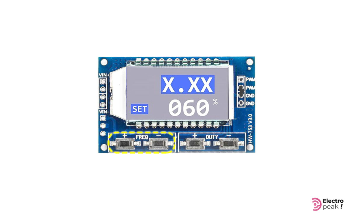
You can adjust the module frequency from 0 Hz to 150 KHz. To do that, simply press the buttons related to frequency adjustment—the “+” button for increasing the frequency and the “-“ button for decreasing it. Remember that the frequency changes more quickly if you press and hold the buttons.
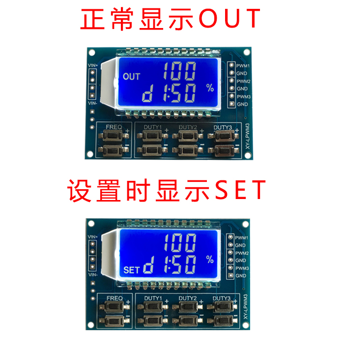
When you are changing the frequency, the word “OUT” disappears, and then the word “SET” appears on the screen. The value related to the frequency also changes on the screen (in the first line).
Here are the formats to display the frequency value:
XXX: In this format, the value is the output frequency represented in Hz. And it ranges from 0 to 999Hz. For example, when you see “300” on the screen, it means 300Hz.

X.XX: The value is represented in “KHz,” and it ranges from 1KHz to 9.99KHz. For example, when you see “1.00” on the screen, it means 1KHz. In addition, whenever you press the related buttons, the frequency changes by 10Hz.

XX.X: The value is represented in tens of KHz, and it ranges from 10.0KHz to 99.9KHz. For example, when you see “10.0” on the screen, it means 10KHz. In addition, whenever you press the related buttons, the frequency changes by 100Hz.
X.X.X: The value is represented in hundreds of KHz, and it ranges from 100KHz to 150KHz. For example, when you see “1.0.0” on the screen, it means 100KHz. In addition, whenever you press the related buttons, the frequency changes by 1KHz.

Duty Cycle Settings
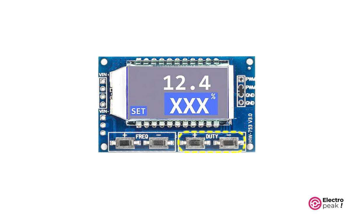
The module’s duty cycle ranges from 0 to 100%. To adjust this parameter, you can press the buttons “+” and “-“ shown in the image above. In addition, the three-digit number on the second line of the screen represents this parameter.
Controlling XY-LPWM Pulse Generator Module with Serial Interface
As mentioned, the module has a serial interface port with a 3.3V logic level. We can adjust the frequency features of the generated wave or restore the adjusted features by some specific commands using the serial port.
If you are using a 5V logic-level microcontroller to communicate with the module, make sure to use a voltage-level converter so as not to damage the pulse generator module.
The serial communication baud rate is 9600.
Frequency Settings
To adjust the frequency, send the data—in a similar format as in the display with an “F” prefix—to the module via the serial interface. Look at the examples below:
• F100: Adjusting the frequency to 100Hz
• F1.00: Adjusting the frequency to 1kHz
• F10.0: Adjusting the frequency to 10kHz
• F1.0.0: Adjusting the frequency to 100kHz
If the module understands the message, it will respond with the word “DOWN”. Otherwise, it will show the word “FAIL.”
Duty Cycle Settings
To adjust the duty cycle, send it to the module with a “D” prefix. Here’s an example:
D050: Adjusting the duty cycle to 50%.
Value Reading
You should send the word “read” to the module to read the module settings.
What’s Next?
With three XY-LPWM modules and three switch modules, as in the second example, build an RGB color controller and adjust the color and brightness of an RGB LED String.
Build a digital-to-analog converter using a pulse generator module and an RC circuit.
Using Arduino, write a code that can both receive the values from the serial port of a computer and then apply it to the module.
Liked What you see?
Get updates and learn from the best
More To Explore
Comments (2)
-
Ajay Shee
Reply
Nicely Explained
August 29, 2023 at 6:55 am
-
Ajay Shee
Reply
Nicely Explained
August 29, 2023 at 6:55 am
-
Mohammad Damirchi
Reply
you’re welcome
August 30, 2023 at 5:31 am
-
-


Leave a Reply
- 185 Reviews
- 3 Questions
- Category: Signal Generators >>>
- Supplier: Shenzhen,Ruised,Technology,Co.,Ltd.
Product Overview
Description
XY-LPWM3 DC3.3-30V 3 Channel Frequency 1Hz-150KHz Duty Cycle 0 -100 Adjustable Meter PWM Signal Generator with LCD Display Meter
Product Description
Module Features:
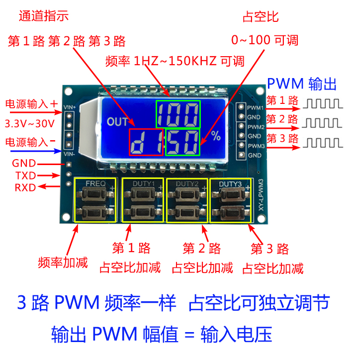
- Output of three-channel PWM at the same time, Adjustable frequency, 3-channel frequency output consistent, duty ratio can be independently adjusted, suitable for most occasions
- Lcd can display frequency and duty datio,Easy to oprate;
3. Wide frequency range, high precision;
4. Support Serial operation
1,Module description
Three-channel PWM is outputted,wide frequency range and the duty ratio can be adjusted independently;
Frequency is divided into four areas, automatic switching:
- XXX(No decimal point): 1HZ Stepping Unit, Range: 1Hz~999Hz;
- X.XX(The decimal is in the hundreds place):0.01KHZ Stepping Unit, Range: 1.00Khz~9.99Khz;
- X.XX(The decimal is in the tens place):0.1KHZ Stepping Unit, Range: 10.0Khz~99.9Khz;
- X.X.X(The decimal is in the ones place): 1KHZ Stepping Unit, Range: 1Khz~150Khz;
e.g. ,frequency display:100 represent the pulse of 100Hz ;
1.01 represent the pulse of 1.01KHz;
54.1 represent the pulse of 54.1KHz
1.2.4 represent the pulse of 124Hz
- The value range of dutyfactor: 0~100%,100% is represented by A0%.
All parameters setted up can be automatically saved in case of power cut.
2,Parameter settings
Module has 8 independent keys, used to set the frequency and duty ratio, support short press (increase or decrease a unit) and long press (fast increase or decrease), very simple, set the parameters automatically save, power loss.
3-Way duty ratio button can be pressed at the same time, real-time adjustment, liquid crystal display is the last pressed button duty ratio, real-time is very strong, can be used as a simple several road duty ratio scan.
3,Module Parameters:
1.Operating voltage:3.3~30V;
2. Frequency range:1Hz~150KHz;
3. Frequency accuracy: In each range of accuracy is about 2%
4. Signal load capacity: Output current can be around 5~30ma
5. Output amplitude: PWM amplitude and supply voltage equal
6. Ambient temperature:-20~+70°C.
4,Scope of application:
1. Used as square wave signal generator to generate square wave signal for experiment development and use
2. Used to generate a square wave signal to control the motor driver;
3. Generating adjustable pulses for MCU use;
4. Generate adjustable pulse, control related circuit (PWM dimming speed and other applications).
5,UART Serial command
Baud rate:9600 bps Data length:8
Stop bits :1
Check digit:none
Flow control:none
- set the frequency of the PWM
«F101»: Set frequency of 101 HZ (001~999)
«F1.05»: Set frequency of 1.05 KHZ (1.00~9.99)
«F10.5»: Set frequency of 10.5KHZ (10.0~99.9)
«F1.0.5»:Set frequency of 105KHZ (1.0.0~1.5.0)
- set the duty ratio of PWM
«DX:YYY»: Set PWM duty ratio x: (1~3) PWM serial number, YYY: (000~100) duty ratio;
For example d1:050, set 1th PWM duty ratio to 50%
- Read Setup parameters
Send a «read» string to read the parameters of the setting.
Message format:F156,D1:052,D2:059,D3:058,
Set successful return:DOWN
Set failed to return:FALL
Packaging & Shipping
We offer two kinds of shipping methods:
1.Economy Shipping way (China post air mail)
Tracking website: http://www.17track.net/en
|
Area |
Normally delivery time |
Basic 0.1KG |
Extend 0.1KG |
|
Asia |
15 to 60 working days |
6.00 USD |
2.00 USD |
|
USA,Canada,Australia |
15 to 60 working days |
6.00 USD |
2.50 USD |
|
Europe |
15 to 60 working days |
6.00 USD |
2.50 USD |
|
Others |
20 to 65 working days |
7.00 USD |
3.00 USD |
2.Expedited Int’l Shipping (FEDEX, DHL, TNT, EMS)
According to different countries and regions your address maybe remote area, we have the right to charge an additional remote cost below:
UPS: https://www.ups.com/cn/en/Home.page
DHL: http://www.cn.dhl.com/en.html
Fedex: https://www.fedex.com/en-us/home.html
TNT: https://www.tnt.com/express/en_cn/site/home.html
Delivery time
For expecial countries TNT, EMS will spend 10-15 working days.
|
Area |
Normally delivery time |
Basic 0.5KG |
Extend 0.5KG |
|
Asia |
3 to 7 working days |
18.00 to 22.00 USD |
5.00 to 8.50 USD |
|
USA,Canada,Australia |
3 to 8 working days |
20.00 to 25.00 USD |
6.00 to 7.50 USD |
|
Europe |
3 to 8 working days |
20.00 USD |
6.00 USD |
|
Others |
5 to 15 working days |
35.00 USD |
12.00 USD |

Our Services
Ruised offers one stop service for Modules and all kinds of electronic components( ICs, Diodes, Transistors, Optocouplers, Capacitors, Resistors, MOSFET, Crystal, Fuses, Connectors, Switches, Adaptors, Potentiometers, etc..)
We only sell the original new items!
Best Quality Assurance:
1. We only provide the original new items, 100% make sure the best quality!
2. 60-days GUARRANTEE OF QUALITY (After Our Delivery Date).
Payment Methods :
We accept T/T, West Union, PayPal,Alibaba’s online trade assurance,Escrow payment .
Refound or Replacement:
We accept return back itmes if the goods still remain in their original condition on the warrant time!
FAQ
Q1. What is your terms of packing?
A: Generally, we pack our goods in neutral white boxes and brown cartons. If you have legally registered patent,
we can pack the goods in your branded boxes after getting your authorization letters.
Q2. What is your terms of payment?
A: Full payment. Goods would be shipped in 3-5 work days after payment received, finally depends on quantities.
Q3. What is your terms of delivery?
A: EXW.
Q4. How about your delivery time?
A: Generally, goods would be shipped in 3-5 work days after payment received, finally depends on order quantities.
Q5. What is your sample policy?
A: We can supply the sample if we have ready parts in stock, but the customers have to pay the sample cost and
the courier cost.
Q6. Do you test all your goods before delivery?
A: Yes, we have 100% test before delivery
Q7: How do you make our business long-term and good relationship?
A:1. We keep good quality and competitive price to ensure our customers benefit ;
2. We respect every customer as our friend and we sincerely do business and make friends with them,
no matter where they come from.
Company Information
Shenzhen Ruised Technology Co., Ltd. is a professional Electronic component Manufacturer, which have over 8 year business experience.
We specialize in the production of Modules and Electronic Components, IC Chips, Transistors, Diodes, Triodes, Rectifiers, Sensors, Thyristors, TACT switches, Connectors, Resistors and Capacitors, with well-equipped testing equipment and strong technical force. With a wide range good quality, reasonable prices and fast delivery, our products are extensively used in Civilian equipment, Military industry, Industrial Equipment and other industries.
All of our products come from original famous manufacturers with complete warranty. Our products are widely recognized and trusted by users and can meet continuously developing economic and social needs. This also enables us to gain support and trust from our consumers. Besides, we have established long-term stable and cooperative relationships with a number of retailers and agents. This has helped us succeed in the fierce IC line. We have become the first choice for many customers.
Our advantage:
1.More than 1000,000 own stock inventory to meet your needs of different products.
We specialize in various types of Modules.Active electronic components(Integrated Circuits, , Relay, Sensors, and etc)and Passive electronic components (Filter, Magnetic Bead.Diodes, Transistors, Capacitors, Resistors, Inductors, and etc) over 10 years.
2. Competitive priceadvantage helps tosave your purchase cost and your precious time.
We wholesale and distribute new,original &famous brand Electronic Components all over the world.
3.Own the international advanced testing equipment of electronic components and scientific storage system to ensure the quality stability.
4.Excellent elite team, more than 6 years seniority, and a good understanding of international market trends.
Factory show:
Warehouse show:

Office show:

Contact
Compnay:Shenzhen Ruised Technology Co., Ltd
Address: A building,Huaqiang Plaza,Futian District, Shenzhen,GuangDong,518031 China
Email: Errica@ ruised.com
Phone: 86-0755-82733663
Website: https://ruised.en.alibaba.com
We Recommend
3 канала с цифровым дисплеем ШИМ-частота импульсов, прямоугольная волна, модуль генератора сигналов прямоугольной формы с регулируемым рабочим циклом
3- КАНАЛЬНЫЙ ШИМ-ИМПУЛЬСНЫЙ МОДУЛЬ С РЕГУЛИРУЕМЫМ РАБОЧИМ ЦИКЛОМ, ГЕНЕРАТОР ПРЯМОУГОЛЬНЫХ СИГНАЛОВ ПРЯМОУГОЛЬНОЙ ВОЛНЫ
Основные моменты модуля:
1. 3 канала выхода PWM , регулируемая частота, 3 канала частотного выхода, рабочий цикл можно регулировать независимо, подходит для большинства случаев;
2. Частота ЖК- дисплея и рабочий цикл очень четкие и легко настраиваются.
3. Широкий частотный диапазон и высокая точность;
4. Возможна последовательная связь.
1. Описание модуля
3- полосный выход PWM , широкий частотный диапазон, рабочий цикл можно независимо регулировать в реальном времени;
Частота разделена на четыре диапазона, которые переключаются автоматически:
1. XXX ( без десятичной точки ) : наименьшая единица — 1 Гц , диапазон значений — 1 Гц ~ 999 Гц ;
2. Наименьшая единица измерения X.XX (десятичная точка — сотни) составляет 0,01 кГц , а диапазон значений составляет 1,00 кГц ~ 9,99 кГц ;
3. XX.X ( десятичная точка находится в разряде десятков ) : наименьшая единица измерения — 0,1 кГц ; диапазон значений — 10,0 кГц ~ 99,9 кГц.
4. XXX ( десятичная точка в десятках и сотнях ) : наименьшая единица измерения — 1 кГц ; диапазон значений — от 1 кГц до 150 кГц.
например, отображение частоты: 100 означает выход ШИМ, импульс 100 Гц ;
1.01 означает, что PWM выводит 1.01K импульсов;
54.1 означает, что ШИМ выдает импульс 54,1 кГц ;
1.2.4 представляет выходной импульс ШИМ 124 кГц ;
Диапазон значений рабочего цикла: 0 ~ 100% , где 100% представлено A0% .
Все параметры настройки сохраняются после отключения питания.
2. Настройка параметров
Модуль имеет 8 независимых кнопок для установки частоты и рабочего цикла. Он поддерживает короткое нажатие (увеличение или уменьшение на одну единицу) и долгое нажатие (быстрое увеличение или уменьшение). Это очень просто. Параметры автоматически сохраняются после настройки. .
3- канальные кнопки рабочего цикла могут быть нажаты одновременно для настройки в реальном времени. На ЖК-дисплее отображается рабочий цикл последней нажатой кнопки. Производительность в реальном времени очень высока, и его можно использовать как простой режим. циклическое сканирование нескольких каналов.
3. Параметры модуля:
1. Рабочее напряжение: 3,3 ~ 30 В ;
2. Частотный диапазон: 1 Гц ~ 150 кГц ;
3. Точность частоты: точность в каждом диапазоне около 2% ;
4. Нагрузочная способность сигнала: выходной ток может составлять около 5 ~ 30 мА ;
5. Амплитуда выходного сигнала: амплитуда ШИМ равна напряжению источника питания;
6. Температура окружающей среды: -20 ~ + 70 ℃.
4. Сфера применения:
1. Используется в качестве генератора прямоугольных сигналов для генерации прямоугольных сигналов для экспериментальной разработки и использования;
2. Используется для генерации прямоугольного сигнала для управления приводом двигателя;
3. Генерировать регулируемые импульсы для использования MCU ;
4. Создавайте регулируемые импульсы и схемы, связанные с управлением ( например, ШИМ- регулировка яркости и регулировка скорости).
5. Управление последовательным портом (однокристальная связь уровня TTL )
Стандарт связи : 9600 бит / с Бит данных : 8
стоповых бит : 1
контрольный бит : нет
Управление потоком : нет
1. Установите частоту ШИМ.
«F101»: установите частоту 101 Гц (001 ~ 999)
«F1.05»: установите частоту 1,05 кГц (1,00 ~ 9,99).
« F10.5 »: установите частоту 10,5 кГц (10,0 ~ 99,9)
«F1.0.5»: установите частоту 105 кГц (1.0.0 ~ 1.5.0)
2. Установите рабочий цикл ШИМ.
«Dx: yyy»: установить рабочий цикл ШИМ x: ( 1 ~ 3 ) Серийный номер ШИМ , yyy: ( 000 ~ 100 ) Рабочий цикл % ;
Например , Dl: 050 , установить первый один -ходовой PWM рабочий цикл 50%
3. Прочтите параметры настройки.
Отправьте строку « read », чтобы прочитать установленные параметры.
Формат считываемых данных следующий: F156 , D1 : 052 , D2 : 059 , D3 : 058 ,
Установить успешный возврат: ВНИЗ ;
Если настройка не удалась, верните: ПАДЕНИЕ .
Для покупки товара в нашем интернет-магазине выберите понравившийся товар и добавьте его в корзину. Далее перейдите в Корзину и нажмите на «Оформить заказ» или «Быстрый заказ».
Когда оформляете быстрый заказ, напишите ФИО, телефон и e-mail Вам перезвонит менеджер и уточнит условия заказа. По результатам разговора вам придет подтверждение оформления товара на почту. Теперь останется только ждать доставки и радоваться новой покупке.
Оформление заказа в стандартном режиме выглядит следующим образом. Заполняете полностью форму по последовательным этапам: адрес, способ доставки, оплаты, данные о себе. Советуем в комментарии к заказу написать информацию, которая поможет курьеру вас найти. Нажмите кнопку «Оформить заказ».
Оплачивайте покупки удобным способом. В интернет-магазине доступно 2 варианта оплаты:
- Наличные при самовывозе или доставке курьером. Специалист свяжется с вами в день доставки, чтобы уточнить время и заранее подготовить сдачу с любой купюры. Вы подписываете товаросопроводительные документы, вносите денежные средства, получаете товар и чек.
- Безналичный расчет при самовывозе или оформлении в интернет-магазине: карты Visa и MasterCard. Чтобы оплатить покупку, система перенаправит вас на сервер системы ASSIST. Здесь нужно ввести номер карты, срок действия и имя держателя.
Экономьте время на получении заказа. В интернет-магазине доступно 4 варианта доставки:
- Курьерская доставка работает с 10.00 до 19.00. Когда товар поступит на склад, курьерская служба свяжется для уточнения деталей. Специалист предложит выбрать удобное время доставки и уточнит адрес. Осмотрите упаковку на целостность и соответствие указанной комплектации.
- Самовывоз из магазина. Когда заказ поступит на склад, вам придет уведомление. Для получения заказа обратитесь к сотруднику и назовите номер.
- СДЭК. Вы получите уведомление о готовности Вашего заказа от транспортной компании. Срок хранения — 14 дней.
- Почтовая доставка через почту России. Когда заказ придет в отделение, на ваш адрес придет извещение о посылке.