Найдите нужную инструкцию или руководство на нашем сайте
Gw instek sps 3610 инструкция
Изображения служат только для ознакомления, см. техническую документацию
6 000 руб.
× 1 = 6 000 руб.
Добавить в корзину 1шт.
на сумму 36 900 руб.
Номенклатурный номер:60689
Артикул:SPS-3610
Бренд / Производитель: GW Instek
Описание
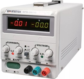
Характеристики: 36 В, 10 А (100 мВ, 10 мА) Цифровая индикация тока и напряжения, Высокий КПД; Высокая стабильность и малый уровень пульсаций; Плавная регулировка выходных параметров ГРУБО/ТОЧНО; Режимы стабилизации тока и напряжения; Установка предела по току; Защита от переполюсовки и перегрузки, масса 3,3 кг
Посмотреть инструкция для GW Instek SPS-3610 бесплатно. Руководство относится к категории Без категории, 1 человек(а) дали ему среднюю оценку 6.9. Руководство доступно на следующих языках: английский. У вас есть вопрос о GW Instek SPS-3610 или вам нужна помощь? Задайте свой вопрос здесь
Не можете найти ответ на свой вопрос в руководстве? Вы можете найти ответ на свой вопрос ниже, в разделе часто задаваемых вопросов о GW Instek SPS-3610.
Инструкция GW Instek SPS-3610 доступно в русский?
Не нашли свой вопрос? Задайте свой вопрос здесь
* Изображения служат только для ознакомления, см. техническую документацию
от 2 шт. — 36 700 руб.
от 8 шт. — по запросу
6 000 руб.
× 1 = 6 000 руб.
Добавить в корзину 1шт.
на сумму 36 900 руб.
Номенклатурный номер:60689
Артикул:SPS-3610
Страна происхождения:КИТАЙ
Бренд / Производитель: GW Instek
Описание
Характеристики: 36 В, 10 А (100 мВ, 10 мА) Цифровая индикация тока и напряжения, Высокий КПД; Высокая стабильность и малый уровень пульсаций; Плавная регулировка выходных параметров ГРУБО/ТОЧНО; Режимы стабилизации тока и напряжения; Установка предела по току; Защита от переполюсовки и перегрузки, масса 3,3 кг
Технические параметры
Тип источника
импульсный
Выходное напряжение, В
36
Выходной ток, А
10
Госреестр РФ
да
Вес, кг
4.42
Техническая документация
Видео
1:48
Сроки доставки
Доставка в регион Курск
Магазин «ЧИП и ДИП»
3 мая1
бесплатно
ПВЗ Boxberry
28 апреля1
бесплатно
ПВЗ СДЭК
2 мая1
бесплатно
ПВЗ Л-Пост
2 мая1
бесплатно
ПВЗ 5Post
3 мая1
бесплатно
Почта России
12 мая1
бесплатно
Курьер
2 мая1
416 руб.2
ТК DPD
28 апреля1
546 руб.2
ТК «Деловые линии»
2 мая1
824 руб.2
Цена и наличие в магазинах
ул. Карла Маркса, 68, ТЦ «Мега Гринн», 1 этаж
нет в наличии
Розничная цена: 36 900 руб.
150 руб.
180 руб.
31 990 руб.
3 430 руб.
970 руб.
Microsoft Word — mso39C.doc
Представленные в документации товары
Наименование
Краткое описание
Карточка товара
SPS-3610 (GW)
—
—
Скачать документацию: Документация на SPS-3610 (62.7 Кб)
ru
eng
ул. Плеханова 15А
Нет в наличии
Дата ближайшей поставки: 18.08.2023 г. Возможность приобретения товара из данной поставки требует уточнения у менеджера Узнать о поступлении
Старая цена:
45 568 Р
Цена (с НДС):
34 800 Р
Стоимость поверки (с НДС):
2 820 Р
Торговая марка:
GW Instek
Напряжение, В:
36
Ток, А:
10
Срок гарантии (лет):
1
Госреестр СИ:
№20189-07 до 07.08.2027 г.
Страна производитель:
КИТАЙ
Поделиться:
Характеристики
Комплектация
Библиотека
Максимальное напряжение 1 канал
36 В
Максимальный ток 1 канал
10 А
Максимальная мощность
360 Вт
Тип преобразования
Импульсный
Особенности
Дополнительный выход (для тока нагрузки > 3 А).
Источник питания SPS-3610
1 шт.
Шнур питания
1 шт.
Тестовый провод GTL-203A
1 шт.
Инструкция по эксплуатации
1 шт.
Внимание! Отсутствие ошибок и опечаток не гарантируется. В технические характеристики средств измерений неутвержденного типа производителем могут быть внесены изменения без предварительного уведомления. Соответствие важных параметров требует уточнения. Полные технические характеристики предоставляются по отдельному запросу. Нашли ошибку? Выделите мышкой и нажмите Ctrl+Enter.
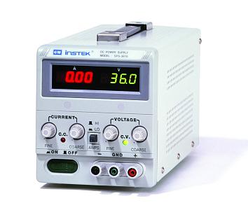
Регулируемый импульсный источник питания SPS-3610 предназначен для питания радиотехнических устройств стабилизированным постоянным напряжением и током. Источник питания может использоваться в лабораториях и на производстве.
В источнике SPS3610 установлен импульсный преобразователь, который обеспечивает выходное напряжение от 0 до 36 В, выходной ток от 0 до 10А, максимальную мощность 360 Вт. С помощью регуляторов осуществляется плавная установка выходных параметров. Встроенная защита от перегрузки, от не правильного подключения и от переполюсовки обеспечивает стабильную работу прибора на протяжении всего срока службы.
Нет в наличии
Дата ближайшей поставки: 18.08.2023 г. Возможность приобретения товара из данной поставки требует уточнения у менеджера Узнать о поступлении
Старая цена:
45 568 Р
Цена (с НДС):
34 800 Р
Стоимость поверки (с НДС):
2 820 Р
Торговая марка:
GW Instek
Напряжение, В:
36
Ток, А:
10
Срок гарантии (лет):
1
Госреестр СИ:
№20189-07 до 07.08.2027 г.
Страна производитель:
КИТАЙ
Поделиться:
Характеристики
Комплектация
Библиотека
Максимальное напряжение 1 канал
36 В
Максимальный ток 1 канал
10 А
Максимальная мощность
360 Вт
Тип преобразования
Импульсный
Особенности
Дополнительный выход (для тока нагрузки > 3 А).
Источник питания SPS-3610
1 шт.
Шнур питания
1 шт.
Тестовый провод GTL-203A
1 шт.
Инструкция по эксплуатации
1 шт.
Внимание! Отсутствие ошибок и опечаток не гарантируется. В технические характеристики средств измерений неутвержденного типа производителем могут быть внесены изменения без предварительного уведомления. Соответствие важных параметров требует уточнения. Полные технические характеристики предоставляются по отдельному запросу. Нашли ошибку? Выделите мышкой и нажмите Ctrl+Enter.
Регулируемый импульсный источник питания SPS-3610 предназначен для питания радиотехнических устройств стабилизированным постоянным напряжением и током. Источник питания может использоваться в лабораториях и на производстве.
В источнике SPS3610 установлен импульсный преобразователь, который обеспечивает выходное напряжение от 0 до 36 В, выходной ток от 0 до 10А, максимальную мощность 360 Вт. С помощью регуляторов осуществляется плавная установка выходных параметров. Встроенная защита от перегрузки, от не правильного подключения и от переполюсовки обеспечивает стабильную работу прибора на протяжении всего срока службы.
Задняя панель SPS-3610
На задней панеле источника питания SPS-3610 установлены несколько разъемов, которые обеспечивают следующие возможности:
Дистанционное управление прибором позволяет осуществлять включение и отключение выходного тока
Подключение удаленной нагрузки к разъемам на задней панеле исключает просадки напряжения на соединительных проводах.
Особенности источника питания SPS-3610
Дополнительный выход для тока более 3 А;
Низкий уровень внутреннего шума;
Высокий уровень КПД до 70%;
Регулировка выходных параметров по принципу грубо/точно;
Одновременное отображение тока и напряжения;
Небольшой вес и ручка для переноски.
Купить импульсный источник питания SPS-3610 получить консультацию специалистов, оформить заказ вы можете в магазине Союз-Прибор, позвонить по телефону или отправить письмо по электронной почте. Мы предоставляем только надёжное оборудование по самым выгодным ценам.
View a manual of the GW Instek SPS-3610 below. All manuals on ManualsCat.com can be viewed completely free of charge. By using the ‘Select a language’ button, you can choose the language of the manual you want to view.
MANUALSCAT | EN
Question & answers
Have a question about the GW Instek SPS-3610 but cannot find the answer in the user manual? Perhaps the users of ManualsCat.com can help you answer your question. By filling in the form below, your question will appear below the manual of the GW Instek SPS-3610. Please make sure that you describe your difficulty with the GW Instek SPS-3610 as precisely as you can. The more precies your question is, the higher the chances of quickly receiving an answer from another user. You will automatically be sent an e-mail to inform you when someone has reacted to your question.
Ask a question about the GW Instek SPS-3610
Page: 1
i
DC POWER SUPPLY
(Switching Mode)
SPS-1230/1820/3610/2415/606
USER MANUAL
GW INSTEK PART NO. 82PS-36100MI1
Page: 2
ii
ISO-9001 CERTIFIED MANUFACTURER
SAFETY TERMS AND SYMBOLS
These terms may appear in this manual or on the product:
WARNING. Warning statements identify condition or practices that could result in injury or loss of life.
CAUTION. Caution statements identify conditions or practice that could result in damage to this
product or other property.
WARNING: This equipment is not for measurements performed for CAT II, III and IV.
Measurement category I is for measurements performed on circuits not directly connected to MAINS.
Measurement category II is for measurements performed on circuits directly connected to the low voltage installation.
Measurement category III is for measurements performed in the building installation.
Measurement category IV is for measurements performed at the source of the low-voltage installation.
The following symbols may appear in this manual or on the product:
DANGER
High Voltage
DANGER
Hot Surface
ATTENTION
refer to Manual
Protective
Conductor
Earth(ground)
terminal
Page: 3
iv
FOR UNITED KINGDOM ONLY
NOTE
This lead/appliance must only
be wired by competent persons
WARNING
THIS APPLIANCE MUST BE
EARTHED
IMPORTANT
The wires in this lead are
coloured in accordance with
the following code:
Green/
Yellow: Earth
Blue : Neutral
Brown: Live
(Phase)
As the colours of the wires in main leads may not correspond with the colours marking
identified in your plug/appliance, proceed as follows:
The wire which is coloured Green & Yellow must be connected to the Earth terminal marke
with the letter E or by the earth symbol or coloured Green or Green & Yellow.
The wire which is coloured Blue must be connected to the terminal which is marked with th
Letter N or coloured Blue or Black.
The wire which is coloured Brown must be connected to the terminal marked with the letter
or P or coloured Brown or Red.
If in doubt, consult the instructions provided with the equipment or contact the supplier.
This cable/appliance should be protected by a suitably rated and approved HBC mains fuse;
refer to the rating information on the equipment and/or user instructions for details. As a
guide,
cable of 0.75mm ² should be protected by a 3A or 5A fuse. Larger conductors would norma
require 13A types, depending on the connection method used.
Any moulded mains connector that requires removal/replacement must be destroyed by rem
of any fuse & fuse carrier and disposed of immediately, as a plug with bared wires is hazard
if a engaged in live socket. Any re-wiring must be carried out in accordance with the inform
detailed on this label.
Page: 4
v
EC Declaration of Conformity
We
GOOD WILL INSTRUMENT CO.,LTD.
No. 7-1, Jhongsing Rd., Tucheng City, Taipei County 236, Taiwan
GOOD WILL INSTRUMENT (SUZHOU) CO., LTD.
No.69 Lushan Road, Suzhou New District Jiangsu, China.
declare, that the below mentioned products
SPS-1230, SPS-1820, SPS-3610, SPS-2415, SPS-606
are herewith confirmed to comply with the requirements set out in the Council Directive on the Approximation
of the Law of Member States relating to Electromagnetic Compatibility (89/336/EEC, 92/31/EEC, 93/68/EEC)
and Low Voltage Equipment Directive (73/23/EEC, 93/68/EEC).
For the evaluation regarding the Electromagnetic Compatibility and Low Voltage Equipment Directive, the
following standards were applied:
EN 61326-1: Electrical equipment for measurement, control and laboratory use —
EMC requirements (1997+A1: 1998+A2:2001)
Conducted Emission Electrostatic Discharge EN 61000-4-2:1995+A1:1998
Radiated Emission
EN 55011:1998 Class A
Radiated Immunity EN 61000-4-3:1996+A1:1998
Electrical Fast Transients EN 61000-4-4:1995
Current Harmonic EN61000-3-2: 2000
Surge Immunity EN 61000-4-5:1995
Voltage Fluctuation EN61000-3-3:1995 Conducted Susceptibility EN 61000-4-6:1996
—————— ————————- Power Frequency Magnetic field EN 61000-4-8:1993
—————— ————————- Voltage Dip/Interruption EN 61000-4-11:1994
Low Voltage Equipment Directive 73/23/EEC & amended by 93/68/EEC
Low Voltage Directive IEC/ EN 61010-1: 2001
Page: 5
vi
CONTENTS
1. INTRODUCTION…………………………………………………………………………………………………………………………………………………1
2. SPECIFICATION …………………………………………………………………………………………………………………………………………………2
2-1. GENERAL …………………………………………………………………………………………………………………………………………………………2
2-3. CONSTANT CURRENT OPERATION………………………………………………………………………………………………………………………..3
2-4. INDICATOR METER…………………………………………………………………………………………………………………………………………….3
2-5. OVER VOLTAGE PROTECTION ……………………………………………………………………………………………………………………………..3
2-6. INSULATION ……………………………………………………………………………………………………………………………………………………..3
3. PRECAUTIONS BEFORE OPERATION ……………………………………………………………………………………………………………..4
3.1 UNPACKING THE SWITCHING POWER SUPPLY …………………………………………………………………………………………………………4
3.2 CHECKING THE LINE VOLTAGE …………………………………………………………………………………………………………………………….4
3.3 ENVIRONMENT …………………………………………………………………………………………………………………………………………………..5
3.4 EQUIPMENT INSTALLATION, AND OPERATION…………………………………………………………………………………………………………5
4. THEORY OF OPERATION (SEE FIGURE 4-1)……………………………………………………………………………………………………6
5. PANEL CONTROLS AND INDICATORS…………………………………………………………………………………………………………….8
5-1. FRONT PANEL……………………………………………………………………………………………………………………………………………………9
5-2. REAR PANEL……………………………………………………………………………………………………………………………………………………..9
6. OPERATION INSTRUCTIONS ………………………………………………………………………………………………………………………….12
6-1. PRECAUTION …………………………………………………………………………………………………………………………………………………..12
6-2. SETTING CURRENT LIMIT………………………………………………………………………………………………………………………………….15
6-3. CONSTANT VOLTAGE / CONSTANT CURRENT CROSSOVER CHARACTERISTIC ……………………………………………………………15
6-4. OPERATION MODE: VOLTAGE OPERATION MODE …………………………………………………………………………………………………15
6-5. REMOTE ERROR SENSING …………………………………………………………………………………………………………………………………16
6-6. REMOTE CONTROL…………………………………………………………………………………………………………………………………………..18
6-7. OVP SETTING …………………………………………………………………………………………………………………………………………………18
7. MAINTENANCE ………………………………………………………………………………………………………………………………………………..19
7-1. FUSE REPLACEMENT………………………………………………………………………………………………………………………………………..19
7-2. LINE VOLTAGE CONVERSION …………………………………………………………………………………………………………………………….19
7-3. INTERNAL ADJUSTMENTS ………………………………………………………………………………………………………………………………….20
7-4 CLEANING……………………………………………………………………………………………………………………………………………………….22
Page: 6
1
1. INTRODUCTION
The series of switching power supplies for measuring instrument have ruled out the inconvenience of big
volume and heavyweight of a traditional power supply possess.
The output voltage and current is controlled by two variable resistors with coarse and fine regulation for more
handy and precise adjustment.
Features:
z With more extensive range of input voltage at 97V~133V (for 115V) and 195V~265V (for 230V).
z With high frequency operation can reduce the size of power transformer.
z With small size, light weight and high density power.
z Entire efficiency rate higher up to 70%.
z Auto control the voltage and current mode.
z Zero adjustment for the output of voltage and current.
Page: 7
2
2. SPECIFICATION
2-1. General
Main supply : 115V/230V±15% 50/60Hz (Switch selectable).
Rating, dimension and weight : See Table 2-1.
Table 2-1
MAX. RATING INPUT RATING FUSE STYLE & RATING WEIGHT
Model
Voltage Current Watts VA 115V 230V kg
SPS-1230 12V 30A
SPS-1820 18V 20A
SPS-2415 24V 15A
SPS-3610 36V 10A
SPS-606 60V 6A
500 900 T 10A 250V T 6.3A 250V 3.3
Dimensions:128(W) × 145(H) × 285(D) mm.
WARNING: Voltage over 60V DC is a lethal shock hazard to the user. Be careful when
connecting power supplies in series to achieve voltage higher than 60V DC totally or 60V
DC between any connection and earth ground.
Operation Environment : Indoor use,
Altitude up to 2000m,
Installation Category II,
Pollution degree 2.
Operation Temperature &Humidity : 0℃ to 40℃, <80%.
Storage Temperature & Humidity : -10℃ to 70℃, <70%.
Accessories : Test Lead (current < 4A)…………………………………………… × 1
Operation Manual..…………………………………………………………. × 1
Page: 8
3
2-2. Constant Voltage Operation
(1) Output Voltage ranges from 0 to rating voltage with continuous adjustment.
(2) Voltage regulation
line regulation≦5mV.
load regulation≦5mV.
(3) Recovery time≦500μs(50% Load change, minimum load 0.5A).
(4) Ripple & Noise≦5mVrms, 100mVp-p (tested by 20MHz oscilloscope.)
(5) Temperature coefficient≦100ppm/℃.
2-3. Constant Current Operation
(1) Output current ranges from 0 to rating current with continuous adjustment.
(2) Current regulation
line regulation≦3mA.
load regulation≦3mA.
SPS-606 SPS-3610 SPS-2415 SPS-1820 SPS-1230
(3) Ripple & Noise
≦3mArms ≦5mArms ≦10mArms ≦10mArms ≦30mArms
2-4. Indicator Meter
1)Voltage:
Display : 3 1/2 Digits 0.39” Green LED display.
Accuracy : ±(0.5% of rdg + 2 digits).
2)Current:
Display : 3 1/2 Digits 0.39” Red LED display.
Accuracy : ±(0.5% of rdg + 2 digits).
2-5. Over Voltage Protection
(1) Over Voltage Protection ranges from 5% rating to rating +5.5%.
(2) OVP Accuracy ±(Vset 1%+0.6V)
2-6. Insulation
Between Chassis and Output Terminal : ≧20MΩ (DC500V).
Between Chassis and AC Cord : ≧30MΩ (DC500V).
Page: 9
4
3. PRECAUTIONS BEFORE OPERATION
3.1 Unpacking the Switching Power Supply
The instrument has been fully inspected and tested before shipping from the factory. Upon receiving the
instrument, please unpack and inspect it to check if there is any damages caused during transportation. If any sign
of damage is found, notify the bearer and/or the dealer immediately.
3.2 Checking the Line Voltage
The instrument can be used with line voltages shown in the table below. Before connecting the power plug to an
AC line outlet, make sure the voltage selector of the rear panel is set to the correct position and the proper fuse
installed corresponding to the line voltage. The unit may be damaged if connected to the wrong AC line voltage.
WARNING: To avoid electrical shock the power cord protective grounding conductor must be
connected to ground.
When line voltages are changed, replace the required fuses shown below.
Line voltage Range Fuse Line voltage Range Fuse
115V 97-133V T 10A 250V 230V 195-250V T 6.3A 250V
WARNING: To avoid personal injury, disconnect the power cord before removing the fuse
holder.
Page: 10
5
3.3 Environment
The normal ambient temperature range of this instrument is from 0° to 40°C (32° to 104°F). Operation of the
instrument above this temperature range may cause damage to the circuits.
Do not use the instrument in a place where strong magnetic or electric field exists as it may disturb the
measurement.
3.4 Equipment Installation, and Operation
Ensure there is proper ventilation for the vents in the SPS power supplies case. If this equipment is used in a
manner not according to the specification, the protection provided by the equipment may be impaired.
WARNING: This is a Class A product. In a domestic environment this product may cause
radio interference in which case the user may be required to take adequate measures.
WARNING: This equipment is not for measurements performed for CAT II, III and IV.
Page: 11
6
4. THEORY OF OPERATION (See Figure 4-1)
z Block Configuration of SPS- System
The SPS-Series comprise a Bridge rectifier, a Pulse Width Modulation, a Driver Circuit, a Driver Transformer,
a Rectifier Circuit, a Voltage Control Circuit, a Current Shunt, an Output Filter, a Voltage/Current Adjusting
Circuit, a Buffer Circuit, an Error Amplifier, an Opto-Isolator, and an Auxiliary Switching Supply and etc.
z Component List for each circuit configuration
Bridge Rectifier: BD101.
Pulse Width Modulation: U102.
Driver Circuit: T104, Q105~Q108.
Driver Transformer: T301.
Rectifier Circuit: D301,D3011.
Voltage Control Circuit: Q303.
Current Shunt: R341.
Output Filter: Common Choke L302, C325.
Voltage/Current Adjusting Circuit: U302.
Buffer Circuit: U302, Q301.
Error Amplifier: U301, U303.
Opto-isolator: U304.
Auxiliary Switching Supply: U201, U202, T201.
OVP: U401, U402
Remote Control: RL401, D402
Page: 12
7
z Description of Circuit Theory
1) +10V Voltage reference circuit:
Start up the circuits of R306 and D302 to ensure the output voltage of OPA U301, PIN 1 is in positive status when power
is on. At this moment, the output voltage of PIN 1 will pass through R307 to maintain the voltage of both ends of
ZENER DIODE ZD301(6.2V) to 6.2V. As OPA has the character of false short circuit, so U301 PIN3=6.2V, refer to the
following formula:
Therefore, the OPA’s output voltage can be changed by adjusting the VR301 as shown in the following formula:
Vref=10V→VR301=1.14kΩ
2) Voltage Adjusting Circuit
The R311, and R313 are voltage feedback attenuating resistors while R312 is to control the output of Reference voltage.
Please refer to the following formula:
If Vref=10V R311=52.3kΩ R313=20kΩ
And the R316, R317, C313, C314, and C315 are compensated circuits for voltage frequency.
3) Current Adjusting Circuit:
The U302 is an Error Amplifier with the gain at:
For example: SPS-1820, Io=20A,R341=10mΩ
Vpin12=Io×R341×A=20×0.01×28.01=5.602V
Page: 13
9
5-1. Front panel
(1) CV Indicator Lights when the power is on and in constant voltage operation.
(2) CC Indicator Lights when in constant current operation.
(3) Voltage coarse For the coarse adjustment of the output voltage.
(4) Voltage fine For the fine adjustment of the output voltage.
(5) Current coarse For the coarse adjustment of the output current.
(6) Current fine For the fine adjustment of the output current.
(7) “+” output terminal Positive polarity (Red) (MAX. 3A output only).
(8) “GND” terminal Earth and chassis ground (Green).
(9) “–“output terminal Negative polarity (Black) (MAX. 3A output only).
(10) Meter Indicates the output voltage.
(11) Meter Indicates the output current.
(12) Power control On/Off switch.
(13) Current HI/LO control Current indicates HI/LO range selection.
HI range: Output current range is from 0 to rating current.
LO range: Output current range is from 0 to half-rating current.
5-2. Rear panel
(14) Fuse holder
(15) Power socket.
(16) AC selects switch With 115V or 230V voltage and current ranges selection (Refer to the
diagrammatic instruction to prevent mis-operating).
(17) Fan Cooling fan.
(18)
(19)
(20)
(21)
(22)
(23)
(24)
(25)
(26)
S+ sense terminal
S– sense terminal
+ output terminal
– output terminal
Ground terminal
Remote Control
OVP ADJ
M+ sense terminal
nM- sense terminal
A positive input voltage remote sense terminal.
A negative input voltage remote sense terminal.
Screw type + output terminal.
Screw type – output terminal.
Screw type ground terminal (connected to case chassis).
Short or open the remote control terminal for output on or off.
Adjust trimmer VR401 to set the OVP value.
A positive output voltage monitor terminal.
A negative output voltage monitor terminal.
Remark: As the front panel has 3A current limit and no remote sense terminal, it is recommended to use rear
output terminal for most of the applications.
Page: 14
12
6. OPERATION INSTRUCTIONS
6-1. Precaution
(1) AC input
AC input should be within the range of line voltage±15% 50/60Hz.
WARNING: To avoid electrical shock, the power cord protective grounding conductor must be
connected to ground.
(2) Installation
The machine itself is a heating source , please don’t pile up the machine while operation. Keep the machine
from other heating source at least for 10cm to assure a sufficient space for radiation in order to extend the life of
the machine. The heat sink located at rear of the power supply must have sufficient space for radiation.
CAUTION: To prevent the instrument from damage, ensure the working environment is under
40℃ of temperature. If exceeding 40℃, please refer to the drawing shown as (3) of next page.
Page: 15
14
(4) Output Test lead Selection:
The Selection of Output Test Lead and Feedback Test Lead:
For safety assurance, please select the adequate output test lead according to the following list:
Conductor
UL
(CSA)
Model
Wire No.
AWG
Component
pc/mm
Cross Section Area
(mm)
2
Outer
Diameter
mm
Maximum
Conductive
Resistor
Ω/km
Permissible
Current
A(amp)
24 11/0.16 0.22 0.64 88.6 7.64
22 17/0.16 0.34 0.78 62.5 10.0
20 21/0.18 0.53 0.95 39.5 13.1
18 34/0.18 0.87 1.21 24.4 17.2
16 26/0.254 1.32 1.53 15.6 22.6
14 41/0.254 2.08 2.03 9.90 30.4
12 65/0.254 3.29 2.35 6.24 40.6
1015
TEW
(Twisted Wire)
10 65/0.32 5.23 3.00 3.90 55.3
Remark:
1. The ambient temperature of “Permissible Current” is at 40℃, the withstanding temperature of conductor is at 105
℃ according to the condition of the distributed single wire.
2. The permissible current listed as above is suggested to be used under 70%.
3. If the feedback test leads are in need, the level above UL(CSA) AWG24, 22, 20… can be accepted. Besides,
when the load is a capacitive load, please use the twine wire by twisting (+)output test lead with (S+) feedback
test lead. Same way used on (-) output test lead and (S-) feedback test lead.
4. When the current value exceeds above suggestive list, can select more wires used in parallel according to above
list.
Page: 16
15
6-2. Setting Current Limit
(1) Determine the maximum safe current for the device to be powered.
(2) Temporarily short the (+) and (-) terminals of the power supply together with a test lead.
(3) Rotate the COARSE VOLTAGE control away from zero sufficiently to have the CC indicator lightened.
(4) Adjust the CURRENT control for the desired current limit. Read the current value on the Ammeter.
(5) The current limit (overload protection) has now been preset. Do not change the CURRENT control setting after this
step.
(6) Remove the short between the (+) and (-) terminals and hook up for constant voltage operation.
6-3. Constant Voltage / Constant Current Crossover Characteristic
The working characteristic of this series is called a constant voltage/constant current automatic crossover type. This
permits continuous transition from constant current to constant voltage modes in response to the load change. The
intersection of constant voltage and constant current modes is called the crossover point. Fig.6-1 shows the
relationship between this crossover point and the load.
For example, if the load is such that the power supply is operating in the constant voltage mode, a regulated output
voltage is provided. The output voltage remains constant as the load increases, up until the point where the preset
current limit is reached. At that point, the output current becomes constant and the output voltage drop is
proportioned to further increases in load. The crossover point is indicated by the front panel LED indicators. The
crossover point is reached when the CV indicator goes out and the CC indicator is on.
Fig. 6-1 Constant Voltage/Constant Current Characteristic.
Similarly, crossover from the constant current to the constant voltage mode automatically occurs from a decrease in
load, a good example of this would be seen when charging a 12 volt battery. Initially, the open circuit voltage of
the power supply may be preset for 13.8 volts. A low battery will place a heavy load on the supply and it will
operate in the constant current mode, which may be adjusted for a 1 amp charging rate. As the battery becomes
charged, and its voltage approaches 13.8 volts, its load decreases to the point where it no longer demands the full 1
amp charging rate. This is the crossover point where the power supply goes into the constant voltage mode.
6-4. Operation mode: Voltage Operation Mode
A. Set Power switch to “OFF” position.
B. Make sure that line voltage is correct for the input power voltage.
Page: 17
16
C. Plug power cord into the power outlet.
D. Set Power switch to “ON” position.
E. Adjust “Voltage” and “Current” control to the desired output voltage and current.
F. Connect the external load to the output binding posts. Make sure both “+” and “-” terminals are connected
correctly.
6-5. Remote Error Sensing
A normal power supply can perform its best load regulation, line regulation, low output impedance, and low output
ripple and noise, as well as the rapidly transient recovery response. Please refer to figure 6-2. If there is any test lead
connected between load and output terminal, the best characters of power supply can not be shown up on the load
terminal.
Figure 6-2 The power supply with local error sensing
Page: 18
17
The function of the Remote Error Sensing can only be applied to the Constant Voltage mode as shown in Figure 6-3. The
feedback point of power supply must start from the load terminal directly. Therefore, the power supply can display its
function on the load terminal instead of output terminal. To compensate the voltage drop causing from the test lead, it
needs to shift the voltage from the output terminal of power supply, and the voltage on the load terminal remains
unchanged. A large test lead is recommended in order to reduce the voltage drop as less as better on the test lead (typical
0.5V maximum).
Never use the Sense connections without connecting the normal large test lead to output terminal.
Figure 6-3 The power supply with remote error sensing
Error Sensing Open Protection
The sensing circuit must avoid open circuit without equipping with Relay, Switch, and Connector. When the open circuit
is occurred abruptly on the sensing circuit, it will cause overshoot on the output terminal. To prevent this kind of
phenomenon, add small resistance R1 and R2 or replace with diode as shown in the Figure 6-4.
Figure 6-4 The power supply with remote error sensing protection
Page: 19
18
6-6. Remote Control
Short the Remote Control terminal for output ON, and open the Remote Control terminal for output OFF.
6-7. OVP Setting
Firstly, adjust the OVP ADJ knob clockwise to the maximum OVP, then adjust output voltage to reach the voltage of OVP.
Secondly, adjust the OVP ADJ knob counter-clockwise slowly until the OVP message appears. Then the setting value of
OVP is slightly less than the OVP which you intend to set.
Page: 20
19
7. MAINTENANCE
The following instructions are used by qualified personnel only. To avoid electrical shock, do not perform any
servicing other than the operating instructions of the manual unless you are qualified to do so.
7-1. Fuse Replacement
If the fuse blown, the CV or CC indicators will not light and the power supply will not operate. The fuse should
not normally blow unless a problem has developed in the unit. Try to determine and correct cause of the blown
fuse, then replace only with a fuse of the correct rating and type.
The fuse is located on the rear panel (see Fig. 5-2).
WARNING: For continued fire protection. Replace with 250V fuse of the specified type and
rating, and disconnect the power cord before replacing fuse.
7-2. Line Voltage conversion
The primary winding of the power transformer is tapped to permit operation from 115/230 VAC, 50/60 Hz line
voltage. Conversion from one line voltage to another is done by change AC selects switch as shown in Fig. 5-2.
To convert to different line voltage, perform the following procedure:
(1) Make sure the power cord is unplugged.
(2) Set the AC switch to the desired line voltage position.
(3) The change of line voltage may also require a corresponding change of fuse value. Install correct fuse value
according to the instruction shown on rear panel.
Page: 21
20
7-3. Internal adjustments
The unit was accurately adjusted at the factory before shipment. So, readjustment is suggested only when the
accuracy of circuit is affected by the repair, or when you have the reason to believe that the unit is out of accuracy.
The recommended calibration device is a multi-meter with an accuracy of ±0.1% dcv or better. (GOOD WILL
model GDM-8145 or equivalent).
If readjustment is required, proceed the following procedure. Locations of the adjustments are shown in Fig. 6-1
and Fig.7-2.
(1) Adjustment of the Rating Voltage
A. Connect an accurate (±0.1%) external multi-meter to measure the dc voltage at output terminals of the power
supply.
B. Set the COARSE and FINE VOLTAGE controls to maximum (fully clockwise).
C. Adjust trimmer VR301 for a reading on the multi-meter to be 18.50V for SPS-1820, 36.50V for SPS-3610,
and 60.50V for SPS-606, 24.5V for SPS-2415, 12.5V for SPS-1230.
D. Adjust trimmer pot VR2 to set the reading value of voltmeter as same as the one shown on the multi-meter..
(2) Adjustment of the rating Current
A. Set the CURRENT control to HI.
B. Set the COARSE and FINE CURRENT controls to minimum (fully counterclockwise).
C. Set the COARSE and FINE VOLTAGE controls to the center position.
D. Connect an external multi-meter to measure dc current of output terminal.
E. Adjust trimmer VR304 to have a reading of –0.00A indicated on the current meter.
F. Set the COARSE and FINE CURRENT controls to maximum (fully clockwise)
G. Adjust trimmer VR303 for a reading on the multi-meter to be 20.10A for SPS-1820, 10.10A for SPS-3610,
and 6.10A for SPS-606, 15.1A for SPS-2415, 30.1A for SPS-1230.
H. Adjust trimmer VR2 to set the reading value of Amp-meter as the same as the one shown on the multi-meter.
I. Set CURRENT control to LOW.
J. Adjust trimmer VR310 to set the reading value of Amp-meter as 0.5 times to the rating current.
K. Adjust trimmer VR401 to set the OVP value (see Fig. 7-3).
22
7-4 Cleaning
To clean the power supply, use a soft cloth dampened in a solution of mild detergent and water. Do not spray
cleaner directly onto the instrument, since it may leak into the cabinet and cause damage. Do not use chemicals
containing benzene, benzene, toluene, xylem, acetone, or similar solvents. Do not use abrasive cleaners on any
portion of the instrument.
Дата ближайшей поставки: 15.09.2023 г. Возможность приобретения товара из данной поставки требует уточнения у менеджера Узнать о поступлении
Старая цена:
39 060 Р
Цена (с НДС):
34 800 Р
Стоимость поверки (с НДС):
2 820 Р
Торговая марка:
GW Instek
Напряжение, В:
36
Ток, А:
10
Срок гарантии (лет):
1
Госреестр СИ:
№20189-07 до 07.08.2027 г.
Страна производитель:
КИТАЙ
Поделиться:
Характеристики
Комплектация
Библиотека
Максимальное напряжение 1 канал
36 В
Максимальный ток 1 канал
10 А
Максимальная мощность
360 Вт
Тип преобразования
Импульсный
Особенности
Дополнительный выход (для тока нагрузки > 3 А).
Источник питания SPS-3610
1 шт.
Шнур питания
1 шт.
Тестовый провод GTL-203A
1 шт.
Инструкция по эксплуатации
1 шт.
Внимание! Отсутствие ошибок и опечаток не гарантируется. В технические характеристики средств измерений неутвержденного типа производителем могут быть внесены изменения без предварительного уведомления. Соответствие важных параметров требует уточнения. Полные технические характеристики предоставляются по отдельному запросу. Нашли ошибку? Выделите мышкой и нажмите Ctrl+Enter.