- Manuals
- Brands
- Fluke Manuals
- Measuring Instruments
- DTX Series
- User manual
-
Contents
-
Table of Contents
-
Bookmarks
Quick Links
DTX Series
CableAnalyzer
™
Users Manual
PN 2142201
April 2004 Rev. 6 6/09
©2004, 2006-2009 Fluke Corporation. All rights reserved. Printed in USA.
All product names are trademarks of their respective companies.
Related Manuals for Fluke DTX Series
Summary of Contents for Fluke DTX Series
-
Page 1
DTX Series CableAnalyzer ™ Users Manual PN 2142201 April 2004 Rev. 6 6/09 ©2004, 2006-2009 Fluke Corporation. All rights reserved. Printed in USA. All product names are trademarks of their respective companies. -
Page 2
90 days, unless otherwise stated. Ni-Cad, Ni-MH and Li-Ion batteries, cables or other peripherals are all considered parts or accessories. The warranty extends only to the original buyer or end user customer of a Fluke Networks authorized reseller, and does not apply to any product which, in Fluke Networks’… -
Page 3: Table Of Contents
Table of Contents Title Page Overview of Features ………………..1 Registration ……………………2 Contacting Fluke Networks ………………2 Accessing the Technical Reference Handbook …………3 Additional Resources for Cable Testing Information ……….3 Unpacking ……………………4 DTX-1800 ……………………. 4 DTX-1200 ……………………. 4 DTX-LT ……………………
-
Page 4
DTX Series CableAnalyzer Users Manual Setting the Reference for Twisted Pair Cabling ………… 20 Twisted Pair Test Settings ………………22 Autotest on Twisted Pair Cabling …………….25 Autotest Summary Results for Twisted Pair Cabling ……….29 PASS*/FAIL* Results ………………..30 Automatic Diagnostics ……………….. -
Page 5
Table of Contents Uploading Results to a PC ………………56 Options and Accessories ………………..57 About LinkWare and LinkWare Stats Software …………62 Maintenance ……………………. 63 Cleaning ……………………63 Factory Calibration ………………..63 Updating the Tester’s Software …………….64 Updating with a PC ………………… 64 Updating with Another Tester ……………. -
Page 6
DTX Series CableAnalyzer Users Manual… -
Page 7: List Of Figures
List of Figures Figure Title Page Tester Front Panel Features ………………..8 Tester Side and Top Panel Features ………………10 Smart Remote Features………………….12 Removing the Battery Pack………………..15 Smart Remote Battery Status Shown After Power-Up…………15 Attaching and Removing Adapters………………16 Handling Guidelines for Permanent Link Adapters …………
-
Page 8
DTX Series CableAnalyzer Users Manual Coaxial Network Cabling Test Connections ……………. 38 Coaxial Video Cabling Test Connections…………….39 Autotest Results for Coaxial Cabling………………. 40 Network Module Features ………………..42 Installing and Removing the Network and SFP Modules……….. 43 Network Test Connections ………………..46 Network Connectivity Results Screen (DHCP example for twisted pair) …… -
Page 9: Overview Of Features
• Overview of Features Automatic diagnostics report distance to and likely causes of common faults. The DTX Series CableAnalyzers are rugged, hand-held • Toner feature helps you locate jacks and automatically instruments used to certify, troubleshoot, and document starts an Autotest upon tone detection.
-
Page 10: Registration
Autotest results, including graphical data, on a 128 MB removable memory card. (See page 54 for Note storage recommendations.) If you contact Fluke Networks about your tester, • have the tester’s software and hardware version Runs for at least 12 hours on the rechargeable lithium numbers available if possible.
-
Page 11: Accessing The Technical Reference Handbook
Additional Resources for Cable Testing Japan: 03-3434-0510 • Information Korea: 82 2 539-6311 • Singapore: 65-6799-5566 The Fluke Networks Knowledge Base answers common • questions about Fluke Networks products and provides Taiwan: (886) 2-227-83199 articles on cable testing techniques and technology. • USA: 1-800-283-5853 To access the Knowledge Base, log on to Visit our website for a complete list of phone numbers.
-
Page 12: Unpacking
Users Manual Unpacking DTX-1200 • DTX-1200 CableAnalyzer with lithium-ion battery The DTX Series CableAnalyzers come with the accessories pack listed below. If something is damaged or missing, contact • DTX-1200 SmartRemote with lithium-ion battery pack the place of purchase immediately.
-
Page 13: Dtx-Lt
Warning or Caution: Risk of damage or • Two ac adapters destruction to equipment or software. See • DTX Series CableAnalyzer Users Manual explanations in the manuals. • DTX Series CableAnalyzer Product CD Do not connect this equipment to public •…
-
Page 14
Do not modify the tester. To avoid disrupting network operation, to • Use only ac adapters approved by Fluke Networks avoid damaging the tester or cables under test, for use with the DTX tester to charge the battery to avoid data loss, and to ensure maximum or power the tester. -
Page 15
See pages 16 and 17 the DTX-MFM2/GFM2/SFM2 Fiber Module Users for important handling information. Manual or the DTX Series CableAnalyzer Technical Reference Handbook. • Leave the module bay covers in place when modules are not installed. -
Page 16: Getting Acquainted
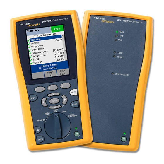
DTX Series CableAnalyzer Users Manual Getting Acquainted Physical Features Figures 1 and 2 describe the tester’s features. Figure 3 The following sections introduce the tester’s basic features. describes the smart remote’s features. EXIT TEST ENTER SAVE AUTO TEST SINGLE SETUP…
-
Page 17
Getting Acquainted LCD display with backlight and adjustable brightness. : Press to switch the backlight between bright and dim settings. Hold for 1 second to adjust the display : Starts the currently selected test. Activates the tone contrast. generator for twisted pair cabling if no smart remote is B C A D detected. -
Page 18
DTX Series CableAnalyzer Users Manual amd33f.eps Figure 2. Tester Side and Top Panel Features… -
Page 19
) and RS-232C ( : DTX-1800, DTX-1200) ports for uploading test reports to a PC and updating the tester’s software. The RS-232C port uses a custom DTX cable available from Fluke Networks. Figure 2. Tester Side and Top Panel Features (cont.) -
Page 20
DTX Series CableAnalyzer Users Manual amd30f.eps Figure 3. Smart Remote Features… -
Page 21
Getting Acquainted Caution Low battery LED lights when the battery is low. : Starts the test currently selected on the main unit. All the LEDs flash if the smart remote detects Activates the tone generator for twisted pair cabling if excessive voltage on the cable. -
Page 22: Powering The Tester
DTX Series CableAnalyzer Users Manual • Powering the Tester If the battery does not reach full charge within 6 hours, the battery LED flashes red. Verify that the • You may charge the battery when it is attached or battery was within the temperature range given detached from the tester.
-
Page 23
Getting Acquainted PASS TEST 84 % — 100 % FAIL PASS TALK 67 % — 83 % TONE TEST 51 % — 66 % LOW BATTERY FAIL 34 % — 50 % TALK TEST 18 % — 33 % TALK TONE 0 % — 17 % LOW BA… -
Page 24: About Link Interface Adapters
DTX Series CableAnalyzer Users Manual About Link Interface Adapters Link interface adapters provide the correct jacks and interface circuitry for testing different types of twisted pair LAN cabling. The channel and permanent link interface adapters provided are suitable for testing cabling up to Cat 6.
-
Page 25
Getting Acquainted amd36f.eps Figure 7. Handling Guidelines for Permanent Link Adapters… -
Page 26
The optional DTX-PLCAL automated calibration kit lets you the module or the end of the cable. calibrate your permanent link adapters to compensate for physical changes that occur over time to the adapter’s cable and other components. Contact Fluke Networks for more information. -
Page 27: Preparing To Save Tests
Preparing to Save Tests Preparing to Save Tests Check the memory space available: Set the plot data storage option: Insert a memory card (DTX-1800 and 1200), turn the On the Instrument Settings menu select Store Plot rotary switch to SPECIAL FUNCTIONS; then select Data.
-
Page 28: Certifying Twisted Pair Cabling
DTX Series CableAnalyzer Users Manual Certifying Twisted Pair Cabling You do not need to set the reference after changing link interface adapters. Note Setting the Reference for Twisted Pair Cabling Turn on the tester and smart remote and let them The reference procedure sets a baseline for insertion loss, sit for 1 minute before setting the reference.
-
Page 29
Certifying Twisted Pair Cabling To set the reference, do the following: Attach permanent link and channel adapters and make the connections shown in Figure 9. Turn the rotary switch to SPECIAL FUNCTIONS and turn on the smart remote. Permanent link adapter Highlight Set Reference;… -
Page 30: Twisted Pair Test Settings
DTX Series CableAnalyzer Users Manual Twisted Pair Test Settings To access the settings, turn the rotary switch to SETUP, use to highlight Twisted Pair; then press Table 2 describes the settings that apply to twisted pair cabling tests. Table 2. Twisted Pair Test Settings…
-
Page 31
Certifying Twisted Pair Cabling Table 2. Twisted Pair Test Settings (cont.) Setting Description The Outlet Configuration setting determines which cable pairs are tested and which pair numbers SETUP > Twisted are assigned to the pairs. To see the wire map for a configuration, press Sample from the Pair >… -
Page 32
DTX Series CableAnalyzer Users Manual Table 2. Twisted Pair Test Settings (cont.) Setting Description SETUP > Twisted Pair > PASS*/FAIL Only: The tester shows HDTDX and HDTDR results only for Autotests with PASS*, HDTDX/HDTDR FAIL*, or FAIL results. All AUTOTESTs: The tester shows HDTDX and HDTDR for all Autotests. -
Page 33: Autotest On Twisted Pair Cabling
Certifying Twisted Pair Cabling Autotest on Twisted Pair Cabling Figure 10 shows the equipment needed for certifying twisted pair cabling. PASS TEST FAIL TALK TONE LOW BATTERY EXIT TEST ENTER SAVE AUTO TEST SINGLE SETUP TEST SPECIAL MONITOR FUNCTIONS TEST TALK TALK amd40f.eps…
-
Page 34
DTX Series CableAnalyzer Users Manual Autotest on Twisted Pair Cabling Attach adapters appropriate for the job to the tester Press on the tester or smart remote. To stop the test and the smart remote. at any time, press Turn the rotary switch to SETUP, then select Twisted… -
Page 35
Certifying Twisted Pair Cabling Horizontal cabling Optional consolidation point Work area Patch panel Wall outlet Start permanent permanent link link PASS TEST FAIL TALK TONE Tester with permanent Smart remote with LOW BATTERY link adapter permanent link adapter EXIT TEST ENTER SAVE AUTO… -
Page 36
DTX Series CableAnalyzer Users Manual Horizontal cabling Hub or switch Optional consolidation point Patch cord from hub or Work area switch Patch Wall panels outlet Start Patch channel cord channel from PC PASS TEST FAIL TALK TONE LOW BATTERY Tester with… -
Page 37: Autotest Summary Results For Twisted Pair Cabling
Certifying Twisted Pair Cabling Autotest Summary Results for Twisted Pair Cabling Figure 13 describes the Autotest Summary screen. PASS: All parameters are within limits. FAIL: One or more parameters exceed the limit. PASS*/FAIL*: One or more parameters are within the tester’s accuracy uncertainty range, and the “*”…
-
Page 38: Pass*/Fail* Results
DTX Series CableAnalyzer Users Manual PASS*/FAIL* Results A PASS* may be considered a passing result. A FAIL* should be considered a failure. A result marked with an asterisk means that measurements are in the tester’s accuracy uncertainty range (Figure 14) and the “*” notation is required by the selected test standard.
-
Page 39: Automatic Diagnostics
Automatic Diagnostics Automatic Diagnostics can take to solve the problem. A failed test may produce more than one diagnostic screen. In this case, press ADBC If an Autotest fails, press Fault Info for diagnostic to see additional screens. information about the failure. The diagnostic screens show Figure 15 shows examples of diagnostic screens.
-
Page 40: Certifying Coaxial Cabling
DTX Series CableAnalyzer Users Manual Certifying Coaxial Cabling You do not need to set the reference after changing link interface adapters. Certifying coaxial cabling requires the optional Note DTX-COAX coaxial adapters. Turn on the tester and let it sit for 1 minute before setting the reference.
-
Page 41
Certifying Coaxial Cabling To set the reference, do the following: Attach coaxial adapters to the main and remote testers, screw in the F-connector to BNC adapters; then make the connections shown in Figure 16. Turn the rotary switch to SPECIAL FUNCTIONS and turn on the smart remote. -
Page 42: Coaxial Test Settings
DTX Series CableAnalyzer Users Manual Coaxial Test Settings To access the settings, turn the rotary switch to SETUP, use to highlight Coaxial; then press Table 3 describes the settings that apply to coaxial cabling tests. Table 3. Coaxial Cable Test Settings…
-
Page 43
Certifying Coaxial Cabling Table 3. Coaxial Cable Test Settings (cont.) Setting Description SETUP > Instrument Standard: The tester displays and saves plot data for insertion loss. The tester saves data for Settings > Store Plot the frequency range required by the selected test limit. Data Extended: The tester saves data beyond the frequency range required by the selected test limit. -
Page 44: Autotest On Coaxial Cabling
DTX Series CableAnalyzer Users Manual Autotest on Coaxial Cabling Figure 17 shows the equipment needed for certifying coaxial cabling. PASS TEST FAIL TALK TONE LOW BATTERY EXIT TEST ENTER SAVE AUTO SINGLE TEST TEST SETUP SPECIAL MONITOR FUNCTIONS TEST TALK TALK amd138.eps…
-
Page 45
Certifying Coaxial Cabling Autotest on Coaxial Cabling Attach coaxial adapters to the tester and smart remote. If a fiber module is installed, you may need to press Change Media to select Coax as the media type. Turn the rotary switch to SETUP, then select Coaxial. Set the following on the Coaxial tab: Press on the tester or smart remote. -
Page 46
DTX Series CableAnalyzer Users Manual PASS TEST FAIL TALK TONE LOW BATTERY EXIT TEST ENTER SAVE AUTO TEST SINGLE SETUP TEST SPECIAL MONITOR FUNCTIONS TEST TALK TALK amd139.eps Figure 18. Coaxial Network Cabling Test Connections… -
Page 47
Certifying Coaxial Cabling Connection to coaxial cabling Wall outlet Female to female Female to female F-connector adapter F-connector adapter PASS TEST FAIL TALK TONE LOW BATTERY Tester with coaxial Smart remote with EXIT TEST adapter coaxial adapter ENTER SAVE AUTO TEST SINGLE TEST… -
Page 48: Autotest Results For Coaxial Cabling
DTX Series CableAnalyzer Users Manual Autotest Results for Coaxial Cabling Figure 20 describes the Autotest Summary screen. PASS: All parameters are within limits. FAIL: One or more parameters exceed the limit. : The test passed. : The parameter was measured, but has no PASS/FAIL limit in the selected test limit.
-
Page 49: Cable Id Options
Cable ID Options Cable ID Options To create a list of sequential IDs, do the following: On the Auto Sequence screen, select a template. You can select cable IDs from a pre-generated list or you can create an ID after each test. On the Auto Sequence screen, select Start ID.
-
Page 50: Verifying Network Service
DTX Series CableAnalyzer Users Manual Verifying Network Service The optional DTX-NSM Network Service Module lets you verify that a twisted pair or fiber link is connected to a network. The network tests include a ping function and a network traffic monitor.
-
Page 51: Installing And Removing The Network Module And Optional Sfp Module
Verifying Network Service Installing and Removing the Network Module and Caution Optional SFP Module Leave the module bay cover in place when a Install the network module only in the main tester. See module is not installed. Figure 22. Install an optional SFP (small form pluggable) Put the dust cap on the SFP port when an module to test fiber links.
-
Page 52: Network Connectivity Test Settings
DTX Series CableAnalyzer Users Manual Network Connectivity Test Settings To access these settings, turn the rotary switch to SETUP; then select Network Settings. The tester needs various addresses to test a network connection, as described in Table 4. Table 4. Network Connectivity Test Settings…
-
Page 53: Testing For Network Connectivity
Verifying Network Service Testing for Network Connectivity Press P. Figure 24 describes the network connectivity Select DHCP or Static mode and enter ping addresses in Setup, as described in Table 4. results. Connect to the network as shown in Figure 23. You can save the results in a new record or add them to existing cable test results for the same link.
-
Page 54
DTX Series CableAnalyzer Users Manual Speeds supported by the switch or hub: 10 Mbit, 100 Mbit, 1000 Mbit. The current speed is green. Arrows show the connection’s duplex configuration: PoE shows if you ran the Network Connectivity w/ PoE test and the device appears to support Power over Ethernet. -
Page 55
Verifying Network Service To see ping results for the above devices, highlight a Select Negotiation Details to see details. device; then press . See Figure 25. On the Negotiation Details screen, Yes for Pin Reversal indicates a reversed pair on the link, (such as wires 1 and 2 The checkmarks and Xs indicate how many replies the crossed). -
Page 56: About Testing For Poe (Power Over Ethernet)
DTX Series CableAnalyzer Users Manual About Testing for PoE (Power Over Ethernet) Select PoE Only to test a mid-span PoE device when there is no switch connected to the link or when you want to Select Network Connectivity w/ PoE from the MONITOR check only for PoE capability.
-
Page 57
Verifying Network Service The name and IP address of the device that was pinged. Number of pings sent and received. Since ping requests are low-priority traffic, devices may not respond to all requests. The minimum, average, and maximum times taken for the ping requests to travel to the target address and back to the tester (Round Trip Time). -
Page 58: Monitoring Network Traffic
DTX Series CableAnalyzer Users Manual Monitoring Network Traffic The traffic monitor lets you identify active cables and check Press Traffic. Figure 26 describes the traffic a network’s basic health. monitor screen. Turn on the tester; then connect to the network as Note shown in Figure 23 on page 45.
-
Page 59
Verifying Network Service The time the test has been running. Traffic characteristics for the last 1 second, and the average and peak values since the test began: • Utilization: Percentage of the network’s bandwidth used. This indicates the traffic density on the network. Utilization averaging over 40 % may indicate a problem. -
Page 60: Identifying Links (Twisted Pair Only)
The ID Locator function helps you quickly identify link Connect the tester to different jacks, pressing connections at a patch panel. This function requires one or rescan each time, until Found Cable ID and the ™ more optional Fluke Networks LinkRunner Cable ID identifier’s number appears. locators. Note…
-
Page 61
Verifying Network Service amd20f.eps Figure 27. Identifying Links with Optional LinkRunner Cable ID Locators… -
Page 62: Memory Functions
The card capacities supported depend on the DTX internal memory. software version. See the Fluke Networks Knowledge Base on the Fluke Networks website for details. Press Format. Caution Setting the Storage Location (DTX-1800 and DTX-…
-
Page 63: Viewing Results
Memory Functions Note Moving and Deleting Results If you change the Result Storage Location, and the DTX-1800, DTX-1200 selected Current Folder does not exist in the new To move or copy all results from internal memory to the location, the tester creates a new folder with the memory card, turn the rotary switch to SPECIAL current folder’s name in the new location.
-
Page 64: All Models
Turn on the tester. results you want to delete. Connect the tester to the PC with the USB cable Do one of the following: included or the DTX serial cable available from Fluke Networks. • To delete one result, highlight it, press…
-
Page 65: Options And Accessories
Personality modules for IDC and legacy cabling systems DSP-PMxx Many models are available. Contact Fluke Networks or visit the Fluke Networks website for details. These adapters may be used with the DTX-LT; however the DTX-LT does not certify cabling above Cat 6.
-
Page 66
DTX-OTDR-QMOD 850 nm/1300 nm/1310 nm/1550 nm Launch fibers for DTX-OTDR modules Visit the Fluke Networks Website for the latest list of available launch fibers These adapters may be used with the DTX-LT; however the DTX-LT does not certify cabling above Cat 6. -
Page 67
DTX-NSM Network Service Module DTX-NSM SFP optical module for DTX-NSM module Visit the Fluke Networks Website for the latest list of available modules DTX-FOM2 Fiber Optic Meter Module DTX-FOM2 Measures power and loss at 850 nm/1300 nm and 1310 nm/1550 nm. -
Page 68
DTX Series CableAnalyzer Users Manual Table 5. Options and Accessories (cont.) Option or Accessory Fluke Networks Model Number Carrying Case DTX-CASE AC Charger, North America, 120VAC DTX-ACNA AC Charger, Universal, 120-240VAC DTX-ACUN Headset for DSP and DTX CableAnalyzers DTX-TSET 32 MB SD Memory Card… -
Page 69
Table 5. Options and Accessories (cont.) Option or Accessory Fluke Networks Model Number LinkWare Cable Test Management Software LinkWare (You may download this at no charge from the Fluke Networks website.) LinkWare Stats Statistical Report Option LinkWare-Stats DTX-1800 Main Unit Replacement with Battery Pack DTX-1800/MU… -
Page 70: About Linkware And Linkware Stats Software
LinkWare Getting Started Guide and the online help Software available under Help on the LinkWare menu. ™ Updates to LinkWare software are available on the Fluke The LinkWare Cable Test Management software included Networks website. with your tester lets you do the following: •…
-
Page 71: Maintenance
The tester requires calibration at a service center once a safety features. year to ensure that it meets or exceeds the published • Use only specified replacement parts for user- accuracy specifications. Contact an authorized Fluke replaceable items. Networks Service Center for information on getting your tester calibrated. •…
-
Page 72: Updating The Tester’s Software
To get a software update, download the update from the Make the connections shown in Figure 28 using the Fluke Networks website or contact Fluke Networks to get USB or DTX serial cable. (The USB connection, if the update by other means.
-
Page 73
Maintenance When the tester is updated, it reboots, then prompts you about updating the smart remote’s software. Press OK to update the smart remote’s software. To verify the update, turn the rotary switch to SPECIAL FUNCTIONS; then select Version Information. USB or DTX RS-232 serial cable… -
Page 74: Updating With Another Tester
DTX Series CableAnalyzer Users Manual Updating with Another Tester You can update a tester’s software using another tester that is already updated. Use link interface adapters to connect an updated tester or smart remote to a tester or smart remote that needs updating (Figure 29).
-
Page 75: Updating With A Memory Card (Dtx-1800, Dtx-1200)
Updating the Limits or Cable Types Database adapters and a patch cord. Turn on the tester and the Fluke Networks may release a test limits or cable types smart remote. database that is not part of a software update. To install a new database in your tester, use the Modify DTX Test Put the memory card in the tester.
-
Page 76: Retraining The Battery Gauge
DTX Series CableAnalyzer Users Manual Retraining the Battery Gauge Turn the rotary switch to SPECIAL FUNCTIONS; then select Battery Status. Verify that both the main and The accuracy of the battery gauge may drift over time if remote battery gauges are shown. If the remote…
-
Page 77: Certification And Compliance
Certification and Compliance Certification and Compliance for measurements performed on circuits not directly connected to mains. Conforms to relevant Australian standards Regulatory Information This equipment generates, uses, and can radiate radio Conforms to relevant European Union frequency energy, and, if not installed and used in directives.
-
Page 78
DTX Series CableAnalyzer Users Manual… -
Page 79: Index
Index —*— —C— Autotest asterisk in results * in results cable IDs automatic diagnostics Cable Type coaxial results —$— coaxial permanent link connections new cable types database running $ in cable IDs twisted pair twisted pair results calibration —A— campus template —B—…
-
Page 80
DTX Series CableAnalyzer Users Manual —K— connectors Fluke Networks main tester contacting keys RJ11 (telephone) Knowledge Base main tester smart remote folders smart remote Custom Cable Type and Test Limit creating Knowledge Base twisted pair deleting customer support duplicate —L—… -
Page 81
Index (continued) —N— permanent link twisted pair interface adapters setup network service test connections Autotest blinking a port light Pin Reversal battery connectivity results ping test coaxial test settings connectivity test results for saving tests connectivity test connections running the test local settings ID locator PoE devices… -
Page 82
DTX Series CableAnalyzer Users Manual —T— —V— talk feature version talk mode Target Addresses —W— template warnings Test Limit wire map diagrams coaxial new limit database twisted pair Time tone generator smart remote tester traffic monitor twisted pair Autotest reference…
Руководства Fluke DTX-1200 Размер файлов: 1340 KB, Язык: English, Формат: pdf, Платформа: Windows/Linux, Дата: 2016-10-10
На данной странице вы можете скачать руководства Fluke DTX-1200. Мы предлагаем вам ознакомиться с руководством пользователя, инструкцией по сервисному обслуживанию и ремонту.
Также здесь вы найдете список заказных номеров на комплектующие Fluke DTX-1200.
Все файлы предоставляются исключительно в ознакомительных целях. И не являютя руководством по ремонту, а направлены лишь на то чтобы помочь вам более детально ознакомиться с принципом построения устройства.
Содержимое представленных здесь руководств требуют от вас знания технического английского языка.
Если вы собираетесь скачать руководство по сервисному обслуживанию Fluke DTX-1200, иными словами сервис мануал, вы дожны обладать хотя бы минимальными познаниями в области электроники и пониманием базовых принципов работы электромеханических устройств.
Для просмотра руководств вам понадобится Adobe Acrobat Reader версии 9 и выше либо другая программа для просмотра pdf файлов.
В связи с популярностью информации представленной на сайте и ее бесплатного предоставления конечному пользователю, убедительная просьба использовать специальные программные продукты для многопотокового скачивания файлов.
Руководства для Fluke DTX-1200
- Руководство пользователя (User manual)
- Руководство по сервисному обслуживанию (Service manual)
- Руководство по ремонту (Repair manual)
- Перечень комплектующих (PartList)
Fluke DTX-1200 Анализатор сети
Производитель:
View image 3

Изображение 1 от 3
View image 1 (y)

Изображение 2 от 3
View image 2 (y)

Изображение 3 от 3
View image ? 3
View image 1
Если у вас есть другие фотографии или руководства для
Fluke DTX-1200, вы можете загрузить файлы в здесь .
Модель:
DTX-1200
Дата:
2004
Категория:
Группа:
Описание:
Информация
The DTX CableAnalyzer’s powerful
features, speed, and superior accuracy
make your crews more efficient and
productive – and you can see the results
on the bottom line. It’s all about time –
and no other tester delivers like DTX.
• Increase productivity from day one.
Intuitive Interface means your techs
spend less time in training and more
time testing.
• Zero to certified in 12 seconds.
This unheard-of Cat 6 test speed lets
you move from link to link three times
faster than with previous testers.
• Level IV Accuracy. Get the most
accurate test results in the shortest
possible time.
• 900 MHz frequency range. Prepares
you for future applications, such as
10 Gigabit Ethernet, Class F and CATV.
• Advanced time-saving diagnostics.
Pinpoints the location of a failure
and is the only tester that suggests
corrective action, saving troubleshooting
time.
• Record-fast fiber certification.
Certifies a pair of fibers in 12 seconds
with DTX singlemode and multimode
fiber modules.
• 12-hour battery life. Gives you the
power to complete any job.
• Save time managing results.
From setup to reporting, LinkWare™
Cable Test Management Software‘s
simple user Interface and time-saving
features increase productivity.
показать больше
Технический паспорт
Hасто́льная кни́га тип:
Технический паспорт

Страницы:
6
Размер:
298.14 Kbytes (305291 Bytes)
Язык:
english
Пересмотр:
A
Hасто́льная кни́га ID:
2131214
Дата:
Качество:
Электронный документ, ни сканирование, очень хорошо читается.
Дата загрузки:
2014 11 29
MD5:
80be6b7980ac2488e5dc966095102572
Загрузки:
1795
Кабельный анализатор CableAnalyzer™ DTX-1200- это платформа для тестирования волоконно-оптических линий, которая позволяет сократить время необходимое для сертификации кабельных соединений, что достигается путем улучшения каждого этапа тестирования. Серия кабельных тестеров DTX гарантирует уровень точности Level IV.
Технические характеристики Fluke DTX-1200
Частотный диапазон: 350 МГц.
Время автотеста категории 6: 12 секунд.
Уровень точности: IV.
Емкость внутренней памяти: 250 графических результатов.
Цветной дисплей: Да.
Особенностей:
Отличительные особенности кабельного анализатора Fluke DTX-1200
Время выполнения процедуры «Автотест» для категории 6 составляет 12 секунд, что в три раза быстрее чем тестеры DSP-серии и тестеры других производителей.
Уровень точности Level IV
Превышает требования стандартов для Cat 6.
Новый уровень в диагностике неисправностей
Укажет местонахождение неисправности на любом расстоянии от тестера и подскажет необходимые действия.
Надежный Permanent Link Adapter нового образца
Непревзойденная точность и повторяемость результатов.
Время автономной работы от аккумуляторов 12 часов
Литий-ионная батарея обеспечивает работу в течение всего рабочего дня.
Оптические модули всегда под рукой
Опциональные оптические модули встраиваются в тестер и надежно защищены в корпусе.
Внутренняя память прибора
Сохранение до 250 отчетов с графиками или до 2000 отчетов в текстовом варианте.
Карта памяти
Карта памяти объемом 16 Мб позволит сохранить еще 300 дополнительных отчетов с графиками.
Измерение параметров кабеля в диапазоне частот до 900 МГц
Поддержка систем передачи видео, класс F, и 10 Gigabit Ethernet.
Большой цветной дисплей
С помощью дополнительной подсветки обеспечивается считываемость и понимание результатов в помещениях с ограниченным освещением.
Порт USB
Для высокоскоростного копирования результатов на компьютер.
Сохранение полностью графических отчетов
И возможность последующего их анализа и обработки с помощью программы Fluke Networks’ LinkWare PC software.
Портативный и эргономичный дизайн и малый вес
Для удобства при работе.
Переговорное устройство
Связь между основным модулем и удаленным модулем, с вашим напарником при выполнении работы как по меди, так и по оптическому кабелю.
Поворотный переключатель
Вы всегда видите и знаете в каком режиме находится прибор, что облегчает работу и настройку прибора.
Поиск и устранение неисправностей с тестером DTX-1200 становится в два раза быстрее
Если в ходе выполнения теста получен результат — »Не прошел» (Fail), то кабельный тестер серии DTX позволит вам, следуя быстрым и понятным инструкциям, определить местонахождение неисправности (расстояние от тестера до неисправности) и возможные причины их возникновения. Эти инструкции не только сообщат вам о проблеме, но также определят порядок правильных действий, которые ваши специалисты должны предпринять для быстрого нахождения неисправности.
Уровень точности Level IV
До сих пор, тестеры должны были обеспечивать уровень точности Levell III. Повышение требований к точности до Level IV были предложены в ISO/IEC (international standards) для сертификации соединений класс F в частотном диапазоне до 600 МГц. Серия кабельных тестеров DTX превышает текущие требования, гарантируя высокую точность результатов во всем частотном диапазоне.
Оставить отзыв
У данного товара нет отзывов. Станьте первым, кто оставил отзыв об этом товаре!
|
Стандартные приспособления кабельного анализатора DTX-1200-INTL |
|
|
Оптоволоконный тестовый модуль (одномодовый и мультимоодовый) |
Данная опция поставляется отдельно |
|
Постоянный адаптер линии категории 7 |
Опция недоступна |
|
Адаптер канала категории 7 |
Опция недоступна |
|
Мультимедийная плата памяти |
Данная опция поставляется отдельно |
|
USB кабель |
Да, стандартно |
|
Кабель последовательного интерфейса для подключения к компьютеру |
Данная опция поставляется отдельно |
|
Гарнитура для переговоров |
Да, стандартно |
|
Кожух для переноски |
Да, стандартно |
|
Технические данные кабельного анализатора DTX-1200-INTL |
|
|
Время автотеста категории 6 |
12 секунд |
|
Максимальная ширина полосы |
350 МГц |
|
Уровень точности |
IV |
|
Цветной дисплей |
Да |
|
Сохранение результатов в графическом виде |
Да |
|
Емкость внутренней памяти (графические результаты, категория 6) |
250 |
|
Плата дополнительной памяти (Графические результаты категории 6 для каждого модуля 16 Мбайт) |
300 |
|
Литиевая батарея – время жизни |
12 часов |
|
Расширенная диагностика |
Да |
|
USB интерфейс |
Да |
|
Последовательный интерфейс |
Да |
|
Постоянный адаптер линии категории 6 |
Да |
|
Адаптер канала категории 6 |
Да |
|
Возможность установки постоянного оптоволоконного модуля |
Да |
|
Запуск автотеста в дистанционном режиме |
Да |
|
Переговоры между человеком и модулем, работающим в удаленном режиме |
Да |