VTS300
3-PHASE SLAVE REGULATOR
1. PREPARATIONS
1.1. Important
Read these instructions carefully before installation.
Before use, follow all the installation and electrical connection
instructions.
Keep these instructions with the regulator for future use.
Observe current technical and safety regulations.
The device must be professionally installed and commissioned by a
qualified technician. INCORRECT installation may cause damages.
Before turning on device power, always check that it is correctly
grounded.
DO NOT tamper with or REMOVE internal regulator components;
this NULL AND VOIDS THE WARRANTY and can cause damages.
The user must be protected against electrical shock and the motor
must be equipped with overload protection, as per current pertinent
regulations.
According to safety regulations, protection against any contact with
live parts must be ensured by correct device installation; all parts
that ensure protection must be secured so as irremovable without
the help of a tool.
DO NOT turn on the regulator without the protection lid.
NEVER touch electrical circuit parts when the power is on.
Install the regulator away from direct sunlight so as not to overheat
the case.
Make sure working conditions (working temperature, humidity, etc.)
are within the indicated limits (see point 7).
Do not install the device near heat sources (resistances, hot air
ducts, etc.) where room temperature can exceed 50 °C, devices
that generate strong magnetic fields, sites subject to rain, humidity,
dust, excessive mechanical vibrations or shocks.
2. VTS300 REGULATOR UNIT DESCRIPTION
2.1. Overview
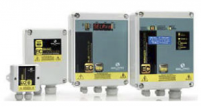
The VTS series three-phase regulators are built on a Vetronite(R)
support in an IP55 grade GW PLAST box. The control zone is at the
top of the board while the power zone is at the bottom.
In addition to the M3 and M4 terminal boards, regulation, connection
and signal devices are found in the control zone.
The fan speed command varies according to the command signal
received from the input. Output increases as input increases.
2.2. Key
VTS300 key
Wire clamps — connection wires
1
—
Three-phase output terminal board (U-V-W) + load
2
M1
GND
Three-phase power supply terminal board (L1-L2-
3
M2
L3) + PE
TPN lock screws with max 2.5 N m torque
4
—
Wall mount perforated fin
5
—
GW PLAST case
6
—
Minimum voltage settings (MIN / CUT-OFF)
7
P1
Maximum voltage settings (MAX)
8
P2
Command input terminal board
9
M3
Alarm relay terminal board
10
M4
Signal led
11
DL..
Programming dip switch (0-10Vdc std setting)
12
DSw
Reset button
13
SB1
SELPRO – Via P.G. Piamarta 5/11 – 25021 Bagnolo Mella (BS) – www.selpro.it – info@selpro.it — Tel. +39 030 6821611 – Fax +39 030 622274
2.3. Mechanical dimensions
Plate data
Mechanical dimensions
Model
A
kV A
IP
A
B
8
5.5
55
225
235
VTS308
12
8
55
225
230
VTS312
20
14
55
225
230
VTS320
* Packaging included
3. INSTALLATION
3.1. INSTALLATION
Vertically install the device with the wire inlet facing down. To permit
correct heat dissipation, guarantee ≥150 mm clearance over and under
the regulator.
Reassemble and make sure the external protection lid is fully closed.
3.2. Electrical connections
Flexible wire section.
Signal:
rated section 1.5 mm² (15 AWG)
Power:
VTS 308 ≥ 1.5 mm² (15 AWG)
VTS 312 ≥ 2.5 mm² (13 AWG)
VTS 320 ≥ 4.0 mm² (11 AWG)
N.B. Protection devices: see point 8.
3.2.1. Power (M1) and load (M2*) connection:
(*)The regulator can be set to directly connect no. 4 fans (Three-phase +
Ground) upon request
3.2.2. Command signal connections (M3)
M3
Terminal
Label
6
GND
Reference grounding
5
S0
ON-OFF input (see point 3.3.3)
Reference voltage output
4
VR
+5.0 Vdc/+10.0 Vdc (±1.0%)
(automatic switching)
Power supply voltage output
3
V+
+20 Vdc (±20%)
2
GND
Reference grounding
1
IN
Command signal input
3.2.3. Alarm relay connection (M4)
Weight(*)
C
E
F
Kg
114
213
200
2.3
128
213
200
2.5
158
213
200
3.8
3.3. Dip-Switch function settings (DSw1 – DSw6)
DSw
1,2,3
4
5,6
3.3.1. Default settings
3.3.2. Command input function programming
WARNING Press button SB1 after changing DSw settings to apply
changes..
DSw1
OFF
ON
OFF
ON
OFF
ON
3.3.3. Functional programming for the ON-OFF input (S0)
DSw5
OFF
ON
ON
OFF
4. FUNCTIONAL CHARACTERISTIC
Description
rev.3.1 dated 30/06/14
Termi
Label
Description
nal
3
NO
Normally open contact
Normally closed
2
NC
contact
1
COM
Shared terminal
Description
Command signal selection (see point 3.3.2)
OFF = P1 (MIN) minimum voltage settings
ON = P1 cut-off voltage settings
ON-OFF input function (see point 3.3.3)
DSw2
DSw3
Description
OFF
OFF
0-20 mA signal
OFF
OFF
4-20 mA signal
ON
OFF
0-10 Vdc signal
ON
OFF
0-5 Vdc signal
OFF
ON
PWM signal
ON
ON
Cos Phi calibration (reserved)
DSw6
Description
OFF
Start/Stop function (open = start)
OFF
Thermal contact function (closed = start)
ON
Output function at 100% (closed = 100%)
ON
Output function at MAX (closed = MAX (P2))
-
Contents
-
Table of Contents
-
Bookmarks
Quick Links
ESY 1~
User Manual
Specialized
Vac stepless Controllers
for
single-phase Asynchronous Motors
on Axial & Centrifugal Fans
ON
Ventilated Heat Exchangers
Drycoolers & Air Cooled Condensers
3
YEAR
FAN speed Control Solutions
Related Manuals for SELPRO ESY 1

Summary of Contents for SELPRO ESY 1
-
Page 1
ESY 1~ User Manual Specialized Vac stepless Controllers single-phase Asynchronous Motors on Axial & Centrifugal Fans Ventilated Heat Exchangers Drycoolers & Air Cooled Condensers YEAR FAN speed Control Solutions… -
Page 2: Precautions
WARNING ! HIGH LEAKAGE CURRENT First connect to Earth ! DO NOT touch the electrical parts of the circuit when the power supply is connected under any circumstances Safety Warnings • We disclaim all responsibility for accident, loss or damage caused by the use of these appliances. These must be correctly installed by qualified personnel in conformity with their intended use and, whenever needed, must undergo correct maintenance which should be carried out while ensuring the safety of people, domestic animals and goods.
-
Page 3: Table Of Contents
ELECTRICAL CONNECTIONS ………………….Errore. Il segnalibro non è definito. 5.1. Power Supply Connection (Terminal Block M1) ……………………….7 SIGNAL CONNECTIONS for the 4 CONFIGURATIONS (ALL-in-ONE) ………………..8 6.1. OM CONFIGURATION (STANDARD SELPRO) ……………………….8 6.2. OX Configuration (on request) …………………………….8 6.3. OV Configuration (on request) …………………………….9 6.4.
-
Page 4: Ec Directives & Technical Standards
EC DIRECTIVES & TECHNICAL STANDARDS This series has been designed and manufactured for use in industrial environments, and complies therefore with the following European Directives: • Machine Directive 98/37 CE and following amendments • Low Voltage Directive (LVD) 2006/95/EC • EMC Directive 2004/108/EC Thanks to its advanced technical solutions, the ESY100 series has obtained the CE mark in compliance with the EMC (Electromagnetic Compatibility) directive 2004/108/EC also in household environment.
-
Page 5: Operating Modes And Applications
3. OPERATING MODES AND APPLICATIONS The ESY1 devices are electronic analog regulators of single-phase AC voltage, which use the phase-cutting principle (Triac) in order to vary the output active voltage applied to a resistive or inductive load. When connected to asynchronous high-slip electric motors of fans or pumps, they control their rotational speed in order to maintain the key parameter within desired values.
-
Page 6: Technical Characteristics Esy-1
4. TECHNICAL CHARACTERISTICS ESY-1 Voltage 230V ± 10 % single phase – (on request 110V — 400V Frequency 50Hz standard (60 Hz only factory calibration) OWER UPPLY Overvoltage Protection for installation Category II (4 KV) Electronic analog regulators of single-phase AC voltage, which use the phase-cutting principle (Triac) in order to vary the PERATING output active voltage applied to a resistive or inductive load.
-
Page 7
Transducer voltage supply 22V (+10/-20%) max. 25mA Transducer voltage supply 22V (+10/-20%) max. 25mA Config. + 10V Transducer voltage supply 10,0V (±1%) Output signal for slave unit: 0-10Vdc or PWM (MAX 5 modules) Transducer voltage supply 22V (+10/-20%) max. 25mA Transducer voltage supply 22V (+10/-20%) max. -
Page 8: Electrical Connections
5. ELECTRICAL CONNECTIONS Connect the controller as shown in the figure below, paying attention to the following points 5.1. Power Supply Connection (Terminal Block M1) -Before supplying power to the unit, check carefully the power connection and the efficiency of EARTH connection. -Ensure that power conductors and EARTH CABLES have a cross section suitable to the connected load.
-
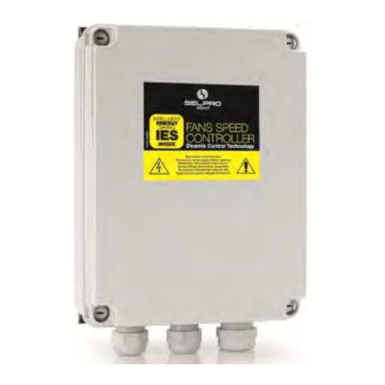
Page 9: Signal Connections For The 4 Configurations (All-In-One)
— SLAVE, using the input In4 ( for 0-10V control signal) The controllers of the ESY-1/ALL-in-ONE series can be set in the following four (4) configurations, described below. The OM configuration is standard SELPRO 6.1. OM CONFIGURATION (STANDARD SELPRO) N°…
-
Page 10: Ov Configuration (On Request)
6.3. OV Configuration (on request) N° Name Function CONF. Output voltage supply + 5,0V ±1% Transducer Input 0-5 Vdc N° 1 Ground Transducer Input 0-5 Vdc N° 2 Output voltage supply + 5,0V ±1% Transducer Input NTC 10kohm N° 3 @ 25°C Ground Input N°…
-
Page 11: Electrical Connection For Slave Module/S
7. Electrical connection for Slave Module/s The controllers of the ESY-1 / ALL-in-ONE series include moreover the SLAVE-ONE power units, in the two following versions: SLAVE-SV with input for 0-10Vdc control signal SLAVE-SP with input for PWM control signal All the models of the series share the same technical characteristics and are available in different sizes: 8 A –…
-
Page 12: Connection Of Slave Modules, Sp Series (Pwm Power Units)
7.3. Connection of SLAVE modules, SP series (PWM power units) The SLAVE-SP unit allows the connection of the only PWM (PPM-Triac) control signal. The input is optimized in order to be compatible with every device having a PWM control signal, from 5V to 30V. All connected SLAVE-SP units require the same supply phase as the remote controller, which generates the PWM control signal (network synchronization) SLAVE –…
-
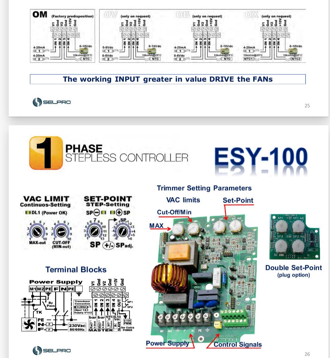
Page 13: Esy-1: Control & Power Card In Detail, All-In-One Version
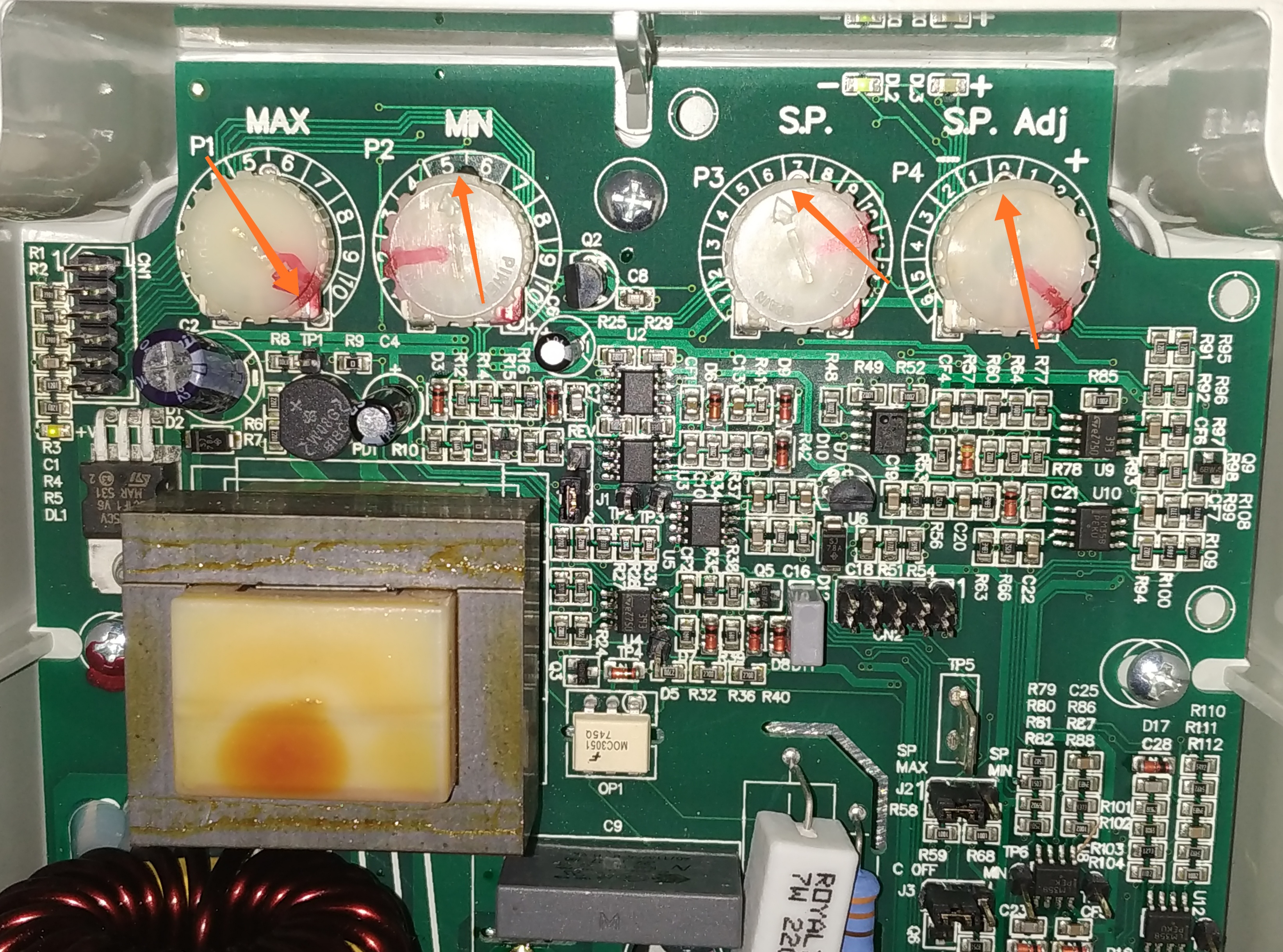
8. ESY-1: CONTROL & POWER CARD IN DETAIL, ALL-in-ONE version Led Led Led Led MAX OUT SPadj CUT-OFF (MIN OUT ) SP1adj SP2adj Double Set-Point optional card Jumper Description ESY-1 / ALL-in-ONE & LED DIRECT-REVERSE mode selection VAC Output at SET-POINT CUT-OFF / MIN OUT selection EXTRA-power control Output Power supply O.K.
-
Page 14: Led Signals
LED signals 8.2. The cards present LED signals, which point out the state and the operation of the controller. The LED signals of the complete version ESY-1 / ALL-in-ONE are shown in the table below: 230Vac Green LED Power supply O.K. Green LED SP higher than the signal value 100%…
-
Page 15: Set-Up Of Operating Limits And Parameters
9. Set-up of operating LIMITS and PARAMETERS 9.1. Available regulations in the standard ESY-1 version (ALL-in-ONE) The ESY-1 controllers present two regulation Trimmers for setting up the operating limits (MIN out / Cut-Off and MAX out), the automatic regulation performs the variations of fans speed, and a couple of 13-positions rotary switches for setting up the SET-Point of reference with ease.
-
Page 16: How To Set Up The Operating Limits For Slave-One Modules (Only Slave-Sv Version)
9.3. How to set up the operating limits for SLAVE-ONE modules (only SLAVE-SV version) The following procedures allow to set up the AC voltage limits, within which the 0-10 Vdc control signal is automatically controlled. It allows to set up manually the minimum AC output voltage MIN Vac supplied to the fan, from 20% to 90%, and permits to check: — the correct phase-cutting of the controller…
-
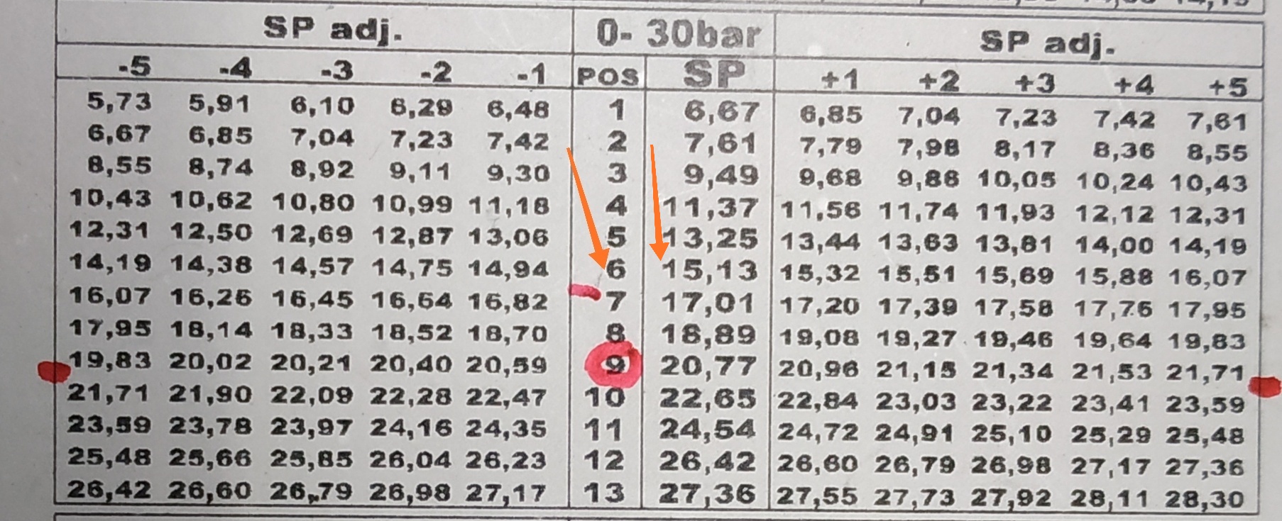
Page 17: Tables For The Set-Point Selection
After selecting the operating modes and setting up the operating limits, it is necessary to determine the operating point of the regulation: the SET-POINT, on the basis of the scales and ranges referring to the connected sensor (*). The Set-Point is easily and quickly fixed through the couple of 13-position rotary switches, named as follows: SP (main reference point for the regulation) and SPadj.
-
Page 18: Set Point Values, Range 0-25 Bar (Transducer 4-20 Ma)
12,74 12,83 12,93 13,02 13,11 13,21 13,30 13,40 13,49 13,58 13,68 12,69 13,73 13,16 13,21 13,30 13,40 13,49 13,58 13,68 13,77 13,87 13,96 14,05 14,15 14,20 9.5.3. Set Point values, range 0-25 bar (Transducer 4-20 mA) 0-25 bar adj. adj. 4,69 4,77 4,93…
-
Page 19: Set-Point Values, Range 0-45 Bar (Transducer 4-20 Ma)
9.5.5. Set-Point values, range 0-45 bar (Transducer 4-20 mA) 0-45 bar adj. adj. 8,45 8,59 8,87 9,15 9,43 9,72 10,00 10,28 10,56 10,85 11,13 11,41 11,55 10,00 10,28 10,56 10,85 11,13 11,41 11,69 11,97 12,26 12,54 12,82 9,86 12,96 12,82 13,10 13,38 13,67…
-
Page 20: Set-Point Values, Range 10°C To 60°C (Ntc Probe 10Kohm@25°C)
9.5.7. Set-Point values, range 10°C to 60°C (NTC probe 10kohm@25°C) 10-60 °C adj. adj. 2,00 2,50 3,00 3,50 4,00 4,50 5,50 6,00 6,50 7,00 7,50 8,00 7,50 8,00 8,50 9,00 9,50 10,50 11,00 11,50 12,00 12,50 7,00 13,00 12,50 13,00 13,50 14,00 14,50…
-
Page 21: Function Diagrams & Operating Parameters In Master & Slave Modes
10. Function diagrams & Operating parameters in MASTER & SLAVE modes Standard values of the proportional band (Pb): transducer 4-20 mA Pb=2.5 mA, transducer 0-5 Vdc Pb=0,65 Vdc, sensor NTC 10kohm@25°C Pb=7.0°C Min= Off= Vac= =fans maximum rpm — fans minimum rpm — fans off — voltage supply to the load;…
-
Page 22: Accessories
11. ACCESSORIES 11.1. Manual Remote Control Units ♦ Series of potentiometers for manual remote control Potentiometer for external remote control Manual speed setting with 0-10 Vdc Available 1 & 10 turn versions, with standard knob ∅ ∅ ∅ ∅ 22 and silk screen label Available 10 turn version, with knob ∅…
-
Page 23: Pressure Transducer For 4-20 Ma & 0-5 V
11.2 Pressure Transducer for 4-20 mA & 0-5 V Description 4-20 mA 0-5 Vdc Control signal 4 … 20 mA 0,5 … 4,5 V Power supply 8 … 28 V 5 V +/- 0,25V Range (bar) 0 … 15/25/30/45 0 … 30/45 Linearity <…
-
Page 24
TECHNICAL ASSISTANCE FORM 1. All ESY-1 equipments are guaranteed for 36 months from the date of testing. 2. The guarantee will be rendered invalid under these circumstances: • evidence of tampering with the mechanical or electrical parts • improper use •… -
Page 25
Via P. G. Piamarta, 5/11 Tel. (+39) 030.6821611 info@selproweb.com 25021 Bagnolo Mella (Bs) Fax (+39) 030.622274 www.selproweb.com User Manual ESY-1 / rev. 9 15.01.2008 www.selproweb.com…
-
14.05.2022, 13:48
#1

Местный

 Регулятор мощности S.EL.PRO. MODEL: DRV312-42-5-0-c-s спалил 3 FAN. Почему — ?
Регулятор мощности вентиляторов S.EL.PRO.
MODEL: DRV312-42-5-0-c-s управляет тремя вентиляторами, включенными параллельно — 220V.В течение 1 года разные вентиляторы 3 шт. вышли из строя, каждый в свое время.
Местный техник утвержает, что неисправен S.EL.PRO.
Я считаю, что частотник исправен, т.к. в течение 1 года поддерживает Pk=18 Бар зимой и летом.Кто прав?
Аналогичная тема.
https://holodforum.ru/showthread.php…BD%D0%B8%D0%BA
-
16.05.2022, 16:36
#2

Мастер
Возможно на частотнике или контроллере сделаны неправильные настройки
-
16.05.2022, 17:13
#3
Местный
 Сообщение от Сергей Р

Возможно на частотнике или контроллере сделаны неправильные настройки
Какие настройки неправильные,
если Pk в норме зимой и летом?
-
16.05.2022, 17:35
#4
Пользователь
Сообщение от FBT
Какие настройки неправильные,
если Pk в норме зимой и летом?А причем тут настройки Pk и настройки вентиляторов? Вы путаете теплое с мягким.
-
16.05.2022, 19:03
#5
Местный
Сообщение от Hell-Hound
А причем тут настройки Pk и настройки вентиляторов? Вы путаете теплое с мягким.
Потому что крутилка Fan дает стабильное Pk.
Больше ничего.
Контроллер не при чем.
Управление крутилкой с трансдюссера на Pk.
-
20.12.2022, 04:07
#6
Местный
Сообщение от Сергей Р
Возможно на частотнике или контроллере сделаны неправильные настройки
Настройка регулятора SELPRO.
-
20.12.2022, 04:32
#7
Местный
-
20.12.2022, 05:16
#8
-
20.12.2022, 07:50
#9
Мастер
Сообщение от FBT
Регулятор мощности вентиляторов S.EL.PRO.
MODEL: DRV312-42-5-0-c-s управляет тремя вентиляторами, включенными параллельно — 220V.В течение 1 года разные вентиляторы 3 шт. вышли из строя, каждый в свое время.
Местный техник утвержает, что неисправен S.EL.PRO.
Я считаю, что частотник исправен, т.к. в течение 1 года поддерживает Pk=18 Бар зимой и летом.
Кто прав?А, давай, повангую?
Вентиляторы стоят вертикально.
-
20.12.2022, 08:02
#10
Местный
Сообщение от SSA
А, давай, повангую?
Вентиляторы стоят вертикально.Нет, два одинаковых кондея UNIFLAIR, одинаково нагруженные.
В одном часто летят вентиляторы, в другом — нет. У обоих горизонтальные конденсаторы.
-
20.12.2022, 09:27
#11
Мастер
-
20.12.2022, 09:37
#12
Местный
Сообщение от SSA
Датчик менял?
Спасибо за правильный вопрос.
Два датчика (2 контура в 1 конденсаторе с 3 FAN) сдохнуть не могут.
Посмотрю, сравню,
резик в параллель потыкаю.
-
20.12.2022, 16:45
#13
Мастер
Там же, вроде, можно вместо токового датчика 0-20 mA поставить потенциометр вместо датчика NTC.
-
27.07.2023, 09:13
#14
Местный
Сообщение от FBT
Почему Pk=23 Bar (R22) — ?
Заправка в норме, проверено=48 кг,Потому, что грязный конденсатор.
На просвет небо видно,
техники клянутся — мыли недавно.Промывка конденсатора:
1 — демонтаж FAN (3 шт),
2 — смачивание конденсатора водой из шланга — вода черная,
3 — разбрызгивание опрыскивателем SUPER CLEANER 1:4 по инструкции — пена черная, пузыри черные,
3 — перекур 10 мин
4 — тщательная промывка водой из керхера 150 Бар — до пропадания пузарей и чистой воды.
Керхероом иыть противоположно напрaвлению влздухa FAN.Итого:
100 минут мойка конденсатора.Результат:
Pk=18 Бар
при Тул=+25С
Ufan= AC 230V.
Заправка — R22=38 кг.
-
27.07.2023, 10:22
#15
Местный
Сообщение от FBT
Спасибо за правильный вопрос.
Два датчика (2 контура в 1 конденсаторе с 3 FAN) сдохнуть не могут.
Посмотрю, сравню,
резик в параллель потыкаю.Aналог трансдюссера:
Pk=20Bar (4…20 mA).R=500 Ohm /025W.
U=13 V / 25 mA => FAN Vmax. (AC U=230V).
Социальные закладки
Социальные закладки
-

Google

Ваши права
- Вы не можете создавать новые темы
- Вы не можете отвечать в темах
- Вы не можете прикреплять вложения
- Вы не можете редактировать свои сообщения
- BB коды Вкл.
- Смайлы Вкл.
- [IMG] код Вкл.
- [VIDEO] код Вкл.
- HTML код Выкл.
Правила форума

rev.3.1 dated 30/06/14
VTS300 3-PHASE SLAVE REGULATOR
SELPRO – Via P.G. Piamarta 5/11 – 25021 Bagnolo Mella (BS) – www.selpro.it – [email protected] — Tel. +39 030 6821611 – Fax +39 030 622274
1. PREPARATIONS
1.1. Important
Read these instructions carefully before installation.
Before use, follow all the installation and electrical connection
instructions.
Keep these instructions with the regulator for future use.
Observe current technical and safety regulations.
The device must be professionally installed and commissioned by a
qualified technician. INCORRECT installation may cause damages.
Before turning on device power, always check that it is correctly
grounded.
DO NOT tamper with or REMOVE internal regulator components;
this NULL AND VOIDS THE WARRANTY and can cause damages.
The user must be protected against electrical shock and the motor
must be equipped with overload protection, as per current pertinent
regulations.
According to safety regulations, protection against any contact with
live parts must be ensured by correct device installation; all parts
that ensure protection must be secured so as irremovable without
the help of a tool.
DO NOT turn on the regulator without the protection lid.
NEVER touch electrical circuit parts when the power is on.
Install the regulator away from direct sunlight so as not to overheat
the case.
Make sure working conditions (working temperature, humidity, etc.)
are within the indicated limits (see point 7).
Do not install the device near heat sources (resistances, hot air
ducts, etc.) where room temperature can exceed 50 °C, devices
that generate strong magnetic fields, sites subject to rain, humidity,
dust, excessive mechanical vibrations or shocks.
2. VTS300 REGULATOR UNIT DESCRIPTION
2.1. Overview
The VTS series three-phase regulators are built on a Vetronite(R)
support in an IP55 grade GW PLAST box. The control zone is at the
top of the board while the power zone is at the bottom.
In addition to the M3 and M4 terminal boards, regulation, connection
and signal devices are found in the control zone.
The fan speed command varies according to the command signal
received from the input. Output increases as input increases.
2.2. Key
VTS300 key
1 — Wire clamps — connection wires
2 M1 Three-phase output terminal board (U-V-W) + load
GND
3 M2 Three-phase power supply terminal board (L1-L2—
L3) + PE
4 — TPN lock screws with max 2.5 N m torque
5 — Wall mount perforated fin
6 — GW PLAST case
7 P1 Minimum voltage settings (MIN / CUT-OFF)
8 P2 Maximum voltage settings (MAX)
9 M3 Command input terminal board
10 M4 Alarm relay terminal board
11 DL.. Signal led
12 DSw Programming dip switch (0-10Vdc std setting)
13 SB1 Reset button
2.3. Mechanical dimensions
Model
Plate data Mechanical dimensions Weight(*)
A kV A IP A B C E F Kg
VTS308 8 5.5 55 225 235 114 213 200 2.3
VTS312 12 8 55 225 230 128 213 200 2.5
VTS320 20 14 55 225 230 158 213 200 3.8
* Packaging included
3. INSTALLATION
3.1. INSTALLATION
Vertically install the device with the wire inlet facing down. To permit
correct heat dissipation, guarantee ≥150 mm clearance over and under
the regulator.
Reassemble and make sure the external protection lid is fully closed.
3.2. Electrical connections
Flexible wire section.
Signal: rated section 1.5 mm² (15 AWG)
Power: VTS 308 ≥ 1.5 mm² (15 AWG)
VTS 312 ≥ 2.5 mm² (13 AWG)
VTS 320 ≥ 4.0 mm² (11 AWG)
N.B. Protection devices: see point 8.
3.2.1. Power (M1) and load (M2*) connection:
(*)The regulator can be set to directly connect no. 4 fans (Three-phase +
Ground) upon request
3.2.2. Command signal connections (M3)
M3 Terminal Label Description
6 GND Reference grounding
5 S0 ON-OFF input (see point 3.3.3)
4 VR
Reference voltage output
+5.0 Vdc/+10.0 Vdc (±1.0%)
(automatic switching)
3 V+
Power supply voltage output
+20 Vdc (±20%)
2 GND Reference grounding
1 IN Command signal input
3.2.3. Alarm relay connection (M4)
Termi
nal
Label Description
3 NO
Normally open contact
2 NC
Normally closed
contact
1 COM
Shared terminal
3.3. Dip-Switch function settings (DSw1 – DSw6)
DSw Description
1,2,3 Command signal selection (see point 3.3.2)
4
OFF = P1 (MIN) minimum voltage settings
ON = P1 cut-off voltage settings
5,6 ON-OFF input function (see point 3.3.3)
3.3.1. Default settings
3.3.2. Command input function programming
WARNING Press button SB1 after changing DSw settings to apply
changes..
DSw1 DSw2 DSw3
Description
OFF OFF OFF 0-20 mA signal
ON OFF OFF 4-20 mA signal
OFF ON OFF 0-10 Vdc signal
ON ON OFF 0-5 Vdc signal
OFF OFF ON PWM signal
ON ON ON Cos Phi calibration (reserved)
3.3.3. Functional programming for the ON-OFF input (S0)
DSw5 DSw6
Description
OFF OFF Start/Stop function (open = start)
ON OFF Thermal contact function (closed = start)
ON ON Output function at 100% (closed = 100%)
OFF ON Output function at MAX (closed = MAX (P2))
4. FUNCTIONAL CHARACTERISTIC
EC-двигатель регулятор / вентилятор — SELPRO
ЕС серия-это полноценный и современный технологический регламент устройства высшую работоспособность EC-двигателями применяется в вентиляторах. Данный системы позволяют модификация системы вентиляции согласно оперативным требованиям энергоэффективности активизировать внутренний потенциал Эко-питания вентиляторов. SELPRO имеет партнерские отношения с ЛЮВЭЙ-группы и EBM-papst, чтобы обеспечить систему регулятора с одного плюс
Есть вопросы?
Вы можете задать их менеджерам наших партнеров прямо сейчас!
Задать вопрос