Hide thumbs
Also See for D1000:
- Manual (35 pages)
-
Contents
-
Table of Contents
-
Troubleshooting
-
Bookmarks
Quick Links
Related Manuals for FAAC D1000
Summary of Contents for FAAC D1000
-
Page 1
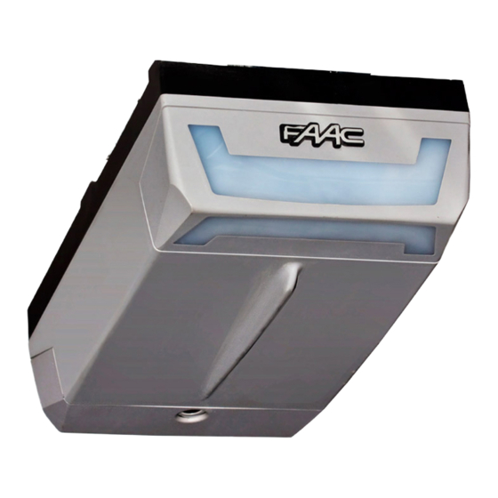
D1000 D1000… -
Page 2
Leggere completamente questo manuale di istruzioni prima di iniziare l’installazione del prodotto. Il simbolo evidenzia le note importanti per la sicurezza delle persone e l’integrità dell’automazione. Il simbolo richiama l’attenzione sulle note riguardanti le caratteristiche od il funzionamento del prodotto. Read this instruction manual to the letter before you begin to install the product. -
Page 3: Table Of Contents
Index GENERAL SAFETY INSTRUCTIONS FOR INSTALLATION AND MAINTENANCE ……..p. 2 TOOLS AND MATERIALS ……………………p. 2 DECLARATION OF CONFORMITY ………………….p. 3 WARNINGS FOR THE INSTALLER ………………….p. 3 1. DIMENSIONS ……………………….. p. 4 2. TECHNICAL SPECIFICATIONS ………………….p. 4 3.
-
Page 4: General Safety Instructions For Installation And Maintenance
50 mm laid on the ground, must be correctly detected. IMPORTANT! DANGER OF CRUSHING. •If the power cable of operator D1000 is damaged, it must be replaced by qualified personnel, using a new cable of the same type. Do not use different power cables.
-
Page 5: Declaration Of Conformity
19) Do not in any way modify the components of the automated a source of danger. system. 6) FAAC declines all liability caused by improper use or use other than 20) The installer shall supply all information concerning manual operation that for which the automated system was intended.
-
Page 6: Dimensions
AUTOMATED SYSTEM D1000 These instructions apply to model FAAC D1000. 2. TECHNICAL SPECIFICATIONS The D1000 automated systems make it possible to automate balanced sectional doors of single garages for residential Model D1000 use. Power supply (V ~ / 50 Hz.)
-
Page 7: Description
4. DESCRIPTION Ceiling lamp Rear door Courtesy light Plastic housing for D1000 operator Rear fitting Sliding guide Drive carriage Release knob Door fitting bracket Transmission unit Front fitting and chain tensioner Fig. 3 Front fitting bracket 5. PRELIMINARY CHECKS have been installed.
-
Page 8: Assembly
2) Slide the transmission unit (Fig.7 ref. A) along the whole sliding 6. ASSEMBLY guide, until it is near the front terminal, the one opposite the 6.1. Sliding guide drive coupling. 3) Assemble the front fitting (Fig. 7 ref. B) to the transmission unit If you use a sliding guide in two pieces, you must assemble it, (Fig.
-
Page 9: External Release (Optional)
6.3. External release (optional) 7.1. Sliding guide If the external release system has to be installed, the cable When you have finished the preliminary assembly operations, must be placed in its seat before beginning to install. you can begin installing the sliding guide, as follows: 1) Release the carriage (see par.
-
Page 10: On-Door Fitting
 Lift the sliding guide until the rear fitting is at the same level Position the fitting on the door so that the through-element as the front fitting, or until you reach the same inclination as of the release cable is facing toward the left side of the door the door’s horizontal rail.
 -
Page 11: Operator
7.3. Operator When you have assembled the rear fitting to the sliding guide and finished installing the sliding guide, you can install the operator: 1) While keeping the operator inclined at 15/20° (Fig. 20), insert the gearmotor shaft in the coupling on the rear fitting of the sliding guide and make the fins (Fig.
-
Page 12: E1000 Control Board
8. E1000 CONTROL BOARD 8.1. Technical specifications 230 / 50 Supply voltage (V ~ / Hz.) Power supply to accessories (Vdc) Accessories max. load (mA.) -20 / +55 Operating ambient temperature (°C) for receiver boards XF433 / Quick-fit connector XF868 and battery module Automatic / Semiautomatic Operating logics Open/Stop/Safety devices/Fail-…
-
Page 13: Courtesy Light
During the closing manoeuvre, it opens — The D1000 operator has a cable with a two-pole plug for 230 the door. Vac power supply. — To connect the external controls, safety devices and signals, If, during closure, an obstacle is detected more than break open the pre-holed element (Fig.
-
Page 14: Programming
— the force required to move the door. 11. PROGRAMMING — the slow-down points. 11.1. Setting the board — the opening and closing stop points. — the pause time (in automatic logic). Set the appliance with Dip-Switch DS1 to obtain the operation you require, referring to chapter 8.4.
-
Page 15
During these 5 seconds, in order to lighten the load on the 1) Give the 1st OPEN command: the operator performs a release system, you can send OPEN pulses within a time interval deceleration closing manoeuvre until it detects the stop of 2 seconds from each other, in order to reverse the carriage. -
Page 16: Pre-Flashing
11.3 Pre-flashing The pre-flashing function can be enabled and disabled (following an OPEN command, the unit activates the flashing lamp for 5 seconds before it starts the movement). Procedure: 1) Press and hold down the SET UP push-button. 2) Press the OPEN push-button too after about 3 seconds. If the SET UP LED goes ON, pre-flashing was activated, if instead, it stays OFF, pre-flashing was disabled.
-
Page 17: Memory Storage Of Radio Controls Lc (For Some Markets Only)
— Quickly press twice in succession the memory stored radio control push-button All codes of radio controls stored as OPEN A and OPEN B will be deleted. The automated system performs one opening operation. 13. START-UP Make sure that the automated system is free of any obstacle created by persons or things.
-
Page 18: Parachute Cables
16 . REPAIRS — House the control unit as shown in Fig. 36. — First hook on the two fastening clips on the coupling on the For repairs, contact FAAC’s authorised Repair Centres.17.1. base. Central support — Then press lightly until you can hear the hooking snap sound.
-
Page 19: Troubleshooting
18 . TROUBLESHOOTING Trouble Possible causes Solution When the learning procedure is started, The STOP and FSW safety devices are the SET UP LED flashes but the automated enabled also during the learning stage. system does not perform any Non-connection or wrong connection manoeuvre prevents the operator from working Check the LEDs’…
This manual is also suitable for:
D600
![]()
FAAC D600/D1000 Привод для гаражных ворот — Инструкция по установке и эксплуатации в формате pdf. Руководства по установке, настройке и эксплуатации оборудования.
Дата добавления: 10.08.2009
Размер файла: 1.7Mb
Формат файла: pdf
Просмотров: 4849
Загрузок: 1482
Дополнительная информация
Отзывы и комментарии
Отзывы и комментарии к материалу «FAAC D600/D1000 Привод для гаражных ворот — Инструкция по установке и эксплуатации».
- Home
- Инструкции
- Автоматика для ворот
- FAAC
- D1000
FAAC D1000 инструкция
Язык: Русский
Размер : 1.7 Mb
Формат файла: pdf
Добавлен: 04.06.2013
Руководство по установке и использованию
Автоматика для ворот FAAC
Похожие записи
FAAC D1000 (E1000) — Схема электрическая принципиальная
Автоматика для ворот
Отзывы по оборудованию и комментарии к материалу
Ответить 06.12.2017 05:54
Владимир
Класс
Кто вы? человек робот
Автоматические и технические устройства от всемирно известной итальянской компании FAAC безопасны, комфортны, характеризуются современным дизайном и самым совершенным оснащением. Разнообразные электромеханические приводы, платы управления, автоатизированные шлагбаумы, системы для распашных ворот, радиоканалы, двухканальные детекторы индуктивных петель имеют подробные и понятные руководства, написанные специалистами. Здесь у Вас есть возможность скачать и изучить инструкции по монтажу, настройке и эксплуатации, что существенно упростит использование.
- FAAC 415 привод распашных ворот
- FAAC 720 привод откатных ворот
- FAAC 740-741 привод откатных ворот
- FAAC_540 привод секционных ворот
- FAAC_E024S_391 блок управления
- Описание приводов FAAC
- FAAC 531-576 привод секционных ворот
- FAAC 620-640 — инструкция по установке
- FAAC 844 привод откатных ворот
- FAAC 868 SLH радиоканал
- FAAC SAFEBEAM фотоэлементы
- FAAC_ 391 привод распашных ворот
- FAAC_ 620-640 шлагбаум
- FAAC_ 620RPD шлагбаум
- FAAC_ 620STD шлагбаум
- FAAC_ 620TT шлагбаум
- FAAC_ 624 BLD блок управления
- FAAC_ 640 шлагбаум
- FAAC_ 642 шлагбаум
- FAAC_ 884 привод откатных ворот (промышленный)
- FAAC_400 привод распашных ворот
- FAAC_412 привод распашных ворот (2)
- FAAC_412 привод распашных ворот
- FAAC_415 привод распашных ворот
- FAAC_422 привод распашных ворот
- FAAC_433LC радиоканал
- FAAC_452MPS блок управления
- FAAC_596_615BPR блок управления
- FAAC_615 шлагбаум
- FAAC_620SR шлагбаум
- FAAC_741 привод откатных ворот
- FAAC_746 привод откатных ворот
- FAAC_D600 привод секционных ворот
- FAAC_D1000 привод секционных ворот
- FAAC_DP2 детектор индуктивных петель
- FAAC_E624 блок управления
- FAAC_E700 блок управления
- FAAC_E720 блок управления
- FAAC_XP15W фотоэлементы
- Процедура замены масла шлагбаумов
Автоматический электропривод FAAC D1000 используется для автоматизации сбалансированных гаражных секционные ворот гаражей для жилых домов.
- Конструкция ворот должна подходить для установки на автоматизированную систему. А именно, проверьте, соответствуют ли размеры ворот указанным размерам в технических условиях, и что они достаточно прочные и иметь свободный отбалансированный ход.
- Убедитесь в отсутствии трения при движении ворот. При необходимости проведите чистку и смажьте шарниры роликов средством на основе силикона, однако не используйте смазку и всегда придерживайтесь инструкций производителя.
- Проверьте баланс (пружины) и наличие установленных механических ограничителей открывания.
- Снимите существующий механизм закрывания ворот, чтобы обеспечить возможность закрытия ворот автоматизированной системой.
- Убедитесь в наличии зазора минимум в 50 мм между потолком и высшей точкой движения ворот.
- Проверьте, находится ли верхний направляющий ролик секционных ворот в горизонтальной части направляющей, когда ворота закрыты
Всторенный блок управления FAAC E600 имеет разъем быстрого подключения для приемников XF433 или XF868 используемых для дистанционного управления приводом.