- Manuals
- Brands
- Johnson & Johnson Manuals
- Medical Equipment
- Ethicon Endo-Surgery ULTRACISION HARMONIC…
- Service manual
-
Contents
-
Table of Contents
-
Bookmarks
Quick Links
U
C
®
H
S
®
Service Manual
LTRA
ISION
ARMONIC
CALPEL
Related Manuals for Johnson & Johnson Ethicon Endo-Surgery ULTRACISION HARMONIC SCALPEL
Summary of Contents for Johnson & Johnson Ethicon Endo-Surgery ULTRACISION HARMONIC SCALPEL
-
Page 1
® ® Service Manual LTRA ISION ARMONIC CALPEL… -
Page 2
® ® Service Manual LTRA ISION ARMONIC CALPEL Table of Contents Chapter 1 — General Description 1.1 — The U System LTRA ISION ARMONIC CALPEL Chapter 2 — Principles of Operation 2.1 — Hand Piece 2.2 — Generator and Foot Switch Chapter 3 — Basic Operation 3.1 — Description of Controls, Indicators, and Connections 3.2 — Instrument Preparation and Hand Piece Attachment… -
Page 3
® ® Service Manual LTRA ISION ARMONIC CALPEL Table of Contents — continued Appendix A — Diagnostic Service Mode — Flow Diagram Appendix B — Wiring Diagrams and Schematic 115 Volt Wir ing (Model GEN01) 230 Volt Wiring (Models GEN22, GEN32) 115 Volt Routing (Model GEN01) 230 Volt Routing (Models GEN22, GEN32) Generator PCB Schematic… -
Page 4: Chapter 1 — General Description
Chapter 1 — General Description The U System is indicated for incising tissue when bleeding control and minimal LTRA ISION ARMONIC CALPEL thermal injury are desired. The System’s instruments can be used as an adjunct to or substitute for electrosurgery and steel scalpels.
-
Page 5
Chapter 2 — Principles of Operation continued • Low Voltage Transformer: produces low voltage AC that is later rectified, filtered, and regulated to produce Generator and +5 VDC, +12 VDC, and -12 VDC. It also provides an important safety barrier. The voltage generated on the Foot Switch secondary of the transformer is isolated — i.e. -
Page 6
Chapter 2 — Principles of Operation continued Generator System Overview… -
Page 7: Chapter 3 — Basic Operation
Chapter 3 — Basic Operation Controls, Indicators, and Connections ULTRACISION GENERATOR ETHICON ENDO-SURGERY 5 4 3 2 1 STANDBY SAVE READY VARIABLE FULL Note: This illustration shows Generator Model GEN01. In Model GEN32, the position of the air and electrical connectors is reversed. Component Description Power Switch…
-
Page 8
Chapter 3 — Basic Operation continued Status Lights Ready Light. This light is illuminated when the system is ready to use. This light is off while the Hand Piece is energized or in STANDBY mode. Controls, Indicators, and Variable Light. This light is flashed on and off when the Hand Piece is energized at the Connections variable (VAR) power level. -
Page 9
Chapter 3 — Basic Operation continued Attach the sterile U Hand Piece following the ® ® LTRA ISION HARMONIC CALPEL Instrument appropriate package insert instructions: Preparation and Hand Piece Note: Refer to specific instrument package inserts for use of the Generator during surgical cases. Attachment continued Attach an instrument blade to the Hand Piece following the instructions listed in the… -
Page 10: Chapter 4 — Initial Setup
Chapter 4 — Initial Setup Two features of the system are user programmable. They are the displayed language and line rate. System The system may be configured to display messages in languages other than the default setting of English. These Configuration languages are French, Spanish, Italian, and German.
-
Page 11
Chapter 5 — Upper Level Diagnostics continued Symptom: Trouble Shooting The instrument blade fails to cut or coagulate or has less power than usual, Guide, continued and the Generator emits intermittent beeps when the Hand Piece is activated. Probable cause Corrective Action Instrument blade is not attached securely After pushing the Standby Button on the Generator,… -
Page 12
Chapter 5 — Upper Level Diagnostics continued Symptom: Trouble Shooting The Generator will not enter READY mode from STANDBY mode. Guide, continued Probable cause Corrective Action Foot Switch pedal is depressed while Release all pedals and switches while entering pushing Standby Button. READY mode. -
Page 13
Chapter 5 — Upper Level Diagnostics continued Symptom: Trouble The Generator display reads, “STOP! CHECK HAND PIECE — TURN OFF, THEN ON” and Generator Shooting Guide, emits long and short beeps. continued Probable cause Corrective Action Hand Piece connection to Generator Turn Generator Power Switch off, check to see that electrical is faulty. -
Page 14
Chapter 5 — Upper Level Diagnostics continued The green power LED located on the keyboard PCB is driven from the +5 VDC supply on the generator Diagnostic PCB. The most likely mode of failure is no AC voltage leading to the Generator PCB. If no other generator Software, activity is noticeable (i.e. -
Page 15
Chapter 5 — Upper Level Diagnostics continued • Random characters: Diagnostic Random or nonsense characters usually indicate a faulty microprocessor PCB. Software, Replace the microprocessor and re-test (see section 6.3.8). continued In both cases above, if the display still does not work properly, refer to section 6.3.9 and replace it. 4. -
Page 16
Chapter 5 — Upper Level Diagnostics continued Return to the second page of the service mode and review the error history list as follows: Diagnostic Software, Turn the Generator off. Access page one of the service mode by holding in the Increase and Decrease continued buttons at power up. -
Page 17: Chapter 6 — Detailed Diagnostics
Chapter 5 — Upper Level Diagnostics continued Activate the instrument blade by pressing the foot switch pedal labeled VAR. Verify that the VAR LED Extended flashes and that the Generator Audio Annunciator beeps. Activate the instrument blade by pressing the Functional Test, foot switch pedal labeled FULL.
-
Page 18
Chapter 6 — Detailed Diagnostics continued The following is a list of the equipment required in order to perform this level of testing: Test Equipment A digital voltmeter (FLUKE model 45 or equivalent) with insulated test probes and clips. A dual channel oscilloscope with x10 probes. An autotransformer adjusted for nominal line voltage (115 or 230 volts). -
Page 19: Chapter 6 — Detailed Diagnostics — Figure
Chapter 6 — Detailed Diagnostics — Figure 3 Hand Piece Pin Descriptions Hand Piece Models HP050, HP051, HPTUV, H1TUV (DRAIN) POWER (DRAIN) (BROWN) RETURN (BLACK) (DRAIN 2) (DRAIN 2) RETURN POWER (BLACK) (BROWN) CONNECTION CONNECTION CONNECTION SENSE SENSE (ORANGE) (ORANGE) DOMESTIC INTERNATIONAL (HP050, HP051)
-
Page 20
Chapter 6 — Detailed Diagnostics continued Warning: The output terminals of this device are live whenever the line cord is plugged into the Generator and into 6.3.1 Power Entry a live outlet. Module The power entry module is located on the left side of the back panel and wired with quick disconnect terminals. For a functional description see section 2.2. -
Page 21
Chapter 6 — Detailed Diagnostics continued 6.3.3 The compressor is screwed to the base plate on rubber feet in the back portion of the Generator. It runs on line Compressor voltage supplied through the fusing and distribution module. When the front panel switch is turned on, the cooling fins on the compressor quickly become hot and the compressor vibrates;… -
Page 22
Chapter 6 — Detailed Diagnostics continued Replacement: 6.3.4 Low Voltage Transformer Remove the line cord, the microprocessor PCB (see section 6.3.8), and the generator PCB continued (see section 6.3.6). De-solder the primary and secondary connections and remove the two phillips head screws securing the transformer to the base plate. -
Page 23
Chapter 6 — Detailed Diagnostics continued All the tests below are made in reference to circuit ground, which is found at TP4, TP10, and TP15. This common 6.3.6 Generator PCB, circuit ground is NOT earth ground, and is not intended to be connected to earth ground. It is therefore important to continued break the earth ground connection to the generator before connecting any test equipment to circuit ground. -
Page 24
Chapter 6 — Detailed Diagnostics continued Replacement: 6.3.6 Generator PCB, continued Remove the line cord and all cabling leading to the generator PCB. Remove the two phillips head screws holding the processor in the service configuration and the six screws securing the generator PCB to the aluminum bracket. -
Page 25
Chapter 6 — Detailed Diagnostics — Figure 4 Microprocessor PCB Service Position… -
Page 26
Chapter 6 — Detailed Diagnostics continued The microprocessor PCB is screwed to four stand-offs on top of the generator PCB. It is connected to J2 and J4 on 6.3.8 Microprocessor the generator PCB. For a functional description see section 2.2. The simplest way to determine if the microprocessor PCB is working is by substitution. -
Page 27
Chapter 6 — Detailed Diagnostics continued 6.3.9 Replacement: Liquid Crystal Display Remove the line cord and un-screw the two phillips head screws which hold the front panel «L» brackets to continued the base plate. Loosen the two phillips head screws that hold the front panel to the generator and remove the front panel by lifting it up and away from the generator. -
Page 28: Chapter 7 — Specifications
Chapter 7 — Specifications This section details the physical and electrical specifications for the U System. LTRA ISION ARMONIC CALPEL Generator Frequency 55.5 Khz (Output) Dimensions 14” Wide x 8” High x 12” Deep, Weight Approximately 20 pounds. Power Required GEN01 115 VAC ( ~ ), 60 Hz, 2 Amps, 230 VA Max.
-
Page 29: Appendix A — Diagnostic Service Mode
APPENDIX A — Diagnostic Service Mode Flow Diagram OPERATIONAL FLOW LCD messages are in BOLD type POWER ON Crc test (blank LCD) validation key sequence followed by: Rev. X.xx Self tests followed by: Pass Self Test Line Rate test Interrupt tests EEPROM tests 2 beeps for pass (Saved Level 3 shown)
-
Page 30
BAR CODE P40238P02 ETHICON ENDO-SURGERY, INC. © ETHICON ENDO-SURGERY, INC. 1996 Cincinnati, OH 45242-2839 USA P40238P02… -
Page 31
REVISIONS CAF NO. CHNG DATE 99-03869 7-29-99 PRODUCT ARTWORK PACKAGE COMPONENT CODE NUMBER NUMBER GEN01 A83513P00 P40238P02 GEN22 GEN32 BLACK…


 *
*
Generator 300 System
Service Manual
*Formerly known as UltraCision ® Harmonic Scalpel®
Harmonic, UltraCision and Harmonc Scalpel are tradmarks of Ethicon Endo-Surgery.
|
Go to www.e-ifu.com for the latest version of this manual. |
GEN04 |

Table of Contents
|
Introduction – Harmonic Generator 300 System . . . |
. . . |
. |
. . . |
. . . . . |
. . . |
. |
. |
. |
3 |
|
|
Scope |
. . . . . . . . . . . . . . . . . . . . . . . |
. . . . . |
. . |
. . . . . |
. . . . . . . . . |
. . . . . |
. . |
. . |
. |
. 3. . . . . . . . . . . . . . |
|
Installation Guidelines . . . . . . . . . . . . . . . . . . . |
. . . . . . |
. . . |
. . . . . . |
. . . . . . . . . . . |
. . . . . . . |
. . |
. . . |
. |
3 |
|
|
Product Information . . . . . . . . . . . . . . . . . . . . . |
. . . . . . |
. . . |
. . . . . . |
. . . . . . . . . . . . |
. . . . . . |
. . . |
. . |
. |
3 |
|
|
Service . . . . . . . . . . . . . . . . . . . . . . . |
. . . . . |
. . |
. . . . . |
. . . . . . . . . |
. . . . . |
. . |
. . |
. |
. 3. . . . . . . . . . . . . . |
Chapter 1 – Warnings, Precautions and Notes . . . . . . . . . . . . . . . . . . . . . 5
Warnings and Precautions . . . . . . . . . . . . . . . . . . . . . . . . . . . . . . . . . . . . . . . . . . . . . . . . . . . . . . . 5 Notes. . . . . . . . . . . . . . . . . . . . . . . . . . . . . . . . . . . . . . . . . . . . . . . . . . . . . . . . . . . . . . . . . . . . . . . . 6
Chapter 2 – General Description . . . . . . . . . . . . . . . . . . . . . . . . . . . 7
System Description . . . . . . . . . . . . . . . . . . . . . . . . . . . . . . . . . . . . . . . . . . . . . . . . . . . . . . . . . . . . . 7 Indications . . . . . . . . . . . . . . . . . . . . . . . . . . . . . . . . . . . . . . . . . . . . . . . . . . . . . . . . . . . . . . . . . . . . 7 Contraindications .. .. .. .. .. .. .. .. .. .. .. .. .. .. .. .. .. .. .. .. .. .. .. .. .. .. .. .. .. .. .. .. .. .. .. .. .. .. .. .. .. .. .. .. .. .. .. .. .. .. .. .. .. .. .. .. .. .. .. .. .. .. .. 7 System Components . . . . . . . . . . . . . . . . . . . . . . . . . . . . . . . . . . . . . . . . . . . . . . . . . . . . . . . . . . . . 7 Power Levels . . . . . . . . . . . . . . . . . . . . . . . . . . . . . . . . . . . . . . . . . . . . . . . . . . . . . . . . . . . . . . . . . . 7
Chapter 3 – Theory of Operation . . . . . . . . . . . . . . . . . . . . . . . . . . . 9
Chapter 4 – System Setup . . . . . . . . . . . . . . . . . . . . . . . . . . . . . 11
Unpacking Instructions . . . . . . . . . . . . . . . . . . . . . . . . . . . . . . . . . . . . . . . . . . . . . . . . . . . . . . . . . 11 Initial Setup . . . . . . . . . . . . . . . . . . . . . . . . . . . . . . . . . . . . . . . . . . . . . . . . . . . . . . . . . . . . . . . . . . 11
|
Chapter 5 – Operation 15 |
|
|
Controls, Indicators, and Connections . . . . . . . . . . . . . . . . . . . . . . . . . . . . . . . . . . . . . . . . . |
15. . . |
|
Screen Descriptions .. .. .. .. .. .. .. .. .. .. .. .. .. .. .. .. .. .. .. .. .. .. .. .. .. .. .. .. .. .. .. .. .. .. .. .. .. .. .. .. .. .. .. .. .. .. .. .. .. .. .. .. .. .. .. .. .. .. .. |
17 |
|
System Operation . . . . . . . . . . . . . . . . . . . . . . . . . . . . . . . . . . . . . . . . . . . . . . . . . . . . . . . . . . . . . |
19 |
|
System Shutdown . . . . . . . . . . . . . . . . . . . . . . . . . . . . . . . . . . . . . . . . . . . . . . . . . . . . . . . . . . . . . |
20 |
|
Chapter 6 – Cleaning and Disinfection . . . . . . . . . . . . . . . |
. . . . . . . . . . . . . . . . . . . . . . . . . . . . . . . . .21. . . . . . |
|
Generator and Cart Cleaning . . . . . . . . . . |
. . . . . . . . . . . . . . . . . . . . . . . . . . . .21. . . . . . . . . . . . . |
|
Foot Switch Cleaning . . . . . . . . . . . . . . . . . . . . |
. . . . . . . . . . . . . . . . . . . . . . . . . . . . . . . . . . .21. . . |
|
Disinfection (Generator, Footswitch and Cart) |
. . . . . . . . . . . . . . . . . . . . . . . . . . . . . . . 21. . . . . . . |
|
Chapter 7 – Safety and Function Testing |
. . . . . . . . . . . . . . . . . . . . . . . 23 |
|
Safety Test . . . . . . . . . . . . . . . . . |
. . . . . . . . . . . . . . . . . . . . . . . . . . . . . . . . . . . . . . . . . . . . . . . . . . 23 |
|
Function Test . . . . . . . . . . . |
. . . . . . . . . . . . . . . . . . . . . . . . . . . . . . . . . . . . . . . . . . .23. . . . . . . . . . |
Chapter 8 – Generator Output Check . . . . . . . . . . . . . . . . . . . . . . . . 25
Procedure for Checking the Output of GEN300 Generators . . . . . . . . . . . . . . . . . . . . . . . . . . 25
Chapter 9 – High-Level System Troubleshooting . . . . . . . . . . . . . . . . . . . . . . . . . . . . . . . . . . . 27. . . . . . . . .
Audible Indicators and Alarms . . . . . . . . . . . . . . . . . . . . . . . . . . . . . . . . . . . . . . . . . . . . . . . . . . . 27 Error Codes and Displays in Normal Operating Mode . . . . . . . . . . . . . . . . . . . . . . . . . . . . .28. .
Chapter 10 – Hand Piece Checkout . . . . . . . . . . . . . . . . . . . . . . . . . 37
Procedure for Checkout/Screening of HP054 Hand Pieces . . . . . . . . . . . . . . . . . . . . . . . . . . . . 37
|
GEN04 |
Go to www.e-ifu.com for the latest version of this manual. |
1 |

Service Manual
|
Chapter 11 – Advanced Error Codes . . |
. . . . . . . . . . . . . . . . . . . . |
. |
. |
. |
39 |
|
Error Code Display . . . . . . |
. . . . . . . . . . . . . . . . . . . . . . . . . . . . . . . . . |
. . |
. |
. . |
.39. . . . . . . . . . . . . . |
|
Error Codes . . . . . . . . . . . . . |
. . . . . . . . . . . . . . . . . . . . . . . . . . . . . . . . . . . . . . . . . |
. . |
. |
. . . |
39. . . . . |
|
Software Version . . . . . . . |
. . . . . . . . . . . . . . . . . . . . . . . . . . . . . . . . . . |
. . |
. |
. . |
. 40. . . . . . . . . . . . . . |
|
Estimating Hand Piece Usage |
. . . . . . . . . . . . . . . . . . . . . . . . . . . . . . . . . . . |
. . |
. |
. . . 40. . . . . . . . . . |
|
|
Generator Error Log Record |
. . . . . . . . . . . . . . . . . . . . . . . . . . . . . . . . . . . . . . . . . . . . . |
. . |
. |
. . . |
41 |
|
Hand Piece Error Log Record |
. . . . . . . . . . . . . . . . . . . . . . . . . . . . . . . . |
. . |
. |
. . |
.41. . . . . . . . . . . . |
|
Chapter 12 – Hardware Troubleshooting . . . . . . . . . . . . . . . . . . . . . . . |
43 |
||
|
Common Failures . . . . . . . . . . . . . . . . . . . . . . . . . . . . . . . . . . . . . . . . . . . . . . . . . . . . . . . . . . . |
. |
. 45 |
|
|
Procedures . . . . . . . . . . . . . . . . . . . . . . . . . . . . . . . . . . . . . . . . . . . . . . . . . . . . . . . |
. |
. 47. . . . . . . . . |
|
|
Chapter 13 – |
Generator Calibration . . . . . . . . . . . . . . . . . . . . . . . . . |
57 |
|
|
Required Schedule . . . . . . . . . . . . . . . . . . . . . . . . . . . . . . . . . . . . . . . . . . . . . . |
. |
. 57. . . . . . . . . . . . |
|
|
Calibration Procedures . . . . . . . . . . . . . . . . . . . . . . . . . . . . . . . . . . . . . . . . . . . . . . . . . . . . . . . |
. |
. 57 |
|
|
Calibration One . . . . . . . . . . . . . . . . . . . . . . . . . . . . . . . . . . . . . . . . . . . . . . . . . . . . . . . . . |
. |
. 57 |
|
|
Calibration Two . . . . . . . . . . . . . . . . . . . . . . . . . . . . . . . . . . . . . . . . . . . . . . . . . . . . . . . . . |
. . |
59 |
|
|
Chapter 14 – System Specifications . . . . . . . . . . . . . . . . . . . . . . . . . |
61 |
||
|
Chapter 15 – |
Adjustments . . . . . . . . . . . . . . . . . . . . . . . . . . . . . |
65 |
|
|
Power Level Adjustment . . . . . . . . . . . . . . . . . . . . . . . . . . . . . . . . . . . . . . . . . . |
. |
. .65. . . . . . . . . . |
|
|
Audible Activation Tone Adjustment . . . . . . . . . . . . . . . . . . . . . . . . . . . . . . . |
. |
.65. . . . . . . . . . . . |
|
|
Chapter 16 – Service and Repair . . . . . . . . . . . . . . . . . . . . . . . . . . . . . . . . . . . . . . . . |
. |
. 67. . . . . . . . . . . . . . . . . |
|
|
Repair Strategy .. .. .. .. .. .. .. .. .. .. .. .. .. .. .. .. .. .. .. .. .. .. .. .. .. .. .. .. .. .. .. .. .. .. .. .. .. .. .. .. .. .. .. .. .. .. .. .. .. .. .. .. .. .. .. .. .. .. .. .. .. |
.. .. |
67 |
|
|
Available Resources . . . . . . . . . . . . . . . . . . . . . . . . . . . . . . . . . . . . . . . . . . . . . . . . . |
. |
.67. . . . . . . . |
|
|
Service and Repair Returns . . . . . . . . . . . . . . . . . . . . . . . . . . . . . . . . . . . . . . . . . . |
. |
. 67. . . . . . . . . |
|
|
Chapter 17 – Warranty . . . . . . . . . . . . . . . . . . . . . . . . . . . . . . . . . . . . . . . . . . . . . . . . . . . . . . . . . . . . . . . . . . . |
. |
69 |
|
|
Chapter 18 – Symbols . . . . . . . . . . . . . . . . . . . . . . . . . . . . . . . . . . . . . . . . . . . . . . . . . . . . . . 71. . . . . . . . . . . . . . |
|||
|
Appendix A – |
Mains Power Wiring Diagram . . . . . . . . . . . . . . . . . . . . . |
. |
73 |
|
Appendix B – |
GEN04 Assembly Diagram . . . . . . . . . . . . . . . . . . . . . . . |
75 |
|
|
Appendix C – |
GEN04 Top Level Diagram . . . . . . . . . . . . . . . . . . . . . . |
. |
77 |
|
Appendix D – Procedure for Upgrading from Software 1.09 to Software 1.20 . . . . . . . |
. |
79 |
|
2 |
Go to www.e-ifu.com for the latest version of this manual. |
GEN04 |

Introduction
Scope
This manual and the equipment it describes are for use only by qualified Biomedical Service Personnel. It is intended only as a guide for technical maintenance of the Harmonic® Generator 300 System.
This manual is intended to be a companion to the Harmonic Generator 300 System User Manual. A thorough understanding of the User Manual is required to properly understand and use the information in this service manual.
Installation Guidelines
The person installing the device shall ensure that the installation, inspection, and any required testing are performed in accordance with the instructions in this and the Harmonic Generator 300 System User Manual. The inspection shall be documented along with any test results to demonstrate proper installation.
Ethicon Endo-Surgery reserves the right to change the electrical/electronic or mechanical configurations and components without notice. Schematic revisions may not match PCB revisions in the unit being maintained; consult Ethicon Endo-Surgery before making any changes. When necessary, amendments to this manual will be made available by request only.
Product Information
Product Name: Harmonic Generator 300 System (formerly known as UltraCision® Harmonic Scalpel® Generator 300 System)
Model Number/Product Code: GEN300/GEN04
Voltage: 100 – 240 VAC
This manual is subject to revision. When referring to this manual please include the following:
Document Type: Service Manual
Document Number: P40401P0X (on back cover of manual)
Manufactured by:
Ethicon Endo-Surgery, LLC Guaynabo, Puerto Rico 00969 USA 1-800-USE-ENDO (U.S.Customers) http://www.harmonicscalpel.com
Service
1-800-USE-ENDO (U.S. Customers)
Customers outside the U.S. should contact their Ethicon Endo-Surgery representative for assistance.
|
GEN04 |
Go to www.e-ifu.com for the latest version of this manual. |
3 |

Service Manual
|
4 |
Go to www.e-ifu.com for the latest version of this manual. |
GEN04 |

Chapter 1 — Warnings, Precautions and Notes
•This equipment, in conjunction with the accessories, is intended to produce high-frequency mechanical energy which enables hemostatic cutting and/or coagulation of soft tissue.
•Safe and effective ultrasonic surgery is dependent not only upon equipment design, but also, to a large extent, upon factors under control of the user. It is important that the instructions supplied with this equipment be read, understood, and followed in order to enhance safety and effectiveness.
•The Harmonic Generator 300 System, including the hand piece, is not Magnetic Resonance safe and is not Magnetic Resonance compatible.
•Equipment is not suitable for use in the presence of a flammable anesthetic mixture with air or with oxygen or nitrous oxide. It is possible to create sparks by hitting other metal instruments. Sparks may ignite flammable gases such as bowel gas.
•The Harmonic Generator 300 System must be operated within the required ambient operating conditions. Refer to Chapter 14 – System Specifications.
•The Harmonic Generator 300 System should be tested on a periodic basis by qualified biomedical maintenance personnel to ensure proper and safe operation.
•Refer all servicing to qualified biomedical personnel. Your Ethicon Endo-Surgery representatives are available to assist in having your equipment serviced.
•Removing the top cover of the generator unit may expose the user to parts within the generator unit which may have high surface temperatures and high voltage. These surfaces are potentially dangerous and should be treated with extreme caution.
•Always unplug the generator from the wall outlet prior to opening the cover for servicing. This poses a potential electric shock hazard.
•After removing the cover, inspect the internal components for obvious damage or foreign debris.
Never power ON a suspected problem unit.
•Never remove or install any parts with power on.
•The active blade of a Harmonic instrument heats the tissue by friction and is intended to supply sufficient friction and shearing effect to cut and coagulate tissue in contact with the active blade. As a result, the user should use caution with the blade, clamp arm, and distal part of the shaft as they may exhibit an elevated temperature. Additional temperature information may be contained in individual instrument instructions for use.
•The user should verify that the power receptacle with which this unit is used is properly grounded and is correctly polarized. Do not use ground cheater plugs or extension cords. Do not connect the Harmonic Generator 300 System to an ungrounded outlet. Grounding reliability can only be achieved when this equipment is connected to a hospital-grade receptacle. (Refer to
Chapter 14 – System Specifications.)
•Verify that the outlet voltage correctly corresponds to the generator’s requirements. (Refer to
Chapter 14 – System Specifications.) Connection to an improper power supply may result in damage to the generator and risk of shock or fire hazard.
|
GEN04 |
Go to www.e-ifu.com for the latest version of this manual. |
5 |

Service Manual
•Do not connect the Harmonic Generator 300 System to an ungrounded outlet. Grounding reliability can only be achieved when this equipment is connected to a hospital-grade receptacle.
•Spilling or spraying fluids on or into the generator or immersing the generator may result in damage to the generator and risk of shock or fire hazard.
•Do not place liquid containers on top of the unit. Wipe spilled liquids off the unit immediately. To avoid inadvertent penetration of liquids, do not operate this unit in a tilted position.
•Locate the Harmonic Generator 300 System, including the hand piece cable, at least 3 ft. (approximately 1 m) from electrosurgical systems and their hand piece (e.g., pencil) cables. The generator should not be on the same circuit as other equipment and machines. Please note that different outlets may not necessarily mean different circuits.
•To prevent overheating during use, ensure that the air vents found on the generator’s bottom and back panels are not blocked and that they allow adequate clearance from obstructions to allow air to flow freely through the generator enclosure. Avoid placing the generator on a soft surface.
•Use proper electrical safety and hospital procedures when working on the generator unit.
•The AC mains voltage presents a shock hazard and is accessible when the generator cover is removed.
Caution must be used near internal system components, which attach directly to the AC mains such as the power entry module, mains fuses, power switch, and open-frame 48V power supply.
•It is hazardous to connect non-isolated probes to specific isolated sections of the generator. Doing so may introduce a high voltage from the hand piece to earth ground and produce a shock hazard.
•Refer to all other Harmonic System documentation to review operating procedures.
Notes
•Use only Ethicon Endo-Surgery approved replacement parts. Contact the Ethicon Endo-Surgery representative for assistance in obtaining replacement parts by calling 1-800-USE-ENDO for customers in the United States. Customers outside the U.S. should contact their Ethicon Endo-Surgery representative for assistance.
•Minimizing operating temperature and extreme thermal cycles will extend the life of the equipment.
•Throughout this manual “instrument(s)” refers to the Harmonic Generator 300 System blades, ball coagulators, or coagulating shears.
|
6 |
Go to www.e-ifu.com for the latest version of this manual. |
GEN04 |

Chapter 2 — General Description
System Description
The Harmonic Generator 300 System utilizes ultrasonic energy to enable hemostatic cutting and/or coagulation of soft tissue. The system consists of an ultrasonic generator, a foot switch, an optional hand switching adaptor, a hand piece, and a variety of open and minimally invasive instruments.
Note: Throughout this manual “instrument(s)” refers to the Harmonic Generator 300 System blades, ball coagulators, or coagulating shears.
The Harmonic instruments vibrate longitudinally at 55.5 kilohertz. This ultrasonic vibration at the blade enhances its cutting ability. The same vibration seals small vessels with coagulated blood and tissue proteins. Hemostasis occurs when tissue couples with the instrument. This coupling causes collagen molecules within the tissue to vibrate and become denatured, forming a coagulum.
Note: Refer to package inserts provided separately for information about the Hand Piece, Hand Switching Adaptor, Test Tip and Instruments prior to using the system.
Indications
The Harmonic Generator 300 System is indicated for soft tissue incisions when bleeding control and minimal thermal injury are desired. The Harmonic Generator 300 System instruments can be used as an adjunct to or substitute for electrosurgery, lasers, and steel scalpels.
Contraindications
•The instruments are not indicated for incising bone.
•The instruments are not intended for contraceptive tubal occlusion.
System Components
Generator 300
The generator supplies the hand piece with electrical energy and facilitates selection of power levels, system monitoring, and system diagnostics.
Power is delivered by activating the foot switch or hand switching adaptor.
Hand Piece
The hand piece contains an acoustic transducer that converts the electrical energy supplied by the generator to mechanical motion. The transducer is connected to an ultrasonic wave guide/amplifier which amplifies the motion produced by the transducer and relays it to the instrument.
Instrument
The mechanical motion from the hand piece advances to the instrument, transmitting ultrasonic energy which enables hemostatic cutting and/or coagulation of tissue.
Power Levels
The generator delivers two power levels: minimum (MIN) and maximum (MAX). The minimum power level may be adjusted by the user from Level 1 to 5. The maximum power level is always Level 5. With all instruments except the ball coagulator, use a higher generator power level for greater tissue cutting speed and a lower generator power level for greater coagulation. For the ball coagulator, higher generator power levels will provide greater coagulation. The amount of energy delivered to the tissue and resultant tissue effects are a function of many factors including the power level selected, instrument characteristics, grip force (when applicable), tissue tension, tissue type, pathology, and surgical technique.
Note: Refer to the instruments’ package inserts for additional power level information.
|
GEN04 |
Go to www.e-ifu.com for the latest version of this manual. |
7 |

Service Manual
|
8 |
Go to www.e-ifu.com for the latest version of this manual. |
GEN04 |
![]()
Chapter 3 — Theory of Operation
The Harmonic Generator 300 System consists of the following components: Generator (GEN04),
hand piece, instruments, foot switch, and hand switching adaptor (if used). The generator produces an electric signal, which is transmitted via a coaxial cable to the hand piece, which then converts the electrical signal into ultrasonic, mechanical motion.
Hand Piece
The hand piece houses several major components that generate, amplify, and deliver ultrasonic energy to the instrument end-effector. When each component is attached to the other and tuned, an acoustic drive train is formed. Two key parts of the acoustic system or acoustic drive are:
Acoustic Transducer: Converts the electrical energy into motion. When an AC waveform is applied to the transducer, the piezoelectric material expands and contracts to produce longitudinal motion.
Instrument: Couples the ultrasonic energy to the tissue and amplifies motion. In a laparoscopic configuration, the instrument is elongated by means of a “Laparoscopic Extension.” This extension allows the ultrasonic energy to propagate from the hand piece to the instrument with minimal loss.
Generator
The generator converts the AC line voltage to a controlled DC level. The DC level is then modulated at the resonant frequency of the hand piece. The modulated signal is then filtered and delivered to the hand piece, where it resonates the acoustic drive train. A more detailed description follows.
Power Entry Module: Accepts a standard, hospital grade utility cord. Refer to Chapter 14 – System Specifications for details. Provides susceptibility filtering from the external environment as well as suppressing electromagnetic emissions produced by the generator that could be conducted back through the power cord.
Power Supply: Provides 48 VDC to DC/DC Converter and Current/Power Regulation Circuit.
Current and Power Regulation Circuit: Provides Current/Power regulation. Current limit circuits protect these assemblies and others from overload conditions.
Patient Isolation Circuit: Provides a safety isolation barrier to patient and/or user. The voltage generated on the secondary of the transformer is isolated from the primary and thereby not referenced to earth ground.
Microprocessor: The microprocessor contains the software program that drives the Harmonic Generator 300 System. The software provides the user interface, frequency drive signal, as well as drive signals to the Liquid Crystal Display, front panel indicators, and generator audio circuit.
Liquid Crystal Display and Front Panel: The Liquid Crystal Display and front panel indicators report the operating mode of the Harmonic Generator 300 System. They are driven by the microprocessor.
Foot Switch and Hand Switching Adaptor
Foot Switch(es): The foot switch(es) allow(s) the user to activate the system in either the minimum (MIN) or maximum (MAX) modes based on which foot pedal is being pressed. Pedal activations are communicated to the microprocessor.
Hand Activation Circuit: The hand switching adaptor allows the user to activate the system in either the minimum (MIN) or maximum (MAX) modes based on which button is being pressed. Hand activations are communicated to the microprocessor.
|
GEN04 |
Go to www.e-ifu.com for the latest version of this manual. |
9 |

Service Manual
Adaptor
Hand Switching
Circuit Hand Piece and
Patient Isolation
|
Power Amplifier |
Current Limit |
Circuit |
Current Feedback Circuit |
Voltage Feedback |
Circuit |
Hand Activation Circuit |
|
Power Circuit |
Drive Frequency |
Circuit |
Microprocessor |
|||
|
Supply Regulation |
||||||
|
Currentand |
||||||
|
Power |
||||||
|
Power Entry Module |
Foot Switch |
Assembly (x2) |
Liquid Crystal Display and Front Panel Indicators |
Front Panel |
Switches |
Audio |
Fig. 3-1 Block Diagram
|
10 |
Go to www.e-ifu.com for the latest version of this manual. |
GEN04 |

Chapter 4 — System Setup
Unpacking Instructions
The Harmonic Generator 300 System includes several components that are purchased separately. Upon receiving the ordered components, check for visible shipping damage. Do not attempt to use any component if it appears damaged. If damage is seen, contact your Ethicon Endo-Surgery representative.
Note: The original packaging should be saved for future storing and/or transporting of the device. Warranty may be voided if the unit is not returned to the service center in the original packaging or equivalent packaging which will protect the unit from damage during shipment.
System components may include the following parts (for product codes, see Chapter 14 – System Specifications):
Generator 300 — includes the generator, power cord, user manual, and service manual.
Note: The User Manual includes a troubleshooting guide (see back pocket of manual binder). Remove the self-adhesive guide’s backing and adhere the guide to the top panel of the generator. Placement guides for the Troubleshooting Guide are found on the generator’s top panel.
Foot Switch — includes the foot switch and detachable cable assembly.
Note: The foot switch is required if the system will be used with coagulating shears or instruments that are not compatible with the hand switching adaptor. Since the generator has receptacles for two foot switches, two foot switches may have been shipped.
Cart — the cart is optional. It is designed to hold one Harmonic Generator 300 unit. The cart requires assembly; instructions are included with the cart.
Initial Setup
1Confirm that the generator power switch is OFF during setup..
Caution: The active blade of a Harmonic instrument heats the tissue by friction and is intended to supply sufficient friction and shearing effect to cut and coagulate tissue in contact with the active blade. As a result, the user should use caution with the blade, clamp arm, and distal part of the shaft as they may exhibit an elevated temperature. Additional temperature information may be contained in individual instrument instructions for use.
2Secure the generator on its cart or on another suitable fixture. To secure the generator on its cart, place the generator’s rubber feet into the corresponding holes on the cart. Push down on the generator’s top panel.
Caution: To prevent overheating during use, ensure that the air vents found on the generator’s bottom and back panels are not blocked and that they allow adequate clearance from obstructions to allow air to flow freely through the generator enclosure. Avoid placing the generator on a soft surface.
Warning: The Harmonic Generator 300 System must be operated within the required ambient operating conditions. (Refer to Chapter 14 – System Specifications for requirements.)
|
GEN04 |
Go to www.e-ifu.com for the latest version of this manual. |
11 |

Service Manual
3Connect the line cord into the AC inlet located on the generator’s rear panel and into an appropriatelygrounded outlet. If the power cord is wrapped around the cart handle, it must be completely removed from the cart handle prior to plugging it into the power outlet.
Warning: Verify that the outlet voltage correctly corresponds to the generator’s requirements (Refer to Chapter 14 – System Specifications). Connection to an improper power supply may result in damage to the generator and risk of shock or fire hazard.
Caution: Do not connect the Harmonic Generator 300 System to an ungrounded outlet. Grounding reliability can only be achieved when this equipment is connected to a hospital-grade receptacle.
4a.. Attach the foot switch cable to the foot switch:
Note: Although installation of the foot switch is optional when using the hand switching adaptor, installing the foot switch is recommended in case its use is needed during the procedure.
•Confirm that the connector and receptacle are dry and clean.
•Orient the slot on the foot switch cable’s larger connector at 12 o’clock.
•Seat the connector in the foot switch receptacle.
•Turn the connector collar clockwise until tight. Ensure the collar is finger-tight to prevent inadvertent activation that may result from fluid ingress.
b. Connect the foot switch cable’s smaller connector to the foot switch receptacle on the rear panel of the generator.
•Confirm that the connector and receptacle are dry and clean.
•Align the red dot on the foot switch 4-pin connector with the red dot on the 4-pin receptacle on the generator back panel.
Note: The generator has two identical foot switch receptacles. If one foot switch is used, either receptacle may be used.
Repeat steps 4a and 4b if a second foot switch will be used.
5Connect the instrument and adaptor (or hand switching adaptor), if required, to the hand piece following instructions in their package inserts.
Note: The hand switching adaptor must be at room temperature to function properly. Do not immerse in water to cool rapidly. After steam sterilization, allow hand switching adaptor to air cool for at least 15 minutes prior to use.
6Connect the hand piece connector to the receptacle on the front panel. Align the white dot on the connector with the white dot on the generator. Ensure the hand piece connector is clean and dry before connecting the hand piece to the generator. Fully insert the hand piece connector to assure complete, proper connection to the generator. (To disconnect the hand piece, firmly grasp the connector and pull the connector away from the generator.)
|
12 |
Go to www.e-ifu.com for the latest version of this manual. |
GEN04 |

Chapter 4 — System Setup
7Turn the generator power switch on and observe the power-up sequence. During power-up, the following indicators on the front panel will briefly illuminate:
• READY, STANDBY, MIN, MAX, TEST, ATTENTION, HAND ACTIVATION
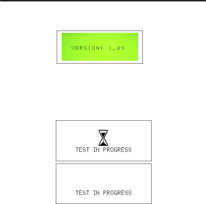
The system will run its start-up sequence and display the software version. An audible tone will sound during the initiation sequence.
Note: The entire power-up initiation sequence should not exceed ten seconds.
If the start-up sequence deviates from the description above, contact qualified service personnel following hospital protocol.
When the initiation sequence is complete, the system will go to Standby. If the system senses a generator, hand piece, or instrument fault during use, an audible alarm (tone with long pulses) will sound and a visual alarm indicator will appear on the control panel. (Refer to Chapter 9 – High-Level System Troubleshooting or the Troubleshooting Guide located on top of the generator unit to resolve the problem.)
|
GEN04 |
Go to www.e-ifu.com for the latest version of this manual. |
13 |

Service Manual
|
14 |
Go to www.e-ifu.com for the latest version of this manual. |
GEN04 |

Chapter 5 — Operation
Controls, Indicators, and Connections
|
Fig. 5-1 Front Panel |
||||
|
1 |
READY |
When this indicator is green, the system is ready for activation. |
||
|
Note: In the Ready mode, for self-diagnostic purposes, the system sends a |
||||
|
low-amplitude signal to the blade, causing the blade to vibrate slightly. This |
||||
|
vibration does not pose a risk to the user. |
||||
|
2 |
STANDBY |
Push this button to toggle between Standby and Ready modes. In Standby mode, |
||
|
this button, and the STANDBY icon, light up and all power is removed from the |
||||
|
hand piece. Both the foot switch and hand switch are disabled. Upon power-up, the |
||||
|
system defaults to Standby mode enabled. |
||||
|
3 |
INCREASE/ |
Push this button to increase or decrease the minimum (MIN) power |
||
|
DECREASE POWER |
setting to the desired level (from 1 to 5). The level chosen will be shown |
|||
|
LEVEL |
on the graphic display. The power level may be adjusted when the generator is in |
|||
|
Ready or Standby mode. |
||||
|
4 |
POWER |
This switch controls the main electrical power to the generator. |
||
|
5 |
VOLUME |
Turn this knob to adjust the volume of the activation tones. A tone will sound |
||
|
indicating the volume level selected. |
||||
|
6 |
MIN |
Indicates the user-settable MIN power level setting. When this power level is |
||
|
activated (by foot switch or hand switch), the MIN indicator will flash. On |
||||
|
power-up the system defaults to MIN power level 3. Refer to the instruments’ |
||||
|
package inserts for the recommended MIN power level. |
||||
|
7 |
MAX |
Indicates the maximum power level setting. This setting is always “5”. When this |
||
|
power level is activated (by foot switch or hand switch), the MAX indicator will |
||||
|
flash. |
||||
|
8 |
ALARM INDICATOR |
This red indicator appears only if a system alarm occurs in response to a |
||
|
component or generator problem. |
|
GEN04 |
Go to www.e-ifu.com for the latest version of this manual. |
15 |

Service Manual
|
9 |
HAND PIECE |
This receptacle is used to connect the hand piece to the generator. |
|
RECEPTACLE |
||
|
10 |
HAND ACTIVATION |
When the indicator is green, hand activation on the hand switching adaptor is |
|
enabled. To disable the Hand Activation mode, depress the button. Upon power-up, |
||
|
the system defaults to Hand Activation mode disabled. |
||
|
Note: If the foot switch is installed, the foot switch is always enabled. |
||
|
11 |
TEST |
Depressing this button initiates the Test mode. This mode is used during |
|
troubleshooting. The generator will emit a tone when the Test mode is active and |
||
|
“TEST IN PROGRESS” will appear on the display. |
||
|
12 |
GRAPHIC DISPLAY |
In Ready or Standby modes, this display indicates the minimum (user-settable level |
|
1 to 5) and maximum (level 5) power levels. If a system or component |
||
|
problem exists, error codes will appear on this display. |
16
 T3.15H 250V
Covered by one or more of the following US Patents
6,678,621
6,908,472
|
13 |
14 |
15 |
||
|
Fig. 5-2 Back Panel |
||||
|
13 |
FOOT SWITCH |
Identical receptacles allow connection of up to two foot switch |
||
|
RECEPTACLES |
assemblies for user convenience. If only one foot switch is used, connect to either |
|||
|
receptacle. |
||||
|
14 |
POTENTIAL |
This terminal provides a means for connection to a Potential Equalization |
||
|
EQUALIZATION |
Conductor. |
|||
|
TERMINAL |
||||
|
15 |
FUSES |
Refer to the Replacement Parts drawings in the back of this manual for additional |
||
|
fuse locations and fuse type. |
||||
|
16 |
POWER CORD |
This receptacle is used to attach the power cord to the generator. For |
||
|
RECEPTACLE |
power cord requirements, refer to Chapter 14 – System Specifications. |
|||
|
AUDIBLE SIGNALS |
The generator delivers audible tones to signal activation, test, and alarm states. The |
|||
|
user may choose from three activation tone pitches. Refer to |
||||
|
Chapter 15 – Adjustments for tone selection information. Upon power-up, the |
||||
|
system defaults to the last tone chosen (the mid-pitch tone is factory-set). |
|
16 |
Go to www.e-ifu.com for the latest version of this manual. |
GEN04 |
Chapter 5 — Operation
Screen Descriptions
Power-Up Screen
Below is an example of the Software Version displayed during power-up.
Fig. 5-3 Power-Up Screen
Tone Selection Screen
Refer to Chapter 15 – Adjustments for descriptions of the Tone Selection Screens.
User-Initiated and Pre-Activation Test Screens
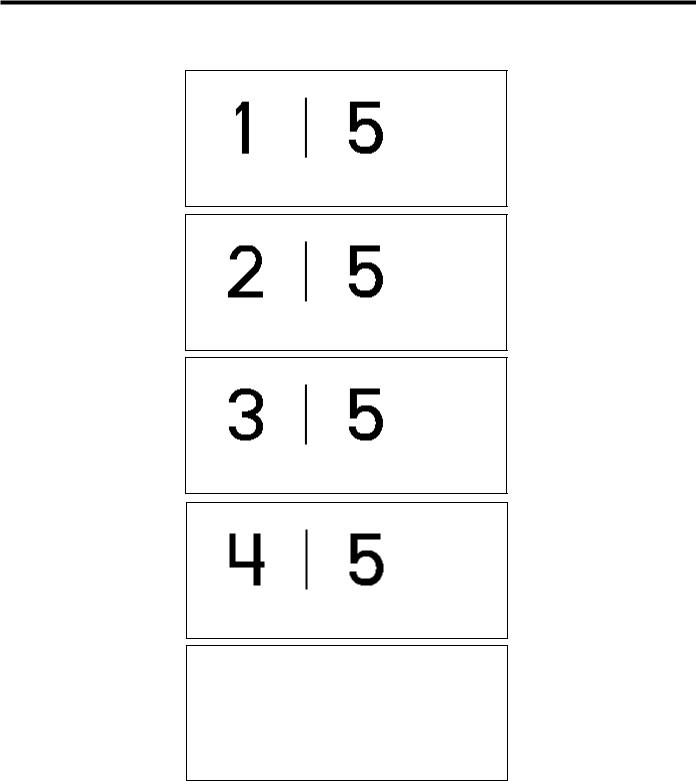
The generator will cycle between the following two screens, displaying each screen briefly, for the duration of the time that the system is in the User-Initiated Test state and Pre-Activation Test state. Refer to
Chapter 7 – Safety and Function Testing for details.
Fig. 5-4 Test in Progress Screens
Standby, Ready and Run Screens
The Standby, Ready, and Run screen appearances depend on the mode in which the system is running. In Normal mode, the Standby, Ready, and Run screens are the same and indicate the MAX power level of 5 on the right, and the user selected MIN power level on the left (1 to 5). In Developer/Biomed mode, the Standby screen indicates the user selected MIN power level on the left, and a subset of system parameters on the right. In Developer/Biomed mode, the Ready screen displays the user selected MIN Power level on the left (1 to 5) and the system run time parameters on the right. Developer/Biomed Run screen is identical to the Developer/ Biomed Ready screen.
|
GEN04 |
Go to www.e-ifu.com for the latest version of this manual. |
17 |
Service Manual
The following are all possible screens for the Standby, Ready, and Run states in Normal mode. The number on the left indicates the power level for MIN activation (1 to 5), and the number on the right is the power level for MAX activation.
Fig. 5-5 Standby, Ready and Run Screens in Normal Mode
Error Screens
Refer to Chapter 9 – High-Level System Troubleshooting for examples of each of these screens.
|
18 |
Go to www.e-ifu.com for the latest version of this manual. |
GEN04 |
![]()
Chapter 5 — Operation
System Operation
For an understanding of system operation, refer to the Harmonic Generator 300 System User Manual for instructions and specifications for use of the Harmonic Generator 300 System, Foot Switch, and Cart. Refer to package inserts provided separately for information about the Hand Piece, Hand Switching Adaptor, Adaptors, Test Tip and Instruments prior to using the system. This manual is not a reference to surgical techniques.
After completing system setup, the system may be operated.
1Place the generator in Ready mode by depressing the STANDBY button.
Note: In the Ready mode, for self-diagnostic purposes, the system sends a low-amplitude signal to the blade, causing the blade to vibrate slightly. This vibration does not pose a risk to the user.
2System check and activation:
Each time the generator is activated after exiting Standby, hold the instrument in the air (if coagulating shears are used, open the clamp arm) and depress the MIN or MAX power level on the foot switch or hand switching adaptor. “TEST IN PROGRESS” will appear on the graphic display and a rapid two-tone pulse will sound while the test is occurring. During this five-second period, a system check is being performed.
•If the system is operating properly, the activation tone corresponding to the power level activated will be heard when the check is complete. Stop activation, position the instrument on tissue, and resume activation.
•If the system is not operating properly, an error code will appear (refer to Chapter 9 – High-Level
System Troubleshooting or the Troubleshooting Guide located on top of the generator unit).
Warning: To avoid user or patient injury, ensure that the instrument is clear of other instruments, drapes, the patient or other objects during the system check. Safety measures (in accordance with hospital protocol) taken in the presence of aerosols should be in effect during the system check.
Note: The foot switch or hand switch must be depressed until the system check is complete. If the switch is released prematurely, the check will reinitiate at the next activation.
Note: The HAND ACTIVATION button on the generator control panel must be illuminated for the hand switch to be active. To deactivate the hand switch, depress the HAND ACTIVATION button (if the HAND ACTIVATION button is not illuminated, hand switch will be inactive).
Note: If the hand switch will not turn off during operation, depress the button corresponding to the power level opposite that being activated to turn it off — an alarm will sound. Press the HAND ACTIVATION button to disable the hand switching adaptor. Place the generator in Standby, and replace the hand switch; or, continue using the foot switch after deactivating the hand switch.
3If the system senses a generator, hand piece, or instrument fault during use, an audible alarm (tone with long pulses) will sound and a visual alarm indicator will appear on the control panel. (Refer to Chapter 9 – High-Level System Troubleshooting or the Troubleshooting Guide on top of the generator unit to resolve the problem.)
Warning: Place the generator in Standby before removing or replacing an instrument, hand switching adaptor or hand piece or when the system is not in use.
|
GEN04 |
Go to www.e-ifu.com for the latest version of this manual. |
19 |

Service Manual
System Shutdown
1Turn the generator power switch off and remove power cord from outlet.
2Disconnect the hand piece, instrument, and adaptor or hand switching adaptor (if used) and process them as indicated in their respective package inserts.
3Clean the generator and cart and disinfect the foot switch(es) following hospital protocol. Refer to the Harmonic Generator 300 System User Manual for detailed Cleaning and Disinfection instructions.
4Store foot switch(es) on the cart shelves provided. Each shelf will hold one foot switch.
5Wrap foot switch cable(s) and the power cord on the cart’s back handle for storage.
|
20 |
Go to www.e-ifu.com for the latest version of this manual. |
GEN04 |

Chapter 6 — Cleaning and Disinfection
Generator and Cart Cleaning
Clean generator and cart following hospital protocol. Before cleaning, turn the generator main power off and unplug the power cord from the grounded electrical outlet.
Warning: Spilling or spraying fluids on or into the generator or immersing the generator may result in damage to the generator and risk of shock or fire hazard.
Refer to the Harmonic Generator 300 System User Manual for detailed Cleaning and Disinfection instructions.
Foot Switch Cleaning
The foot switch and cable should be cleaned after each use.
Refer to the Harmonic Generator 300 System User Manual for detailed Cleaning and Disinfection instructions.
Disinfection (Generator, Footswitch and Cart)
Surface disinfection of the Generator, Foot Switch and Cart should follow the cleaning process. Particular attention to the disinfectant manufacturer’s recommendations must be followed for equipment that is knowingly and/or visibly contaminated with blood or bodily fluid. The foot switch can be immersed in the disinfectant solution.
Note: Keep the footswitch cable connector that connects to the generator dry at all times.
Refer to the Harmonic Generator 300 System User Manual for detailed Cleaning and Disinfection instructions.
|
GEN04 |
Go to www.e-ifu.com for the latest version of this manual. |
21 |

Service Manual
|
22 |
Go to www.e-ifu.com for the latest version of this manual. |
GEN04 |

Chapter 7 — Safety and Function Testing
Test the hand piece, generator, and foot switch for safety and function according to hospital protocol. Refer to individual package inserts for safety and function testing for other multi-patient use components.
Safety Test
Generator: A qualified hospital technician should perform a leakage current test.
Foot Switch: Examine the foot pedals, cable connectors, and cable for cracks or other damage and replace if damaged.
Other Components: Examine the components by following the instructions in their individual package inserts.
Function Test
1Attach the hand piece to the generator as described in Chapter 4 – System Setup, then attach the test tip rather than an instrument.
2Verify that the orange STANDBY indicator is illuminated.
3Push the STANDBY button to leave Standby mode and enter Ready mode.
Note: In the Ready mode, for self-diagnostic purposes, the system sends a low-amplitude signal to the blade, causing the blade to vibrate slightly. This vibration does not pose a risk to the user.
4Verify that the green READY indicator is illuminated.
5Verify that MIN Power Level 3 and MAX Power Level 5 are displayed.
6Push the Increase and Decrease Power Level button up and down to confirm the MIN Power Level changes from 1 to 5.
7Turn the generator off. Wait five seconds, then turn the generator back on. Wait ten seconds, then confirm MIN Power Level 3 and MAX Power Level 5 are displayed. Confirm the generator is not being activated unexpectedly.
8Press the TEST button to perform a User-Initiated Test. The system will run a series of tests to ensure the generator and hand piece are in proper working condition.
9Place the generator in Ready mode by depressing the STANDBY button. Hold the hand piece so that the distal portion is in the air and step on the MAX foot switch pedal (before activation begins, a fivesecond system check will be performed – “TEST IN PROGRESS” will appear on the display). After the test is completed, verify that the MAX Power Level indicator on the control panel flashes and that the MAX activation tone is heard.
Warning: To avoid user injury, ensure that the test tip is clear of tissue, other instruments, or other objects before activating the system.
10Hold the hand piece so that the distal portion is in air and step on the MIN foot switch pedal. Verify that the MIN Power Level indicator on the control panel flashes and that the MIN activation tone is heard.
Warning: To avoid user injury, ensure that the test tip is clear of tissue, other instruments, or other objects before activating the system.
|
GEN04 |
Go to www.e-ifu.com for the latest version of this manual. |
23 |

Service Manual
|
24 |
Go to www.e-ifu.com for the latest version of this manual. |
GEN04 |
 Loading…
- About
- Blog
- Projects
- Help
-
Donate
Donate icon
An illustration of a heart shape - Contact
- Jobs
- Volunteer
- People
Bookreader Item Preview
texts
Ethicon UltraCision Harmonic Scalpel Service Manual
Ethicon UltraCision Harmonic Scalpel Service Manual
- Addeddate
- 2020-05-19 20:42:52
- Classification
- Surgical Equipment;Electrosurgical Generator;Ethicon Endo-Surgery;Ethicon Endo-Surgery Harmonic Generator 300 System
- Identifier
- manual_Ethicon_UltraCision_Harmonic_Scalpel_Service_Manual
- Identifier-ark
- ark:/13960/t2b941r86
- Ocr
- ABBYY FineReader 11.0 (Extended OCR)
- Ppi
- 300
- Scanner
- Internet Archive Python library 1.9.0
comment
Reviews
There are no reviews yet. Be the first one to
write a review.
SIMILAR ITEMS (based on metadata)
Table of Contents for Ethicon Endo-Surgery ULTRACISION HARMONIC SCALPEL Generator 300:
-
e. Record the “XDUCER CAPACITANCE” value. -Press the STANDBY button, if necessary, until it illuminates. -Use the increase/decrease arrow keys to get to “Page 2 of 21”. -Record the number opposite “XDUCER CAPACITANCE”. -Press the STANDBY button until the Standby light turns off. -Leave the hand piece plugged into the generator. Do not remove hand piece during ent
-
3 If the system senses a generator, hand piece, or instrument fault during use, an audible alarm (tone with long pulses) will sound and a visual alarm indicator will appear on the control panel. (Refer to Chapter 4 – Troubleshooting or the Troubleshooting Guide to resolve the problem.) Warning: Place the generator in Standby mode before removing or replacing an instrument, hand switching adaptor or hand piece or when the system is not in use. System Shutdown 1 Turn the generato
-
GEN04
-
The following are possible causes of an increase in hand piece temperature. To correct, complete the appropriate steps below and allow the hand piece to cool before resuming operation. 1 The hand piece is still warm from recent steam sterilization. Allow the hand piece to cool at room temperature for at least 45 minutes or soak it in room-temperature sterile water for 5 minutes before resuming operation. Note: The hand switching adaptor (HSA07) sh
-
Manufacturer Authorized Representative in the European Community User Manual 28 GEN04
-
User Manual 18 GEN04
-
GEN04 User Manual 12 Error Code 1: Generator Error Code 1 indicates either there is a functional problem with the generator or the front panel button(s) were activated during power-up sequence. Cycle the power OFF then ON. If error persists, power off system and contact service. Error Code 2: Generator Error Code 2 indicates that the generator is overheating. Te m p
-
GEN04 User Manual 6 Unpacking Instructions The ULTR ACISION HARMONIC SCALPEL Generator 300 System includes several components that are purchased separately. Upon receiving the ordered components, check for visible shipping damage. If damage is seen, contact your Ethicon Endo-Surgery representative. System components may include the following parts (for product codes, see Chapter 8 – System Specifications): Generator 300 – includes the generator, power cord, user manual, and s
-
The U LTRAC ISION HARMONIC SCALPEL System utilizes ultrasonic energy to enable hemostatic cutting and/or coagulation of soft tissue. The system consists of an ultrasonic generator, a foot switch, an optional hand- switching adaptor, a hand piece, and a variety of open and minimally invasive instruments. Important: The U LTRACISION HARMONIC SCALPEL Generator 300 System User Manual is designed to provide instructions for use of the ULTR ACISION HARMONIC SCALPEL Generator
-
Product Codes Required Components for System Operation: GEN04: Generator 300 HP054/HP055: Hand Piece (includes HST02 Test Tip and TLB01 Blade Wrench) 1 Instruments and Adaptors: Contact your Ethicon Endo-Surgery representative for information about instruments available for use with this system. Some instruments may require use of an adaptor. Optional Components: FSW01: Foot Switch 2 HSA07: Hand Switch 1,2 CRT01: Cart 1 Refer to separate product insert supplied with this com
-
System Operation Important: The ULTR ACISION HARMONIC SCALPEL Generator 300 System User Manual is designed to provide instructions for use of the ULT RACISION HARMONIC SCALPEL Generator 300, Foot Switch, and Cart (see Chapter 8 – System Specifications — for applicable product codes). This manual is not a reference to surgical techniques. Note: Refer to package inserts provided separately for information about the Hand Piece, Han
-
GEN04
Questions, Opinions and Exploitation Impressions:
You can ask a question, express your opinion or share our experience of Ethicon Endo-Surgery ULTRACISION HARMONIC SCALPEL Generator 300 device using right now.
1 934 336 ₽
Нашли этот товар дешевле?
Этот товар продается поштучно.
Доставка по России:
Отправка осуществляется ТК СДЭК. Доставку оплачивает покупатель при получении товара. При заказе на сумму более 20 000 ₽ доставка осуществляется бесплатно.
Сертификаты:
-
Описание
-
Характеристики
Описание
Принцип работы:
Электрическая энергия, исходящая из генератора, управляемого микропроцессорами, преобразуется в механические колебания системой пьезокерамических кристаллов, расположенных в лапаросонической рукоятке. Лезвие инструмента вибрирует в продольном направлении с частотой 55,5 кГц. Амплитуда продольных колебаний варьируется в пределах 50–100 мкм на 5 уровнях при помощи установки параметров на передней панели генератора. Инструменты и технология Гармоник применяется для рассечения мягких тканей при необходимости надежного гемостаза с минимальным латеральным термическим поражением. Диссекция происходит вследствие механического растяжения тканей выше пределов эластичности. Коагуляция тканей происходит вследствие ультразвуковых механических колебаний молекул белков с их последующей денатурацией. Инструменты и технология Гармоник могут использоваться как замена моно- и биполярных инструментов, лазера или традиционного скальпеля, а также в сочетании с ними.
Аппарат функционирует в двух режимах – биполярном и ультразвуковом. В ультразвуковом режиме аппарат функционирует без воздействия электротока на пациента, при помощи механических высокочастотных колебаний лезвия насадки с одновременной диссекцией тканей, коагуляцией сосудов до 5 мм в диаметре и кавитационным препарированием тканей. Частота колебаний лезвия в ультразвуковом режиме – 55,5 кГц. В ультразвуковом режиме имеется 5 уровней изменения амплитуды движения рабочей насадки, с функцией ее регулировки. В режиме биполярной диссекции-коагуляции генератор работает с воздействием электротока на ткани, позволяя пересекать и коагулировать ткани, а также лигировать сосуды диаметром до 7 мм включительно. Имеется система оценки импеданса тканей для автоматического завершения цикла коагуляции и минимизации термического повреждения тканей. Поддержка биполярной коагуляции с автоматическим и полностью ручным завершением цикла коагуляции. Генератор обладает функцией автоматического распознавания подключенных насадок для минимизации потерь времени на их настройку. Совместимость со следующими типами рабочих насадок (диаметром 5 и 10 мм): ультразвуковые лезвия и ножницы, а также насадки биполярной коагуляции как для открытых, так и эндоскопических операций. Возможность ручной и педальной активации насадок. Все насадки могут применяться у пациентов с кардиостимуляторами. Возможность работы насадок вблизи жизненно важных структур с минимальным латеральным повреждением тканей, с возможностью разреза тканей обратной стороной рабочих насадок. Совместимость с биполярными насадками с ограничением температурного повреждения тканей не более 100 градусов С и возможностью коагуляции сосудов диаметром до 7 мм с возможностью разреза тканей. Наличие системы самотестирования генератора, ультразвуковой рукояти и насадок. Возможность принудительного тестирования генератора. Возможность тестирования при помощи тестового ключа в каждом из режимов работы (ультразвуковой, биполярный). Возможность обновления внутреннего программного обеспечения генератора. Наличие USB-разъема для проведения обновления и обслуживания генератора. Индикация количеств активации ультразвуковых рукоятей. Наличие на передней панели цветного дисплея с функцией распознавания прикосновения. Наличие на передней панели генератора визуальной индикации с отображением уровней мощности и возможностью регулировки уровней мощности. Возможность настройки генератора через пользовательское меню. Визуальная индикация ошибок и способов их устранения. Звуковая индикация режимов работы и ошибок с возможностью регулировки уровня громкости. Пользовательский интерфейс русифицирован. Защита разъемов от некорректного подключения штекеров. Наличие системы предотвращения случайного выпадения штекеров рукоятей и насадок из гнезда генератора. Возможность подключения адаптеров для работы ультразвуковыми и биполярными насадками подходящими к генераторам GEN04 и RF60. Возможность комплектования генератора специальной мобильной тележкой-подставкой с местом для хранения принадлежностей. Совместимость с ножным двухпедальным приводом с маркировкой соответствующего педали режима, имеющим защиту от деформации силового провода. Противоскользящее покрытие нижней поверхности ножного педального привода.
Потребляемая мощность генератора 500 ВА, работа в сети переменного тока с напряжением 100-240 В, частота 50/60 Гц.
Выходная мощность 135 Вт в биполярном режиме, 35 Вт в ультразвуковом режиме.
Габариты генератора – 13,6х35,5х35,0 см.
Масса генератора – 5,9 кг.
Соответствие стандарту IEC 60601-2-2:2009 (Группа 1), отсутствие РЧ-наводок на окружающее электронное оборудование.
Защита корпуса G11 от проникновения – IP21. Генератор поставляется в коплекте с сетевым кабелем IEC 60320 C13 с прямым кабельным вводом без углов.
Гарантия на генератор 12 месяцев.
Наличие авторизованного сервисного центра на территории РФ.
Ключевые свойства:
• Две передовые технологии — Гармоник и Энсил — в одном генераторе. Обеспечена совместимость со всеми существующими инструментами
• Простота установки и использования аппарата. Большой сенсорный дисплей с русским интерфейсом для легкой навигации по меню и выбору настроек
• Интуитивность и информативность. Один универсальный разъем с автоматическим распознаванием подключенного инструмента и технологии
• Возможность обновления ПО через USB-порт. Обеспечит совместимость генератора со всеми инновационными инструментами Ethicon Energy
• Безупречный компактный дизайн позволяет G11 разместиться в любой, даже самой небольшой и заставленной оборудованием операционной
• Баланс диссекции и коагуляции представлен пятью уровнями регулировки амплитуды колебаний лезвия. Уровни 4 и 5 предназначены для быстрого разделения маловаскуляризированных тканей с их одновременной коагуляцией. Уровень 3 является оптимальным с точки зрения баланса диссекции/коагуляции, уровни 1 и 2 предпочтительны для более выраженной коагуляции (хорошо васкуляризированные ткани)
Характеристики
| Артикул: | GEN11 |
| Производитель: | Ethicon (Johnson & Johnson) |
| Кол-во в запечатанной фабричной упаковке: | 1 шт |
| Наименование от производителя (ENG): | Generator Gen11 |
| Наименование от производителя (РУС): | Генератор электрохирургический, ультразвуковой G11 |