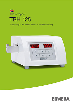
- Tablet Hardness Testers
Описание
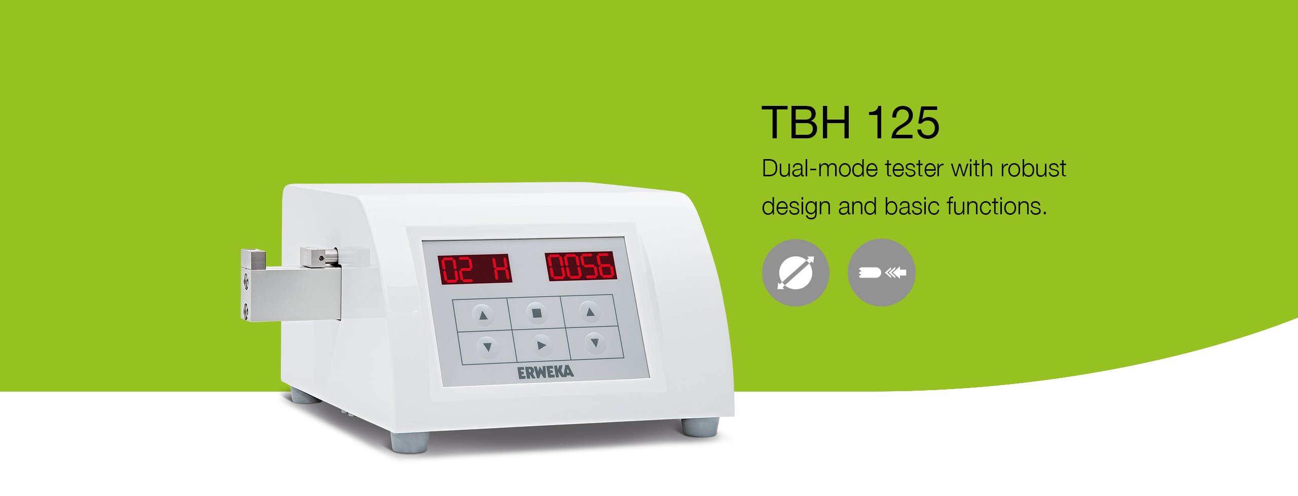
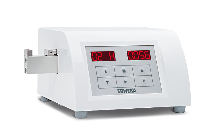
Тестер прочности TBH 125 – это базовое устройство тестирования прочности таблеток в линейке тестеров ERWEKA, которое гарантирует высокую точность результатов в сочетании с надежностью конструкции и простотой использования. Тестер работает в режимах “постоянная скорость” или “постоянное усилие” и управляется при помощи символьной клавиатуры, которая позволяет легко и просто вводить параметры тестирования.
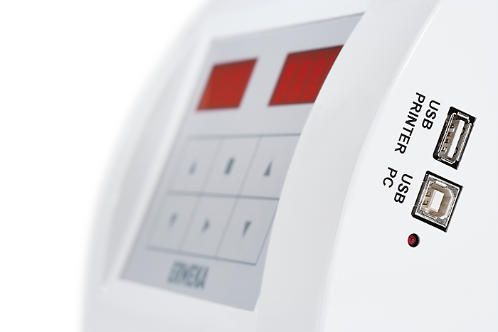
Тестер позволяет проводить измерение 3 физических величин (твердость, диаметр/длина и толщина). Результаты испытания, включая дату и время, отображаются на двух ярких LED дисплеях и могут быть распечатаны при помощи принтера, который подключается к интерфейсу USB. Станция измерения прочности в тестере TBH 125 может быть откалибрована при помощи специальных гирь или же автоматически при помощи системы AutoCal 2.0 (калибровка и проверка по трем точкам). В дополнение ко всему, устройство может генерировать протоколы с информацией о калибровке и всех сопутствующих данных (время и дата обслуживания, серийный номер).
Меню прибора позволяет проводить настройку режима измерения, по скорости или усилию, чувствительность измерения прочности и длительности паузы между измерениями для удаления остатков таблеток.
Основные преимущества
Маленькое устройство для простого и легкого использования и тестирования образцов на твердость.
![]()
Тестирование прочности
Диапазон измерения от 10 до 300 Ньютон
![]()
Измерение ширины
Образцы диаметром до 28 мм
![]()
USB интерфейсы
Интерфейс USB-A (принтер) для распечатки данных с указанием времени, даты, результатов и статистических данных; интерфейс USB-B для обновления ПО.
![]()
100 % соответствие USP/EP/JP/ ГФ XIII
Как и все продукты компании ERWEKA, тестеры прочности TBH 125 на 100 % соответствует требованиям фармакопей USP/EP/JP/ГФ XIII.
![]()
Различные единицы измерения
Единицы измерения усилия – Ньютон, Килопонд, или Strong Cobb
Галерея
Ниже приведены изображения, благодаря которым Вы сможете получить первое впечатление о тестере прочности ERWEKA TBH 125.
TBH 125
TBH 125
интерфейсы USB
TBH 125
процесс измерения
Скачать
Наши брошюры.
Instruction Manual
Tablet
Hardness Tester
TBH 125
ERWEKA GmbH · Ottostr. 20-22 · 63150 Heusenstamm · Germany · Tel: +49 (0) 6104 6903-0
Directors: Claudia Müller, Werner G. Müller · District court Offenbach HRB 2382
Fax: +49 (0) 6104 6903-40 · E-mail: [email protected] · www.erweka.com
Document version: 4.1
Date: 2017-03-07
Firmware version: from 1.45
Document No.: 21039
File name: TBH 125_Manual_21039_En_V4.1
Language: English
Number of pages: 36
Version table
Date
2012
2015-02-26
2015-09-18
2016-01-28
2016-02-22
2016-11-23
2017-03-07
Document version*
1.0
2.0
2.1
3.0
3.1
4.0
4.1
Amendment
AutoCal 2.0
Editorial revision
Firmware version increase; new Document No.
(old No.:690-309-0001), new format (11/15)
Editorial revision
TBH 125P cancelled
Editorial revision
* When the document version X.Y was changed, X means a technical change and Y – a document amendment only.
Copyright
The material in this document is the intellectual property of ERWEKA. Any copy or reproduction of this document or its parts without the written permission of and reference to ERWEKA is prohibited and will be prosecuted according to the law. All trademarks are the property of their respective owners.
Copyright © 2017 by ERWEKA
Instruction Manual
Tablet Hardness Tester
TBH 125
4
Table of Contents
TBH 125
1 – Introduction
1.1 – About this instruction manual
1.2 – Service
1.3 – Safety instructions and symbols
1.4 – Protection of the environment
2 – Safety
2.1 – Safety instructions
2.2 – Intended use
3 – Overview
3.1 – Description
3.2 – Device types
3.3 – Type label
3.4 – Construction
3.5 – Operation elements and connections
3.5.1 – Keypad and display
3.6 – Technical data
4 – Installation
4.1 – Storage and transport conditions
4.2 – Unpacking and checking
4.3 – Setup
4.3.1 – Positioning
4.3.2 – Acclimatization
12
12
4.3.3 – Required installation environment 12
4.4 – Device connecting and first switching on 13
12
12
12
12
10
11
9
9
8
8
8
8
7
7
7
5
6
5
5
6
5 – Configuration
5.1 – The SETT menu
5.2 – Pause
5.3 – Calibration position
5.4 – Hardness units
5.5 – Diameter and thickness units
5.6 – Hours
5.7 – Minutes
5.8 – Day
5.9 – Month
5.10 – Year
5.11 – Newton Factor
5.12 – Language
5.13 – Version
5.14 – Date format
5.15 – Method
5.16 – Terminology
5.17 – Automatic determination
5.18 – Printer
5.19 – Printer language
5.20 – Automatic measurement
5.21 – Data output
5.22 – Hardness
5.23 – Diameter
5.24 – Thickness
6 – Setting the Speed
7 – Setting the Force
17
17
18
18
17
17
17
17
16
16
16
16
15
15
16
16
19
19
20
20
20
18
18
19
19
20
21
8 – Switching the Printer on/off
9 – Calibration
9.1 – Diameter calibration
9.2 – Hardness calibration
9.2.1 – Static calibration
9.2.2 – Dynamic calibration
10 – Control
10.1 – Diameter
24
25
10.2 – Hardness 25
10.2.1 – Control of the static hardness calibration 25
10.2.2 – Control of the dynamic hardness calibration
26
11 – Performing the Measurements
12 – Results
27
28
13 – Statistics
14 – Maintenance
14.1 – Cleaning
14.2 – Inspection and maintenance
14.3 – Spare parts
Appendix
Example printouts of the protocols
21
22
22
23
23
24
28
29
29
29
29
31
31
21039 — 4.1
TBH 125 – Introduction 5
1 – Introduction
Thank you for purchasing the ERWEKA tablet hardness tester TBH 125 series!
1.1 – About this instruction manual
This instruction manual supports you in work with your ERWEKA device. It describes the device, its operation and gives you useful tips on its handling. Furthermore, read descriptions of installation and setting as well as detailed step-by-step work operations in the present manual. Pictures facilitate the understanding of processes described here.
The instruction manual is a part of the product. Read this manual completely and make sure you understand its content. Keep this manual in a safe place so that it will be available for any questions at a later date. This is important for warranty of permanent and accurate operation of the corresponding device.
The editorial team of ERWEKA appreciates your feedback regarding the present manual. Just send an e-mail to
[email protected]
with your topic and “technical documentation” as a subject. Your reply contributes to our high quality level.
1.2 – Service
Contact ERWEKA at
[email protected]
to receive the firmware updates, order the spare parts, in case of technical troubles or possible repairs. Please supply the following information:
• Type of the device (on the type label)
• Serial number of the device (on the type label)
• A short description of the case
21039 — 4.1
6
1.3 – Safety instructions and symbols
TBH 125 – Introduction
WARNING indicates a possible hazardous situation which, if not avoided, could result in death or serious injury.
CAUTION indicates a possible hazardous situation which, if not avoided, could result in moderate or minor injury.
HAZARD of electric shock! Indicates a possible hazardous situation which, if not avoided, can lead to injuries due to electric shock.
This symbol indicates a possible hazardous situation which, if not avoided, can lead to the equipment damage.
This symbol emphasizes the information to ensure smooth work process.
This symbol provides you with additional useful information.
1.4 – Protection of the environment
Note that residues of the test products must be properly disposed of in accordance with the applicable environmental regulations. According to the valid EC directives, all the electrical parts (electrical waste) must be disposed of appropriately.
21039 — 4.1
TBH 125 – Safety 7
2 – Safety
2.1 – Safety instructions
To guarantee the health and safety, read the following safety instructions before using the device.
WARNING
Wear the personal protective outfit and glasses, if necessary!
HAZARD of electric shock! Electric devices are to be plugged into safety sockets only. Use the delivered power cable. The voltage of the existing current supply is to be compared to the indications on the type label.
Before installation works always switch the corresponding device off and disconnect it from the rear panel.
ERWEKA devices should be operated by qualified and trained personnel only!
Pay attention to the on-site safety instructions for work in the laboratory and with the laboratory equipment!
2.2 – Intended use
The ERWEKA hardness tester type TBH 125 should be used only for performing hardness tests (optional diameter and thickness measurements), associated verification and quality control of tablets. The requirements for installation environment defined by ERWEKA shall be met.
ERWEKA devices should not be used for processing:
• products that are easily flammable or explosive
• products that develop vapours which may create flammable or explosive mixtures in combination with air
• products that release harmful or poisonous substances
The device should be operated and maintained only as it is foreseen and due to the instructions presented in this manual.
21039 — 4.1
8 TBH 125 – Overview
3 – Overview
3.1 – Description
The ERWEKA hardness tester type TBH 125 series is a compact device for the automatic measurement of hardness and optionally diameter and thickness of tablets and similar dosage forms.
The hardness test of tablets plays an important role in their formulation and production. The hardness test can be performed with the TBH 125 based on two different measurement principles (constant speed, constant force).
The device has been developed for customers who require robust design and easy handling. It is equipped with a membrane keypad and two LED-displays. During a test run up to 99 tablets can be tested.
The tablet hardness tester can be calibrated easely using the menu.
A printout of test reports from the device is possible through
a printer (opt.).
3.2 – Device types
Function
Hardness test
Diameter measurement
Thickness measurement
TBH 125
+
—
—
TBH 125 D
+
+
—
TBH 125 TD
+
+
+
3.3 – Type label
The type label is placed on the rear panel of the device and looks as follows:
Typ:
P
N
:
ERWEKA
R
GmbH
D-63150 Heusenstamm / Germany
VA I
N
: A
Serial No:
U : V xxxxxx.xxxx
F : Hz
Typ: Device type
Serial No: Serial number
I
P
N
: Normal output in volt-ampere [VA]
N
: Nominal current in ampere [A]
U: Voltage in volt [V]
F: Frequency in hertz [Hz]
21039 — 4.1
TBH 125 – Overview 9
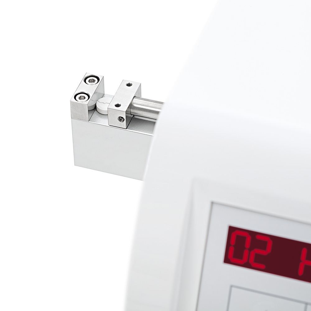
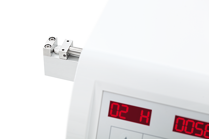
3.4 – Construction
2
1
3
1 Measurement station
2 Control panel
3 USB connections
3.5 – Operation elements and connections
A
B
D
F
Device front panel
E
C
Device rear panel
A Mains switch
B Measurement station
D
E
Power supply
USB connections
C Collection container (optional) F Keypad with two displays
21039 — 4.1
10
3.5.1 – Keypad and display
TBH 125 – Overview
Pict: Keypad with left and right LED display
Key symbol Description/Function
Arrow keys; to scroll the menus or submenus and select the values
The Stop/Exit key; to abort or stop a test as well as exit the current menu
The
Start/Enter key; to start a test and open a selected menu
All data inputs are confirmed with a beep tone.
21039 — 4.1
TBH 125 – Overview 11
3.6 – Technical data
TBH 125 series
Dimensions:
Height
Width
Depth
Weight:
160 mm
310 mm
300 mm
6 kg
Display/ keypad:
2 x 4 digit 16-segment LED display, touch foil keypad
Measuring principle:
Load cell with strain gauge, constant speed (0.50 – 3.00 mm/s) or constant force (10 – 200
N/s) with stepper motor, setting of automatic diameter measurement
Throughput:
1 – 99 samples per test, selectable
Hardness measurement station:
10 – 300 N (optional 10 – 500 N)
Accuracy: ± 1 N, Newton, Kilopond or Strong Cobb selectable
Diameter measurement station (optional):
2 – 28.00 mm
Accuracy: ± 0.05 mm, mm or inch selectable
Thickness measurement station (optional):
0.10 – 28.00 mm
Accuracy: ± 0.05 mm, mm or inch selectable
Power supply:
100 – 240 VAC ± 10 % / 50 – 60 Hz / 100 W
Safety:
Protection class: I / EN 61140
Protection type: IP 21 / IEC 529
Fuses:
115 V / 250 V, 2 x 3.15 A
Interfaces:
USB A for printer connection, USB B for updating via PC, optional RS 232 for data output
Printer:
Compatible printer available upon request
Calibration:
Completely menu guided, weights (static calibration)
Optional: AutoCal 2.0 (dynamic calibration)
Documentation:
Available through printer
21039 — 4.1
12 TBH 125 – Installation
4 – Installation
4.1 – Storage and transport conditions
The device should not be exposed to punches and vibrations.
Temperature and humidity should not be lower or higher than the values defined by ERWEKA (see
4.3.3 – Required installation environment
).
4.2 – Unpacking and checking
After receipt of the delivery, check the packaging and the device for transport damage. Check the tilt indicator label, if it is available, for undue turning of the packaging. At a gradient of 60° colored quartz sand flows into the display field and remains visible there.
If the undue transport or any damage is evident, take a photo of this and send it to our ERWEKA
1.2 – Service
immediately.
4.3 – Setup
4.3.1 – Positioning
Position the device on a horizontal, plane, stable surface, e.g. on a laboratory table, and pay attention not to displace it during operation.
For ease-of-use and accessibility, when positioning the device ensure that there is sufficient distance towards walls, cabinets or other fixed components of the facility.
Besides sticking to the requirements for installation environment defined by ERWEKA, avoid the following:
• Heat (heating, insolation)
• Direct draft through open windows, doors or air conditioning and ventilating systems
• Vibrations
• Dampness
4.3.2 – Acclimatization
If a cold device is moved to a warm environment, condensation may occur. Therefore you should allow the device to acclimatize for approximately two hours at room temperature, leaving it unplugged.
4.3.3 – Required installation environment
Ambient temperature in operation: +10°C up to +30°C
Storage and transport temperature:
Relative humidity:
-10°C up to +55°C
25-80% no condensation
Max. operating altitude (for balances): 3000 m above NN
21039 — 4.1
TBH 125 – Installation 13
4.4 – Device connecting and first switching on
Connect the device (connection on the device’s rear panel) with a safety socket. For this purpose use the delivered power cable.
HAZARD of electric shock! Electric devices are to be plugged into safety sockets only.
The voltage of the existing power supply has to meet the requirements of the type label!
ERWEKA accepts no liability in case of wrong connection.
Defective devices are to be opened by the authorized staff only.
In case of using an external printer, connect it to the USB A interface of the device.
Switching on
For switching on set the main switch on the device rear panel to the I position (on).
After successful device initialization the splash screen is shown.
Zeroing
The device must be zeroed after each switching on.
The splash screen is shown.
Press the Start/Enter key to start the procedure of zeroing.
“ZERO” is shown.
CAUTION
Squashing! While zeroing the test jaw moves. Do not touch the test station.
21039 — 4.1
14 TBH 125 – Installation
To zero the device, press the Start/Enter key.
The jaw moves to the counter-jaw, takes the zero point and returns to its initial position.
After successful determination of the device’s zero point (automatic repetition of zeroing in case of error), the number of the last measurement is displayed, see example:
This display means also that
• the device is ready for operation
• the device can be calibrated
• the device can be configured as needed
Scroll the menus using the arrow keys on the left.
Menu
REST
STAT
SPED
FORC
PRIN
CALI
CONT
SETT
Function
Display of the test results.
Display of the evaluations or statistics.
Setting of the constant speed in mm/s.
Setting of the constant force in N/s.
Switching the printer on/off or repeating a printout.
Calibration of the hardness and diameter test stations
(depending on the device option, see calibration).
Control measurements for calibration.
Configuration of the device.
Switching off
For switching off set the mains switch to the 0 position (off).
More information on the configuration and test performance you will find in the following chapters of this instruction manual.
21039 — 4.1
TBH 125 – Configuration 15
5 – Configuration
5.1 – The SETT menu
This menu guides you through the device configuration. In the menu items you can set the corresponding parameters.
To enter the SETT menu:
1. Using the left arrow keys select SETT on the ready-for-operation device.
2. Press the Start/Enter key for at least 8 seconds.
Scroll through the configuration menu with the left arrow keys.
LANG
VERS
DATF
METH
TERM
AUTO
PRIN
PRLG
AUME
DOUT
HARD
DIAM
THIC
Menu item
PAUS
CPOS
UNIH
UNID
HOUR
MINU
DAY
MONT
YEAR
NFCT
Function
Pause
Calibration positions
Hardness units
Diameter and thickness units
Hours
Minutes
Day
Month
Year
Newton factor
Language
Version
Date format
Measurement method
Terminology
Automatic determination
Printer
Printer language
Automatic measurement
Data output
Hardness
Diameter
Thickness
Read the information on each menu item below.
21039 — 4.1
16 TBH 125 – Configuration
5.2 – Pause 5.5 – Diameter and thickness units
In the PAUS menu item the time between the measurement cycles is set. The operator needs a certain time between the measurements to clean the test station and restock it with a new sample.
In the UNID menu item set the measurement unit for diameter and thickness.
1. Using the left arrow keys select the UNID item in the
SETT menu.
1. Using the left arrow keys select the PAUS item in the
SETT menu.
2. Using the right arrow keys select the required pause time [s].
2. Using the right arrow keys select the required measurement unit.
You can select millimeter (MM) or inch (INCH).
Adjustment range of pause time: 0 — 10 seconds 3. Confirm your selection with Start/Enter.
3. Confirm your selection with Start/Enter.
5.6 – Hours
5.3 – Calibration position
In the CPOS menu item the calibration position is set.
ERWEKA recommends setting 0.
1. Using the left arrow keys select the HOUR item in the
SETT menu.
1. Using the left arrow keys select the CPOS item in the
SETT menu.
The HOUR menu item belongs to the time setting. Set the hours here.
2. Using the right arrow keys select the required calibration position.
2. Using the right arrow keys select the required value for hours.
3. Confirm your selection with Start/Enter.
3. Confirm your selection with Start/Enter.
5.7 – Minutes
5.4 – Hardness units
In the UNIH menu item set the measurement unit for hardness.
1. Using the left arrow keys select the MINU item in the
SETT menu.
1. Using the left arrow keys select the UNIH item in the
SETT menu.
The MINU menu item belongs to the time setting. Set the minutes here.
2. Using the right arrow keys select the required measurement unit.
You can select Newton (N), Strong Cobb (SC) or
Kilopond (KP).
3. Confirm your selection with Start/Enter.
2. Using the right arrow keys select the required value for minutes.
3. Confirm your selection with Start/Enter.
21039 — 4.1
TBH 125 – Configuration 17
5.8 – Day 5.11 – Newton Factor
The DAY menu item belongs to the date setting. Set the day here.
In the NFCT menu item you can read the Newton factor, but not change it!
1. Using the left arrow keys select the DAY item in the
SETT menu.
1. Using the left arrow keys select the NFCT item in the
SETT menu.
2. Using the right arrow keys select the required day.
2. Press Stop/Exit to return to the SETT menu.
3. Confirm your selection with Start/Enter.
5.9 – Month
The MONT menu item belongs to the date setting. Set the month here.
The Newton factor is an internal calibration factor for the load cell and electronics. This value is saved after each calibration in the device‘s memory.
1. Using the left arrow keys select the MONT item in the
SETT menu.
5.12 – Language
In the LANG menu item you can select German or English as a menu language.
1. Using the left arrow keys select the LANG item in the
SETT menu.
2. Using the right arrow keys select the required month.
3. Confirm your selection with Start/Enter.
5.10 – Year
2. Using the right arrow keys select the required language (GERM or ENGL).
The YEAR menu item belongs to the date setting. Set the year here.
3. Confirm your selection with Start/Enter.
1. Using the left arrow keys select the YEAR item in the
SETT menu.
5.13 – Version
In the VERS menu item you can read the firmware version number, but not change it!
2. Using the right arrow keys select the required year.
3. Confirm your selection with Start/Enter.
1. Using the left arrow keys select the VERS item in the
SETT menu.
2. Press Stop/Exit to return to the SETT menu.
21039 — 4.1
18 TBH 125 – Configuration
5.14 – Date format 5.16 – Terminology
In the DATF menu item you can select the European or
American date display format.
1. Using the left arrow keys select the
SETT menu.
DATF item in the
In the TERM menu item you can select between calibration/control and justification/calibration. The terminology change is shown in the corresponding device menus and protocols.
1. Using the left arrow keys select the TERM item in the
SETT menu.
2. Using the right arrow keys select the required date format.
(EURO = Day:Month:Year = DD/MM/YYYY or
2. Using the right arrow keys select the required terminology.
USA = Year:Month:Day =YYYY/MM/DD) 3. Confirm your selection with Start/Enter.
3. Confirm your selection with Start/Enter.
5.17 – Automatic determination
5.15 – Method
In the METH menu item you can set the measurement method for hardness.
When using the automatic determination function you do not need to enter the nominal thickness and diameter before the test because the device determines them automatically.
1. Using the left arrow keys select the METH item in the
SETT menu.
1. Using the left arrow keys select the AUTO item in the
SETT menu.
2. Using the right arrow keys select the required measurement method.
(SPED = constant speed or FORC = constant force)
3. Confirm your selection with Start/Enter.
2. Using the right arrow keys select the ON option to switch this function on.
3. Confirm your selection with Start/Enter.
21039 — 4.1
TBH 125 – Configuration 19
5.18 – Printer 5.20 – Automatic measurement
In this menu item select the printer type according to the used printer. Select between internal (built-in) and external (conventional, e.g. HP
®
LaserJet or portable, e.g. Martell) printer. The printed protocols differ (see
Appendix
).
In this menu item activate or deactivate the automatic measurement for each tablet.
This function is available for devices of
TBH 125 TD type only.
1. Using the left arrow keys select the PRIN item in the
SETT menu.
1. Using the left arrow keys select the AUME item in the
SETT menu.
2. Using the right arrow keys select the required printer type.
2. Using the right arrow keys select the ON option to activate this function.
3. Confirm your selection with Start/Enter.
3. Confirm your selection with Start/Enter.
When activating this function the pause in the PAUS submenu is set to 0 (see
5.2 – Pause
).
5.19 – Printer language
In this menu item select the printer language according to the used external printer. For a conventional printer
(e.g. HP
®
LaserJet) select PCL and for a portable printer
(e.g. Martel) select ASCII.
1. Using the left arrow keys select the
SETT menu.
PRLG item in the
5.21 – Data output
The data transfer from the device to a PC is optionally possible. In case of this option a RS 232 interface is available on the rear panel of the device.
In this menu item activate the RS 232 interface for data output.
2. Using the right arrow keys select the required printer language.
1. Using the left arrow keys select the DOUT item in the
SETT menu.
3. Confirm your selection with Start/Enter.
2. Using the right arrow keys select the ON option to activate this function.
3. Confirm your selection with Start/Enter.
For the data transfer the PC must be connected with the device through the
RS 232 interface on the rear panel of the device. If the RS 232 interface (option) is not available on the device, deactivate the
DOUT menu item.
21039 — 4.1
20 TBH 125 – Setting the Speed
5.22 – Hardness
Activate this function to enable the hardness measurement.
1. Using the left arrow keys select the HARD item in the
SETT menu.
3. Confirm your selection with Start/Enter.
Activate the function of automatic measurement in the AUTO submenu not to enter the nominal thickness during the measurement (see
5.17 – Automatic determination
).
2. Using the right arrow keys select the ON option to activate this function.
6 – Setting the Speed
3. Confirm your selection with Start/Enter.
In the SPED menu set the measurement speed of the movable jaw. The selected measurement speed is printed out in the test protocol.
5.23 – Diameter
Activate this function to enable the diameter measurement.
1. Using the left arrow keys select the DIAM item in the
SETT menu.
Adjustment range: 0.05 — 3.00 mm/s
The default value is 2.3 mm/s.
Precondition for the use of this menu is the selection of the “constant speed” measurement method in the METH item
of the SETT menu (see
5.15 – Method
).
1. Using the left arrow keys select SPED on the ready-for-operation device.
2. Using the right arrow keys select the ON option to activate this function.
3. Confirm your selection with Start/Enter.
Activate the function of automatic measurement in the AUTO submenu not to enter the nominal diameter during the measurement (see
5.17 – Automatic determination
).
2. Using the right arrow keys select the required speed.
3. Confirm your selection with Start/Enter.
5.24 – Thickness
Activate this function to enable the thickness measurement.
1. Using the left arrow keys select the THIC item in the
SETT menu.
Comparability of the product break results is only ensured when using the same settings of the speed!
2. Using the right arrow keys select the ON option to activate this function.
21039 — 4.1
TBH 125 – Setting the Force 21
7 – Setting the Force 8 – Switching the Printer on/off
In the FORC menu set the force of the hardness measurement. The selected force is printed out in the test protocol.
In PRIN menu switch the connected printer for printing the test protocols on/off.
Adjustment range: 10 — 300 N/s
1. Using the left arrow keys select PRIN on the ready-for-operation device.
The default value is 20 N/s.
Precondition for the use of this menu is the selection of the “constant force” measurement method in the METH item of the SETT menu (see
5.15 – Method
).
1. Using the left arrow keys select FORC on the ready-for-operation device.
2. Using the right arrow keys select the ON option to activate the printer.
3. Confirm your selection with Start/Enter.
4. Press Start/Enter to repeat the last printout during the device operation.
2. Using the right arrow keys select the required force.
3. Confirm your selection with Start/Enter.
Comparability of the product break results is only ensured when using the same settings of the force!
21039 — 4.1
22 TBH 125 – Calibration
9 – Calibration
The device must be calibrated regularly. The user must define the interval for this.
The zeroing process is being performed. At that the jaw moves to the counter-jaw, takes the zero point and returns to its initial position.
In case of high or unexpected measurement deviations a calibration must be performed immediately, even if it is outside the interval!
4. Insert the 10 mm gauge block.
The CALI menu contains the DIAM and HARD items to calibrate the corresponding measurement stations.
5. Start the measurement with the Start/Enter key. The movable jaw moves to the gauge block and registers the second calibration point.
If a printer is connected and the PRIN menu is activated, on completion of a calibration cycle the calibration protocol is printed out automatically. The calibration protocol contains nominal and actual values, current control units and date.
Three different control measurements follow in succession to test the accuracy of the measurement station.
1. Using the left arrow keys select CALI on the ready-for-operation device and confirm your selection with Start/Enter.
6. Insert the 5 mm gauge block.
7. Press the Start/Enter key. The measured value is shown on the display.
8. Insert the 10 mm gauge block.
9. Press the Start/Enter key. The measured value is shown on the display.
2. Using the right arrow keys select the diameter ( DIAM) or hardness ( HARD) to calibrate the corresponding measurement station.
10. Insert the 15 mm gauge block.
The calibration procedures are described in the following sections.
11. Press the Start/Enter key. The measured value is shown on the display.
9.1 – Diameter calibration
1. Select the DIAM item from the Calibration menu.
12. Press the Start/Enter key to return to the Calibration menu.
2. Clean the movable and fixed jaws with a dusting brush.
3. Press the Start/Enter key.
21039 — 4.1
TBH 125 – Calibration 23
9.2 – Hardness calibration
9.2.1 – Static calibration
The static hardness calibration is done by weighing a calibration weight (30 kg is recommended). Then control measurements follow.
1. Select the HARD item from the Calibration menu.
WARNING
Falling object! Insecure positioning can lead to damages. Be careful when placing the control weights so that they do not fall!
7. Carefully place the required weight (30 kg is recommended).
2. Press the Start/Enter key.
3. Mount the justification adapter onto the jaw.
8. Press Start/Enter to confirm the weight. The new calculated Newton factor will be shown during ca. 2 seconds.
The linearity of the load cell is verified with 3 different control weights now (CON1: 30 kg, CON2: 20 kg, CON3:
10 kg).
9. Place the 30 kg weight.
10. Press the Start/Enter key for the confirmation. The current value is shown on the display.
11. Place the 20 kg weight.
4. Place the device carefully onto the side so that the justification adapter would be at the top.
12. Press the Start/Enter key for the confirmation. The current value is shown on the display.
Ensure that there is no LAN-cable in the port on the right side of the device!
5. Press the Start/Enter key.
13. Place the 10 kg weight.
14. Press the Start/Enter key for the confirmation. The current value is shown on the display.
The current weight, which acts upon the load cell, is shown (not exactly zero because of the justification adapter’s weight).
15. When the calibration is finished, remove the plate and place the device upright again.
6. Zero the weight by pressing the left arrow key.
16. Press the Start/Enter key to return to the Calibration menu.
21039 — 4.1
24 TBH 125 – Control
9.2.2 – Dynamic calibration
The dynamic hardness calibration is done with Erweka
AutoCal 2.0 Windows
®
XP.
12. Wait until the third control point (nominal value 100 N) is measured. The force measured by the load cell is displayed from the left and the force measured by the
AutoCal – from the right.
1. Plug the Erweka AutoCal 2.0 Windows
®
XP USB stick into the USB port.
2. Select the HARD item from the Calibration menu.
The deviation between the force measured by the load cell (device) and by the
AutoCal can differ in the range of max. ±
1 N! Otherwise you must repeat the calibration! For example:
3. Press the Start/Enter key.
106 N is the force measured by the load cell. 106.8 N is the force measured by the
AutoCal shown 10 times more precisely.
The deviation constitutes only 0.8 N.
4. Place the AutoCal control unit onto the measurement station.
10 – Control
5. Press the Start/Enter key.
In this menu the device calibration is checked. The control is done similar to the calibration.
6. Wait a few seconds. The force measured by the load cell is displayed from the left and the force measured by the AutoCal – from the right.
The CONT menu contains the DIAM and HARD items to control the calibration of the measurement stations.
The measurement range of the calibration and control is ca. ± 10 N from the given nominal values.
1. Using the left arrow keys select CONT on the ready-for-operation device and confirm your selection with Start/Enter.
7. Press the Start/Enter key.
8. Wait until the first control point (nominal value 300 N) is measured. The force measured by the load cell is displayed from the left and the force measured by the
AutoCal – from the right.
2. Using the right arrow keys select between diameter
( DIAM) or hardness (HARD) to control the calibration of the corresponding measurement station.
9. Press the Start/Enter key.
10. Wait until the second control point (nominal value 200
N) is measured. The force measured by the load cell is displayed from the left and the force measured by the AutoCal – from the right.
The control procedures are described in the following sections.
11. Press the Start/Enter key.
21039 — 4.1
TBH 125 – Control 25
10.1 – Diameter
1. Select the DIAM item from the Control menu.
10.2 – Hardness
10.2.1 – Control of the static hardness calibration
The control of the static hardness calibration is done by weighing calibration weights.
2. Clean the movable and fixed jaws with a dusting brush.
1. Select the HARD item from the Control menu.
3. Press the Start/Enter key.
2. Press the Start/Enter key.
The zeroing process is being performed. At that the jaw moves to the counter-jaw, takes the zero point and returns to its initial position.
3. Mount the justification adapter onto the jaw.
Three different control measurements follow in succession to test the accuracy of the test station.
4. Insert the 5 mm gauge block.
5. Press the Start/Enter key. The measured value is shown on the display.
4. Place the device carefully onto the side so that the justification adapter would be at the top.
Ensure that there is no LAN-cable in the port on the right side of the device!
6. Insert the 10 mm gauge block.
7. Press the Start/Enter key. The measured value is shown on the display.
The hardness calibration is verified with 3 different control weights (CON1: 30 kg, CON2: 20 kg, CON3: 10 kg) in succession.
8. Insert the 15 mm gauge block.
9. Press the Start/Enter key. The measured value is shown on the display.
10. Press the Start/Enter key to return to the Control menu.
WARNING
Falling object! Insecure positioning can lead to damages. Be careful when placing the control weights so that they do not fall!
21039 — 4.1
26 TBH 125 – Control
5. Place the 30 kg weight.
5. Press the Start/Enter key.
6. Press Start/Enter for the confirmation. The current value is shown on the display.
6. Wait until the force on the first control point (nominal value 300 N) is measured. The force measured by the load cell is displayed from the left and the force measured by the AutoCal – from the right.
7. Place the 20 kg weight.
8. Press Start/Enter for the confirmation. The current value is shown on the display.
7. Press the Start/Enter key.
8. Wait until the force on the second control point (nominal value 200 N) is measured. The force measured by the load cell is displayed from the left and the force measured by the AutoCal – from the right.
9. Place the 10 kg weight.
10. Press Start/Enter for the confirmation. The current value is shown on the display.
9. Press the Start/Enter key.
11. When the control measurements are finished, remove the plate and place the device upright again.
12. Press Start/Enter for the confirmation. The jaw returns to the initial position.
10. Wait until the force on the third control point (nominal value 100 N) is measured. The force measured by the load cell is displayed from the left and the force measured by the AutoCal – from the right.
10.2.2 – Control of the dynamic hardness calibration
The control of the dynamic hardness calibration is done with Erweka AutoCal 2.0 Windows
®
XP.
1. Plug the Erweka AutoCal 2.0 Windows
®
XP USB stick into the USB port.
2. Select the HARD item from the Control menu.
The deviation between the force measured by the load cell (device) and by the
AutoCal can differ in the range of max. ±
1 N! Otherwise you must repeat the calibration! For example:
106 N is the force measured by the load cell. 106.8 N is the force measured by the
AutoCal shown 10 times more precisely.
The deviation constitutes only 0.8 N.
3. Press the Start/Enter key.
4. Place the AutoCal control unit onto the measurement station.
The measurement range of the calibration and control is ca. ± 10 N from the given nominal values.
21039 — 4.1
TBH 125 – Performing the Measurements 27
11 – Performing the Measurements
The NUMB menu is shown on the display of the switched on device (see
4.4 – Connecting the device and its first switching on
).
1. Specify the number of samples.
CAUTION
Danger of squashing! During the zeroing procedure and the measurement the jaw moves. Do not touch the test station!
6. Place a sample right against the fixed test jaw vertically and as centered as possible to measure its thickness.
7. Press the Start/Enter key. The thickness is being measured.
The tablet thickness will not be measured if this option in the Settings menu is disabled (see
5.24 – Thickness
).
You can enter up to 99 samples. The number of samles entered by you is fixed and applies to all measurements that will be performed after this step.
8. Place a sample right against the fixed test jaw horizontally as centered as possible to measure its hardness and diameter.
2. Confirm the specified number of samples with
Start/
Enter.
9. Press the Start/Enter key. The hardness and diameter are being measured.
Step 3 applies to TBH 125 TD devices only.
Hardness and diameter will not be measured if these options in the Settings menu
are disabled (see
5.22 – Hardness
and
5.23 – Diameter
).
3. Specify the approximate thickness of samples. You can enter values from 0.10 to 28.00 mm. Confirm your entry with Start/Enter.
Step 4 applies to TBH 125 D and TD devices only.
The dust produced in the test process and left on the test station can lead to false measurements. Therefore, it should be removed after each sample. Apply the delivered dusting brush for this purpose.
The number of measurement repetitions (steps 6 — 9) depends on the specified number of samples.
4. Specify the approximate diameter of samples. You can enter values from 2.00 to 28.00 mm. Confirm your entry with Start/Enter.
Start/Enter must not be pressed after each tablet if the function of automatic measurement in the
Settings menu is enabled (see
5.20 – Automatic measurement
).
Steps 3 and 4 are omitted when the function of automatic determination in the Settings menu is enabled (see
5.17 – Automatic determination
).
5. Press the Start/Enter key to zero the test station.
21039 — 4.1
28 TBH 125 – Results
12 – Results 13 – Statistics
In the REST menu you can view the listed measurement results of the last test.
In the STAT menu you can view the statistic evaluations of the current test.
The measurement results will be stored until the device is switched off or a new test is performed.
The statistic evaluations will be stored until the device is switched off or a new test is performed.
1. Using the left arrow keys select REST on the ready-for-operation device and confirm your selection with Start/Enter.
1. Using the left arrow keys select STAT on the ready-for-operation device and confirm your selection with Start/Enter.
2. Using the left arrow keys scroll the listed results.
2. Using the left arrow keys scroll the statistic values.
The table below represents the specific statistic values for hardness, thickness and diameter of the sample.
Values on the left side indicate the number of tablet and measurement parameter (H for hardness, T for thickness and D for diameter). The measurement results are displayed on the right side.
Designation Explanation
HMIN/TMIN/DMIN
Minimum value of measurement
HMAX/TMAX/DMAX Maximum value of measurement
HM M/TM M/DM M Difference between maximum and minimum value
HAVR/TAVR/DAVR
HSTA/TSTA/DSTA
HREL/TREL/DREL
Average value
Standard deviation
Relative standard deviation
For example, the measurement result for 01T (thickness of the first sample) is 3.93mm.
Interpretation of the first letters in designations:
• H = hardness (break resistance)
• T = thickness
• D = diameter
21039 — 4.1
TBH 125 – Maintenance 29
14 – Maintenance
14.1 – Cleaning
14.2 – Inspection and maintenance
To guarantee the failure-free operation, it is recommended to clean the device regularly. The device is to be cleaned after each test. The dust must be removed thoroughly.
Read the following instructions before you begin with the cleaning.
Ensure that the device is regularly inspected and each time is clean.
To ensure a long lifetime of your units and systems we recommend regular maintenance performed by our specialized staff.
1. Disconnect the mains supply and, if available, the printer.
HAZARD of electric shock when cleaning the electric devices! Disconnect the mains supply for cleaning the electric devices! Switch the device off and unplug it for cleaning! Clean the electric devices without liquids.
In longer standstills
If the device is not used for a long time, follow the instructions below:
Instructions for cleaning
• Switch the device off and unplug it.
• Dismount additional components.
• Clean the device thoroughly.
• Store the device, its components and manual under conditions defined for the installation environment.
2. Clean the surfaces of the measurement stations to remove the tablet debris.
Non-compliance with the instructions given above can lead to damages!
Note that product residues must be properly disposed of in accordance with the applicable environmental regulations.
14.3 – Spare parts
For thorough cleaning ERWEKA recommends to exhaust the surfaces or apply a soft brush.
Electronic and mechanical replacements are to be made by the ERWEKA personnel or approved by ERWEKA!
Inaccurate measurement results!
Shaking and vibrations can displace the measuring devices. Clean the device carefully.
Pay attention that no particles collect in the guide rails, grooves and chinks.
Only original spare parts or components released by
ERWEKA should be used. Only repairs or changes on the device performed by the ERWEKA technicians or approved explicitly by ERWEKA are to be made.
3. Wipe the device with a soft and slightly damped cloth.
Do not use an excessively damped cloth but slightly damped one. Do not add any chemical cleansing agents to the cleaning water. For the lacquered housing parts use no cleansing agents which attack this material.
If needed, e.g. in case of serious dirtying, use a damp cloth and blot the cleaned surface dry.
21039 — 4.1
TBH 125 – Appendix 31
Appendix
Example printouts of the protocols
In this chapter you can find the examples of protocols printed from the device.
Calibration protocol
Check protocol
21039 — 4.1
TBH 125 – Appendix 33
Measurement protocol
In this example the measuring principle of constant speed (here: 2.3 mm/s) was used.
21039 — 4.1
Certifi cate of Compliance for
Konformitätserklärung für
Hardness Tester,
Type TBH 125
We, ERWEKA GmbH, declare under our sole responsibility that the product to which this declaration relates is in conformity with the following EU-Directives and harmonized standards:
■ Low Voltage Directive (LVD) 2014 / 35 / EU
■ Safety requirements for electrical equipment for measurement, control and laboratory use; EN 61010-1
■ Electromagnetic Compatibility, (EMC) Directive 2014 / 30 / EU
■ Electrical equipment for measurement, control and laboratory use; EN 61326-1
Wir, die ERWEKA GmbH, erklären in alleiniger Verantwortung, dass das Produkt, auf das sich diese Erklärung bezieht, mit folgenden EU-Richtlinien und harmonisierten Normen übereinstimmt:
■ Niederspannungsrichtlinie 2014 / 35 / EU
■ Sicherheitsbestimmungen für elektrische Mess-, Steuer-, Regel- und Laborgeräte; EN 61010-1
■ Elektromagnetische Verträglichkeit, EMV-Richtlinie 2014 / 30 / EU
■ Mess-, Steuer-, Regel- und Laborgeräte, EN 61326-1
Heusenstamm, 22.02.2016
Manfred Koller
-CTO-
ERWEKA GmbH · Ottostr. 20-22 · 63150 Heusenstamm · Germany · Tel: +49 6104 6903-0
Fax: +49 6104 6903-40 · E-mail: [email protected] · www.erweka.com
Managing Director & CEO: Werner G. Müller, Claudia Müller, Manfred Koller · District court Offenbach HRB 2382
ERWEKA GmbH · Ottostr. 20-22 · 63150 Heusenstamm · Germany · Tel: +49 (0) 6104 6903-0
Directors: Claudia Müller, Werner G. Müller · District court Offenbach HRB 2382
Fax: +49 (0) 6104 6903-40 · E-mail: [email protected] · www.erweka.com
Download Instruction manual of Erweka TBH 125 Analytical Instruments for Free or View it Online on All-Guides.com.

1

2

3

4

5

6

7

8

9

10

11

12

13

14

15

16

17

18

19

20

21

22

23

24

25

26

27

28

29

30

31

32

33

34

35

36

37

38

39

40

Instruction Manual
Tablet
Hardness Tester
ERWEKA GmbH · Ottostr. 20-22 · 63150 Heusenstamm · Germany · Tel: +49 (0) 6104 6903-0
Directors: Claudia Müller, Werner G. Müller · District court Offenbach HRB 2382
Fax: +49 (0) 6104 6903-40 · E-mail: [email protected] · www.erweka.com
Document version: 4.1
Date: 2017-03-07
Firmware version: from 1.45
Document No.: 21039
File name: TBH 125_Manual_21039_En_V4.1
Language: English
Number of pages: 36
Version table
Date
2012
2015-02-26
2015-09-18
2016-01-28
2016-02-22
2016-11-23
2017-03-07
Document version*
1.0
2.0
2.1
3.0
3.1
4.0
4.1
Amendment
AutoCal 2.0
Editorial revision
Firmware version increase; new Document No.
(old No.:690-309-0001), new format (11/15)
Editorial revision
TBH 125P cancelled
Editorial revision
* When the document version X.Y was changed, X means a technical change and Y – a document amendment only.
Copyright
The material in this document is the intellectual property of ERWEKA. Any copy or reproduction of this document or its parts without the written permission of and reference to ERWEKA is prohibited and will be prosecuted according to the law. All trademarks are the property of their respective owners.
Copyright © 2017 by ERWEKA
Instruction Manual
Tablet Hardness Tester
TBH 125
4
Table of Contents
TBH 125
1 – Introduction
1.1 – About this instruction manual
1.2 – Service
1.3 – Safety instructions and symbols
1.4 – Protection of the environment
2 – Safety
2.1 – Safety instructions
2.2 – Intended use
3 – Overview
3.1 – Description
3.2 – Device types
3.3 – Type label
3.4 – Construction
3.5 – Operation elements and connections
3.5.1 – Keypad and display
3.6 – Technical data
4 – Installation
4.1 – Storage and transport conditions
4.2 – Unpacking and checking
4.3 – Setup
4.3.1 – Positioning
4.3.2 – Acclimatization
12
12
4.3.3 – Required installation environment 12
4.4 – Device connecting and first switching on 13
12
12
12
12
10
11
9
9
8
8
8
8
7
7
7
5
6
5
5
6
5 – Configuration
5.1 – The SETT menu
5.2 – Pause
5.3 – Calibration position
5.4 – Hardness units
5.5 – Diameter and thickness units
5.6 – Hours
5.7 – Minutes
5.8 – Day
5.9 – Month
5.10 – Year
5.11 – Newton Factor
5.12 – Language
5.13 – Version
5.14 – Date format
5.15 – Method
5.16 – Terminology
5.17 – Automatic determination
5.18 – Printer
5.19 – Printer language
5.20 – Automatic measurement
5.21 – Data output
5.22 – Hardness
5.23 – Diameter
5.24 – Thickness
6 – Setting the Speed
7 – Setting the Force
17
17
18
18
17
17
17
17
16
16
16
16
15
15
16
16
19
19
20
20
20
18
18
19
19
20
21
8 – Switching the Printer on/off
9 – Calibration
9.1 – Diameter calibration
9.2 – Hardness calibration
9.2.1 – Static calibration
9.2.2 – Dynamic calibration
10 – Control
10.1 – Diameter
24
25
10.2 – Hardness 25
10.2.1 – Control of the static hardness calibration 25
10.2.2 – Control of the dynamic hardness calibration
26
11 – Performing the Measurements
12 – Results
27
28
13 – Statistics
14 – Maintenance
14.1 – Cleaning
14.2 – Inspection and maintenance
14.3 – Spare parts
Appendix
Example printouts of the protocols
21
22
22
23
23
24
28
29
29
29
29
31
31
21039 — 4.1
TBH 125 – Introduction 5
1 – Introduction
Thank you for purchasing the ERWEKA tablet hardness tester TBH 125 series!
1.1 – About this instruction manual
This instruction manual supports you in work with your ERWEKA device. It describes the device, its operation and gives you useful tips on its handling. Furthermore, read descriptions of installation and setting as well as detailed step-by-step work operations in the present manual. Pictures facilitate the understanding of processes described here.
The instruction manual is a part of the product. Read this manual completely and make sure you understand its content. Keep this manual in a safe place so that it will be available for any questions at a later date. This is important for warranty of permanent and accurate operation of the corresponding device.
The editorial team of ERWEKA appreciates your feedback regarding the present manual. Just send an e-mail to
[email protected]
with your topic and “technical documentation” as a subject. Your reply contributes to our high quality level.
1.2 – Service
Contact ERWEKA at
[email protected]
to receive the firmware updates, order the spare parts, in case of technical troubles or possible repairs. Please supply the following information:
• Type of the device (on the type label)
• Serial number of the device (on the type label)
• A short description of the case
21039 — 4.1
6
1.3 – Safety instructions and symbols
TBH 125 – Introduction
WARNING indicates a possible hazardous situation which, if not avoided, could result in death or serious injury.
CAUTION indicates a possible hazardous situation which, if not avoided, could result in moderate or minor injury.
HAZARD of electric shock! Indicates a possible hazardous situation which, if not avoided, can lead to injuries due to electric shock.
This symbol indicates a possible hazardous situation which, if not avoided, can lead to the equipment damage.
This symbol emphasizes the information to ensure smooth work process.
This symbol provides you with additional useful information.
1.4 – Protection of the environment
Note that residues of the test products must be properly disposed of in accordance with the applicable environmental regulations. According to the valid EC directives, all the electrical parts (electrical waste) must be disposed of appropriately.
21039 — 4.1
TBH 125 – Safety 7
2 – Safety
2.1 – Safety instructions
To guarantee the health and safety, read the following safety instructions before using the device.
WARNING
Wear the personal protective outfit and glasses, if necessary!
HAZARD of electric shock! Electric devices are to be plugged into safety sockets only. Use the delivered power cable. The voltage of the existing current supply is to be compared to the indications on the type label.
Before installation works always switch the corresponding device off and disconnect it from the rear panel.
ERWEKA devices should be operated by qualified and trained personnel only!
Pay attention to the on-site safety instructions for work in the laboratory and with the laboratory equipment!
2.2 – Intended use
The ERWEKA hardness tester type TBH 125 should be used only for performing hardness tests (optional diameter and thickness measurements), associated verification and quality control of tablets. The requirements for installation environment defined by ERWEKA shall be met.
ERWEKA devices should not be used for processing:
• products that are easily flammable or explosive
• products that develop vapours which may create flammable or explosive mixtures in combination with air
• products that release harmful or poisonous substances
The device should be operated and maintained only as it is foreseen and due to the instructions presented in this manual.
21039 — 4.1
8 TBH 125 – Overview
3 – Overview
3.1 – Description
The ERWEKA hardness tester type TBH 125 series is a compact device for the automatic measurement of hardness and optionally diameter and thickness of tablets and similar dosage forms.
The hardness test of tablets plays an important role in their formulation and production. The hardness test can be performed with the TBH 125 based on two different measurement principles (constant speed, constant force).
The device has been developed for customers who require robust design and easy handling. It is equipped with a membrane keypad and two LED-displays. During a test run up to 99 tablets can be tested.
The tablet hardness tester can be calibrated easely using the menu.
A printout of test reports from the device is possible through
a printer (opt.).
3.2 – Device types
Function
Hardness test
Diameter measurement
Thickness measurement
TBH 125
+
—
—
TBH 125 D
+
+
—
TBH 125 TD
+
+
+
3.3 – Type label
The type label is placed on the rear panel of the device and looks as follows:
Typ:
P
N
:
ERWEKA
R
GmbH
D-63150 Heusenstamm / Germany
VA I
N
: A
Serial No:
U : V xxxxxx.xxxx
F : Hz
Typ: Device type
Serial No: Serial number
I
P
N
: Normal output in volt-ampere [VA]
N
: Nominal current in ampere [A]
U: Voltage in volt [V]
F: Frequency in hertz [Hz]
21039 — 4.1
TBH 125 – Overview 9
3.4 – Construction
2
1
3
1 Measurement station
2 Control panel
3 USB connections
3.5 – Operation elements and connections
A
B
D
F
Device front panel
E
C
Device rear panel
A Mains switch
B Measurement station
D
E
Power supply
USB connections
C Collection container (optional) F Keypad with two displays
21039 — 4.1
10
3.5.1 – Keypad and display
TBH 125 – Overview
Pict: Keypad with left and right LED display
Key symbol Description/Function
Arrow keys; to scroll the menus or submenus and select the values
The Stop/Exit key; to abort or stop a test as well as exit the current menu
The
Start/Enter key; to start a test and open a selected menu
All data inputs are confirmed with a beep tone.
21039 — 4.1
TBH 125 – Overview 11
3.6 – Technical data
TBH 125 series
Dimensions:
Height
Width
Depth
Weight:
160 mm
310 mm
300 mm
6 kg
Display/ keypad:
2 x 4 digit 16-segment LED display, touch foil keypad
Measuring principle:
Load cell with strain gauge, constant speed (0.50 – 3.00 mm/s) or constant force (10 – 200
N/s) with stepper motor, setting of automatic diameter measurement
Throughput:
1 – 99 samples per test, selectable
Hardness measurement station:
10 – 300 N (optional 10 – 500 N)
Accuracy: ± 1 N, Newton, Kilopond or Strong Cobb selectable
Diameter measurement station (optional):
2 – 28.00 mm
Accuracy: ± 0.05 mm, mm or inch selectable
Thickness measurement station (optional):
0.10 – 28.00 mm
Accuracy: ± 0.05 mm, mm or inch selectable
Power supply:
100 – 240 VAC ± 10 % / 50 – 60 Hz / 100 W
Safety:
Protection class: I / EN 61140
Protection type: IP 21 / IEC 529
Fuses:
115 V / 250 V, 2 x 3.15 A
Interfaces:
USB A for printer connection, USB B for updating via PC, optional RS 232 for data output
Printer:
Compatible printer available upon request
Calibration:
Completely menu guided, weights (static calibration)
Optional: AutoCal 2.0 (dynamic calibration)
Documentation:
Available through printer
21039 — 4.1
12 TBH 125 – Installation
4 – Installation
4.1 – Storage and transport conditions
The device should not be exposed to punches and vibrations.
Temperature and humidity should not be lower or higher than the values defined by ERWEKA (see
4.3.3 – Required installation environment
).
4.2 – Unpacking and checking
After receipt of the delivery, check the packaging and the device for transport damage. Check the tilt indicator label, if it is available, for undue turning of the packaging. At a gradient of 60° colored quartz sand flows into the display field and remains visible there.
If the undue transport or any damage is evident, take a photo of this and send it to our ERWEKA
1.2 – Service
immediately.
4.3 – Setup
4.3.1 – Positioning
Position the device on a horizontal, plane, stable surface, e.g. on a laboratory table, and pay attention not to displace it during operation.
For ease-of-use and accessibility, when positioning the device ensure that there is sufficient distance towards walls, cabinets or other fixed components of the facility.
Besides sticking to the requirements for installation environment defined by ERWEKA, avoid the following:
• Heat (heating, insolation)
• Direct draft through open windows, doors or air conditioning and ventilating systems
• Vibrations
• Dampness
4.3.2 – Acclimatization
If a cold device is moved to a warm environment, condensation may occur. Therefore you should allow the device to acclimatize for approximately two hours at room temperature, leaving it unplugged.
4.3.3 – Required installation environment
Ambient temperature in operation: +10°C up to +30°C
Storage and transport temperature:
Relative humidity:
-10°C up to +55°C
25-80% no condensation
Max. operating altitude (for balances): 3000 m above NN
21039 — 4.1
TBH 125 – Installation 13
4.4 – Device connecting and first switching on
Connect the device (connection on the device’s rear panel) with a safety socket. For this purpose use the delivered power cable.
HAZARD of electric shock! Electric devices are to be plugged into safety sockets only.
The voltage of the existing power supply has to meet the requirements of the type label!
ERWEKA accepts no liability in case of wrong connection.
Defective devices are to be opened by the authorized staff only.
In case of using an external printer, connect it to the USB A interface of the device.
Switching on
For switching on set the main switch on the device rear panel to the I position (on).
After successful device initialization the splash screen is shown.
Zeroing
The device must be zeroed after each switching on.
The splash screen is shown.
Press the Start/Enter key to start the procedure of zeroing.
“ZERO” is shown.
CAUTION
Squashing! While zeroing the test jaw moves. Do not touch the test station.
21039 — 4.1
14 TBH 125 – Installation
To zero the device, press the Start/Enter key.
The jaw moves to the counter-jaw, takes the zero point and returns to its initial position.
After successful determination of the device’s zero point (automatic repetition of zeroing in case of error), the number of the last measurement is displayed, see example:
This display means also that
• the device is ready for operation
• the device can be calibrated
• the device can be configured as needed
Scroll the menus using the arrow keys on the left.
Menu
REST
STAT
SPED
FORC
PRIN
CALI
CONT
SETT
Function
Display of the test results.
Display of the evaluations or statistics.
Setting of the constant speed in mm/s.
Setting of the constant force in N/s.
Switching the printer on/off or repeating a printout.
Calibration of the hardness and diameter test stations
(depending on the device option, see calibration).
Control measurements for calibration.
Configuration of the device.
Switching off
For switching off set the mains switch to the 0 position (off).
More information on the configuration and test performance you will find in the following chapters of this instruction manual.
21039 — 4.1
TBH 125 – Configuration 15
5 – Configuration
5.1 – The SETT menu
This menu guides you through the device configuration. In the menu items you can set the corresponding parameters.
To enter the SETT menu:
1. Using the left arrow keys select SETT on the ready-for-operation device.
2. Press the Start/Enter key for at least 8 seconds.
Scroll through the configuration menu with the left arrow keys.
LANG
VERS
DATF
METH
TERM
AUTO
PRIN
PRLG
AUME
DOUT
HARD
DIAM
THIC
Menu item
PAUS
CPOS
UNIH
UNID
HOUR
MINU
DAY
MONT
YEAR
NFCT
Function
Pause
Calibration positions
Hardness units
Diameter and thickness units
Hours
Minutes
Day
Month
Year
Newton factor
Language
Version
Date format
Measurement method
Terminology
Automatic determination
Printer
Printer language
Automatic measurement
Data output
Hardness
Diameter
Thickness
Read the information on each menu item below.
21039 — 4.1
16 TBH 125 – Configuration
5.2 – Pause 5.5 – Diameter and thickness units
In the PAUS menu item the time between the measurement cycles is set. The operator needs a certain time between the measurements to clean the test station and restock it with a new sample.
In the UNID menu item set the measurement unit for diameter and thickness.
1. Using the left arrow keys select the UNID item in the
SETT menu.
1. Using the left arrow keys select the PAUS item in the
SETT menu.
2. Using the right arrow keys select the required pause time [s].
2. Using the right arrow keys select the required measurement unit.
You can select millimeter (MM) or inch (INCH).
Adjustment range of pause time: 0 — 10 seconds 3. Confirm your selection with Start/Enter.
3. Confirm your selection with Start/Enter.
5.6 – Hours
5.3 – Calibration position
In the CPOS menu item the calibration position is set.
ERWEKA recommends setting 0.
1. Using the left arrow keys select the HOUR item in the
SETT menu.
1. Using the left arrow keys select the CPOS item in the
SETT menu.
The HOUR menu item belongs to the time setting. Set the hours here.
2. Using the right arrow keys select the required calibration position.
2. Using the right arrow keys select the required value for hours.
3. Confirm your selection with Start/Enter.
3. Confirm your selection with Start/Enter.
5.7 – Minutes
5.4 – Hardness units
In the UNIH menu item set the measurement unit for hardness.
1. Using the left arrow keys select the MINU item in the
SETT menu.
1. Using the left arrow keys select the UNIH item in the
SETT menu.
The MINU menu item belongs to the time setting. Set the minutes here.
2. Using the right arrow keys select the required measurement unit.
You can select Newton (N), Strong Cobb (SC) or
Kilopond (KP).
3. Confirm your selection with Start/Enter.
2. Using the right arrow keys select the required value for minutes.
3. Confirm your selection with Start/Enter.
21039 — 4.1
TBH 125 – Configuration 17
5.8 – Day 5.11 – Newton Factor
The DAY menu item belongs to the date setting. Set the day here.
In the NFCT menu item you can read the Newton factor, but not change it!
1. Using the left arrow keys select the DAY item in the
SETT menu.
1. Using the left arrow keys select the NFCT item in the
SETT menu.
2. Using the right arrow keys select the required day.
2. Press Stop/Exit to return to the SETT menu.
3. Confirm your selection with Start/Enter.
5.9 – Month
The MONT menu item belongs to the date setting. Set the month here.
The Newton factor is an internal calibration factor for the load cell and electronics. This value is saved after each calibration in the device‘s memory.
1. Using the left arrow keys select the MONT item in the
SETT menu.
5.12 – Language
In the LANG menu item you can select German or English as a menu language.
1. Using the left arrow keys select the LANG item in the
SETT menu.
2. Using the right arrow keys select the required month.
3. Confirm your selection with Start/Enter.
5.10 – Year
2. Using the right arrow keys select the required language (GERM or ENGL).
The YEAR menu item belongs to the date setting. Set the year here.
3. Confirm your selection with Start/Enter.
1. Using the left arrow keys select the YEAR item in the
SETT menu.
5.13 – Version
In the VERS menu item you can read the firmware version number, but not change it!
2. Using the right arrow keys select the required year.
3. Confirm your selection with Start/Enter.
1. Using the left arrow keys select the VERS item in the
SETT menu.
2. Press Stop/Exit to return to the SETT menu.
21039 — 4.1
18 TBH 125 – Configuration
5.14 – Date format 5.16 – Terminology
In the DATF menu item you can select the European or
American date display format.
1. Using the left arrow keys select the
SETT menu.
DATF item in the
In the TERM menu item you can select between calibration/control and justification/calibration. The terminology change is shown in the corresponding device menus and protocols.
1. Using the left arrow keys select the TERM item in the
SETT menu.
2. Using the right arrow keys select the required date format.
(EURO = Day:Month:Year = DD/MM/YYYY or
2. Using the right arrow keys select the required terminology.
USA = Year:Month:Day =YYYY/MM/DD) 3. Confirm your selection with Start/Enter.
3. Confirm your selection with Start/Enter.
5.17 – Automatic determination
5.15 – Method
In the METH menu item you can set the measurement method for hardness.
When using the automatic determination function you do not need to enter the nominal thickness and diameter before the test because the device determines them automatically.
1. Using the left arrow keys select the METH item in the
SETT menu.
1. Using the left arrow keys select the AUTO item in the
SETT menu.
2. Using the right arrow keys select the required measurement method.
(SPED = constant speed or FORC = constant force)
3. Confirm your selection with Start/Enter.
2. Using the right arrow keys select the ON option to switch this function on.
3. Confirm your selection with Start/Enter.
21039 — 4.1
TBH 125 – Configuration 19
5.18 – Printer 5.20 – Automatic measurement
In this menu item select the printer type according to the used printer. Select between internal (built-in) and external (conventional, e.g. HP
®
LaserJet or portable, e.g. Martell) printer. The printed protocols differ (see
Appendix
).
In this menu item activate or deactivate the automatic measurement for each tablet.
This function is available for devices of
TBH 125 TD type only.
1. Using the left arrow keys select the PRIN item in the
SETT menu.
1. Using the left arrow keys select the AUME item in the
SETT menu.
2. Using the right arrow keys select the required printer type.
2. Using the right arrow keys select the ON option to activate this function.
3. Confirm your selection with Start/Enter.
3. Confirm your selection with Start/Enter.
When activating this function the pause in the PAUS submenu is set to 0 (see
5.2 – Pause
).
5.19 – Printer language
In this menu item select the printer language according to the used external printer. For a conventional printer
(e.g. HP
®
LaserJet) select PCL and for a portable printer
(e.g. Martel) select ASCII.
1. Using the left arrow keys select the
SETT menu.
PRLG item in the
5.21 – Data output
The data transfer from the device to a PC is optionally possible. In case of this option a RS 232 interface is available on the rear panel of the device.
In this menu item activate the RS 232 interface for data output.
2. Using the right arrow keys select the required printer language.
1. Using the left arrow keys select the DOUT item in the
SETT menu.
3. Confirm your selection with Start/Enter.
2. Using the right arrow keys select the ON option to activate this function.
3. Confirm your selection with Start/Enter.
For the data transfer the PC must be connected with the device through the
RS 232 interface on the rear panel of the device. If the RS 232 interface (option) is not available on the device, deactivate the
DOUT menu item.
21039 — 4.1
20 TBH 125 – Setting the Speed
5.22 – Hardness
Activate this function to enable the hardness measurement.
1. Using the left arrow keys select the HARD item in the
SETT menu.
3. Confirm your selection with Start/Enter.
Activate the function of automatic measurement in the AUTO submenu not to enter the nominal thickness during the measurement (see
5.17 – Automatic determination
).
2. Using the right arrow keys select the ON option to activate this function.
6 – Setting the Speed
3. Confirm your selection with Start/Enter.
In the SPED menu set the measurement speed of the movable jaw. The selected measurement speed is printed out in the test protocol.
5.23 – Diameter
Activate this function to enable the diameter measurement.
1. Using the left arrow keys select the DIAM item in the
SETT menu.
Adjustment range: 0.05 — 3.00 mm/s
The default value is 2.3 mm/s.
Precondition for the use of this menu is the selection of the “constant speed” measurement method in the METH item
of the SETT menu (see
5.15 – Method
).
1. Using the left arrow keys select SPED on the ready-for-operation device.
2. Using the right arrow keys select the ON option to activate this function.
3. Confirm your selection with Start/Enter.
Activate the function of automatic measurement in the AUTO submenu not to enter the nominal diameter during the measurement (see
5.17 – Automatic determination
).
2. Using the right arrow keys select the required speed.
3. Confirm your selection with Start/Enter.
5.24 – Thickness
Activate this function to enable the thickness measurement.
1. Using the left arrow keys select the THIC item in the
SETT menu.
Comparability of the product break results is only ensured when using the same settings of the speed!
2. Using the right arrow keys select the ON option to activate this function.
21039 — 4.1
TBH 125 – Setting the Force 21
7 – Setting the Force 8 – Switching the Printer on/off
In the FORC menu set the force of the hardness measurement. The selected force is printed out in the test protocol.
In PRIN menu switch the connected printer for printing the test protocols on/off.
Adjustment range: 10 — 300 N/s
1. Using the left arrow keys select PRIN on the ready-for-operation device.
The default value is 20 N/s.
Precondition for the use of this menu is the selection of the “constant force” measurement method in the METH item of the SETT menu (see
5.15 – Method
).
1. Using the left arrow keys select FORC on the ready-for-operation device.
2. Using the right arrow keys select the ON option to activate the printer.
3. Confirm your selection with Start/Enter.
4. Press Start/Enter to repeat the last printout during the device operation.
2. Using the right arrow keys select the required force.
3. Confirm your selection with Start/Enter.
Comparability of the product break results is only ensured when using the same settings of the force!
21039 — 4.1
22 TBH 125 – Calibration
9 – Calibration
The device must be calibrated regularly. The user must define the interval for this.
The zeroing process is being performed. At that the jaw moves to the counter-jaw, takes the zero point and returns to its initial position.
In case of high or unexpected measurement deviations a calibration must be performed immediately, even if it is outside the interval!
4. Insert the 10 mm gauge block.
The CALI menu contains the DIAM and HARD items to calibrate the corresponding measurement stations.
5. Start the measurement with the Start/Enter key. The movable jaw moves to the gauge block and registers the second calibration point.
If a printer is connected and the PRIN menu is activated, on completion of a calibration cycle the calibration protocol is printed out automatically. The calibration protocol contains nominal and actual values, current control units and date.
Three different control measurements follow in succession to test the accuracy of the measurement station.
1. Using the left arrow keys select CALI on the ready-for-operation device and confirm your selection with Start/Enter.
6. Insert the 5 mm gauge block.
7. Press the Start/Enter key. The measured value is shown on the display.
8. Insert the 10 mm gauge block.
9. Press the Start/Enter key. The measured value is shown on the display.
2. Using the right arrow keys select the diameter ( DIAM) or hardness ( HARD) to calibrate the corresponding measurement station.
10. Insert the 15 mm gauge block.
The calibration procedures are described in the following sections.
11. Press the Start/Enter key. The measured value is shown on the display.
9.1 – Diameter calibration
1. Select the DIAM item from the Calibration menu.
12. Press the Start/Enter key to return to the Calibration menu.
2. Clean the movable and fixed jaws with a dusting brush.
3. Press the Start/Enter key.
21039 — 4.1
TBH 125 – Calibration 23
9.2 – Hardness calibration
9.2.1 – Static calibration
The static hardness calibration is done by weighing a calibration weight (30 kg is recommended). Then control measurements follow.
1. Select the HARD item from the Calibration menu.
WARNING
Falling object! Insecure positioning can lead to damages. Be careful when placing the control weights so that they do not fall!
7. Carefully place the required weight (30 kg is recommended).
2. Press the Start/Enter key.
3. Mount the justification adapter onto the jaw.
8. Press Start/Enter to confirm the weight. The new calculated Newton factor will be shown during ca. 2 seconds.
The linearity of the load cell is verified with 3 different control weights now (CON1: 30 kg, CON2: 20 kg, CON3:
10 kg).
9. Place the 30 kg weight.
10. Press the Start/Enter key for the confirmation. The current value is shown on the display.
11. Place the 20 kg weight.
4. Place the device carefully onto the side so that the justification adapter would be at the top.
12. Press the Start/Enter key for the confirmation. The current value is shown on the display.
Ensure that there is no LAN-cable in the port on the right side of the device!
5. Press the Start/Enter key.
13. Place the 10 kg weight.
14. Press the Start/Enter key for the confirmation. The current value is shown on the display.
The current weight, which acts upon the load cell, is shown (not exactly zero because of the justification adapter’s weight).
15. When the calibration is finished, remove the plate and place the device upright again.
6. Zero the weight by pressing the left arrow key.
16. Press the Start/Enter key to return to the Calibration menu.
21039 — 4.1
24 TBH 125 – Control
9.2.2 – Dynamic calibration
The dynamic hardness calibration is done with Erweka
AutoCal 2.0 Windows
®
XP.
12. Wait until the third control point (nominal value 100 N) is measured. The force measured by the load cell is displayed from the left and the force measured by the
AutoCal – from the right.
1. Plug the Erweka AutoCal 2.0 Windows
®
XP USB stick into the USB port.
2. Select the HARD item from the Calibration menu.
The deviation between the force measured by the load cell (device) and by the
AutoCal can differ in the range of max. ±
1 N! Otherwise you must repeat the calibration! For example:
3. Press the Start/Enter key.
106 N is the force measured by the load cell. 106.8 N is the force measured by the
AutoCal shown 10 times more precisely.
The deviation constitutes only 0.8 N.
4. Place the AutoCal control unit onto the measurement station.
10 – Control
5. Press the Start/Enter key.
In this menu the device calibration is checked. The control is done similar to the calibration.
6. Wait a few seconds. The force measured by the load cell is displayed from the left and the force measured by the AutoCal – from the right.
The CONT menu contains the DIAM and HARD items to control the calibration of the measurement stations.
The measurement range of the calibration and control is ca. ± 10 N from the given nominal values.
1. Using the left arrow keys select CONT on the ready-for-operation device and confirm your selection with Start/Enter.
7. Press the Start/Enter key.
8. Wait until the first control point (nominal value 300 N) is measured. The force measured by the load cell is displayed from the left and the force measured by the
AutoCal – from the right.
2. Using the right arrow keys select between diameter
( DIAM) or hardness (HARD) to control the calibration of the corresponding measurement station.
9. Press the Start/Enter key.
10. Wait until the second control point (nominal value 200
N) is measured. The force measured by the load cell is displayed from the left and the force measured by the AutoCal – from the right.
The control procedures are described in the following sections.
11. Press the Start/Enter key.
21039 — 4.1
TBH 125 – Control 25
10.1 – Diameter
1. Select the DIAM item from the Control menu.
10.2 – Hardness
10.2.1 – Control of the static hardness calibration
The control of the static hardness calibration is done by weighing calibration weights.
2. Clean the movable and fixed jaws with a dusting brush.
1. Select the HARD item from the Control menu.
3. Press the Start/Enter key.
2. Press the Start/Enter key.
The zeroing process is being performed. At that the jaw moves to the counter-jaw, takes the zero point and returns to its initial position.
3. Mount the justification adapter onto the jaw.
Three different control measurements follow in succession to test the accuracy of the test station.
4. Insert the 5 mm gauge block.
5. Press the Start/Enter key. The measured value is shown on the display.
4. Place the device carefully onto the side so that the justification adapter would be at the top.
Ensure that there is no LAN-cable in the port on the right side of the device!
6. Insert the 10 mm gauge block.
7. Press the Start/Enter key. The measured value is shown on the display.
The hardness calibration is verified with 3 different control weights (CON1: 30 kg, CON2: 20 kg, CON3: 10 kg) in succession.
8. Insert the 15 mm gauge block.
9. Press the Start/Enter key. The measured value is shown on the display.
10. Press the Start/Enter key to return to the Control menu.
WARNING
Falling object! Insecure positioning can lead to damages. Be careful when placing the control weights so that they do not fall!
21039 — 4.1
26 TBH 125 – Control
5. Place the 30 kg weight.
5. Press the Start/Enter key.
6. Press Start/Enter for the confirmation. The current value is shown on the display.
6. Wait until the force on the first control point (nominal value 300 N) is measured. The force measured by the load cell is displayed from the left and the force measured by the AutoCal – from the right.
7. Place the 20 kg weight.
8. Press Start/Enter for the confirmation. The current value is shown on the display.
7. Press the Start/Enter key.
8. Wait until the force on the second control point (nominal value 200 N) is measured. The force measured by the load cell is displayed from the left and the force measured by the AutoCal – from the right.
9. Place the 10 kg weight.
10. Press Start/Enter for the confirmation. The current value is shown on the display.
9. Press the Start/Enter key.
11. When the control measurements are finished, remove the plate and place the device upright again.
12. Press Start/Enter for the confirmation. The jaw returns to the initial position.
10. Wait until the force on the third control point (nominal value 100 N) is measured. The force measured by the load cell is displayed from the left and the force measured by the AutoCal – from the right.
10.2.2 – Control of the dynamic hardness calibration
The control of the dynamic hardness calibration is done with Erweka AutoCal 2.0 Windows
®
XP.
1. Plug the Erweka AutoCal 2.0 Windows
®
XP USB stick into the USB port.
2. Select the HARD item from the Control menu.
The deviation between the force measured by the load cell (device) and by the
AutoCal can differ in the range of max. ±
1 N! Otherwise you must repeat the calibration! For example:
106 N is the force measured by the load cell. 106.8 N is the force measured by the
AutoCal shown 10 times more precisely.
The deviation constitutes only 0.8 N.
3. Press the Start/Enter key.
4. Place the AutoCal control unit onto the measurement station.
The measurement range of the calibration and control is ca. ± 10 N from the given nominal values.
21039 — 4.1
TBH 125 – Performing the Measurements 27
11 – Performing the Measurements
The NUMB menu is shown on the display of the switched on device (see
4.4 – Connecting the device and its first switching on
).
1. Specify the number of samples.
CAUTION
Danger of squashing! During the zeroing procedure and the measurement the jaw moves. Do not touch the test station!
6. Place a sample right against the fixed test jaw vertically and as centered as possible to measure its thickness.
7. Press the Start/Enter key. The thickness is being measured.
The tablet thickness will not be measured if this option in the Settings menu is disabled (see
5.24 – Thickness
).
You can enter up to 99 samples. The number of samles entered by you is fixed and applies to all measurements that will be performed after this step.
8. Place a sample right against the fixed test jaw horizontally as centered as possible to measure its hardness and diameter.
2. Confirm the specified number of samples with
Start/
Enter.
9. Press the Start/Enter key. The hardness and diameter are being measured.
Step 3 applies to TBH 125 TD devices only.
Hardness and diameter will not be measured if these options in the Settings menu
are disabled (see
5.22 – Hardness
and
5.23 – Diameter
).
3. Specify the approximate thickness of samples. You can enter values from 0.10 to 28.00 mm. Confirm your entry with Start/Enter.
Step 4 applies to TBH 125 D and TD devices only.
The dust produced in the test process and left on the test station can lead to false measurements. Therefore, it should be removed after each sample. Apply the delivered dusting brush for this purpose.
The number of measurement repetitions (steps 6 — 9) depends on the specified number of samples.
4. Specify the approximate diameter of samples. You can enter values from 2.00 to 28.00 mm. Confirm your entry with Start/Enter.
Start/Enter must not be pressed after each tablet if the function of automatic measurement in the
Settings menu is enabled (see
5.20 – Automatic measurement
).
Steps 3 and 4 are omitted when the function of automatic determination in the Settings menu is enabled (see
5.17 – Automatic determination
).
5. Press the Start/Enter key to zero the test station.
21039 — 4.1
28 TBH 125 – Results
12 – Results 13 – Statistics
In the REST menu you can view the listed measurement results of the last test.
In the STAT menu you can view the statistic evaluations of the current test.
The measurement results will be stored until the device is switched off or a new test is performed.
The statistic evaluations will be stored until the device is switched off or a new test is performed.
1. Using the left arrow keys select REST on the ready-for-operation device and confirm your selection with Start/Enter.
1. Using the left arrow keys select STAT on the ready-for-operation device and confirm your selection with Start/Enter.
2. Using the left arrow keys scroll the listed results.
2. Using the left arrow keys scroll the statistic values.
The table below represents the specific statistic values for hardness, thickness and diameter of the sample.
Values on the left side indicate the number of tablet and measurement parameter (H for hardness, T for thickness and D for diameter). The measurement results are displayed on the right side.
Designation Explanation
HMIN/TMIN/DMIN
Minimum value of measurement
HMAX/TMAX/DMAX Maximum value of measurement
HM M/TM M/DM M Difference between maximum and minimum value
HAVR/TAVR/DAVR
HSTA/TSTA/DSTA
HREL/TREL/DREL
Average value
Standard deviation
Relative standard deviation
For example, the measurement result for 01T (thickness of the first sample) is 3.93mm.
Interpretation of the first letters in designations:
• H = hardness (break resistance)
• T = thickness
• D = diameter
21039 — 4.1
TBH 125 – Maintenance 29
14 – Maintenance
14.1 – Cleaning
14.2 – Inspection and maintenance
To guarantee the failure-free operation, it is recommended to clean the device regularly. The device is to be cleaned after each test. The dust must be removed thoroughly.
Read the following instructions before you begin with the cleaning.
Ensure that the device is regularly inspected and each time is clean.
To ensure a long lifetime of your units and systems we recommend regular maintenance performed by our specialized staff.
1. Disconnect the mains supply and, if available, the printer.
HAZARD of electric shock when cleaning the electric devices! Disconnect the mains supply for cleaning the electric devices! Switch the device off and unplug it for cleaning! Clean the electric devices without liquids.
In longer standstills
If the device is not used for a long time, follow the instructions below:
Instructions for cleaning
• Switch the device off and unplug it.
• Dismount additional components.
• Clean the device thoroughly.
• Store the device, its components and manual under conditions defined for the installation environment.
2. Clean the surfaces of the measurement stations to remove the tablet debris.
Non-compliance with the instructions given above can lead to damages!
Note that product residues must be properly disposed of in accordance with the applicable environmental regulations.
14.3 – Spare parts
For thorough cleaning ERWEKA recommends to exhaust the surfaces or apply a soft brush.
Electronic and mechanical replacements are to be made by the ERWEKA personnel or approved by ERWEKA!
Inaccurate measurement results!
Shaking and vibrations can displace the measuring devices. Clean the device carefully.
Pay attention that no particles collect in the guide rails, grooves and chinks.
Only original spare parts or components released by
ERWEKA should be used. Only repairs or changes on the device performed by the ERWEKA technicians or approved explicitly by ERWEKA are to be made.
3. Wipe the device with a soft and slightly damped cloth.
Do not use an excessively damped cloth but slightly damped one. Do not add any chemical cleansing agents to the cleaning water. For the lacquered housing parts use no cleansing agents which attack this material.
If needed, e.g. in case of serious dirtying, use a damp cloth and blot the cleaned surface dry.
21039 — 4.1
TBH 125 – Appendix 31
Appendix
Example printouts of the protocols
In this chapter you can find the examples of protocols printed from the device.
Calibration protocol
Check protocol
21039 — 4.1
TBH 125 – Appendix 33
Measurement protocol
In this example the measuring principle of constant speed (here: 2.3 mm/s) was used.
21039 — 4.1
Certifi cate of Compliance for
Konformitätserklärung für
Hardness Tester,
Type TBH 125
We, ERWEKA GmbH, declare under our sole responsibility that the product to which this declaration relates is in conformity with the following EU-Directives and harmonized standards:
■ Low Voltage Directive (LVD) 2014 / 35 / EU
■ Safety requirements for electrical equipment for measurement, control and laboratory use; EN 61010-1
■ Electromagnetic Compatibility, (EMC) Directive 2014 / 30 / EU
■ Electrical equipment for measurement, control and laboratory use; EN 61326-1
Wir, die ERWEKA GmbH, erklären in alleiniger Verantwortung, dass das Produkt, auf das sich diese Erklärung bezieht, mit folgenden EU-Richtlinien und harmonisierten Normen übereinstimmt:
■ Niederspannungsrichtlinie 2014 / 35 / EU
■ Sicherheitsbestimmungen für elektrische Mess-, Steuer-, Regel- und Laborgeräte; EN 61010-1
■ Elektromagnetische Verträglichkeit, EMV-Richtlinie 2014 / 30 / EU
■ Mess-, Steuer-, Regel- und Laborgeräte, EN 61326-1
Heusenstamm, 22.02.2016
Manfred Koller
-CTO-
ERWEKA GmbH · Ottostr. 20-22 · 63150 Heusenstamm · Germany · Tel: +49 6104 6903-0
Fax: +49 6104 6903-40 · E-mail: [email protected] · www.erweka.com
Managing Director & CEO: Werner G. Müller, Claudia Müller, Manfred Koller · District court Offenbach HRB 2382
ERWEKA GmbH · Ottostr. 20-22 · 63150 Heusenstamm · Germany · Tel: +49 (0) 6104 6903-0
Directors: Claudia Müller, Werner G. Müller · District court Offenbach HRB 2382
Fax: +49 (0) 6104 6903-40 · E-mail: [email protected] · www.erweka.com
Назначение
Тестеры для определения линейных размеров, массы и прочности таблеток Erweka серий TBH, EasyCheck, MultiCheck (далее — тестеры) предназначены для измерений линейных размеров (толщина, диаметр/длина, ширина), массы и прочности (усилия излома) таблеток различных форм и покрытий.
Описание
Принцип работы тестеров заключается в измерении:
— линейных размеров таблеток с помощью линейного потенциометра тестера;
— массы таблеток с помощью весоизмерительной ячейки тестера;
— прочности (усилия излома) таблеток с помощью динамометрического датчика тестера. Динамометрический элемент оснащен тензометрическим датчиком, который преобразует
приложенную к датчику силу в изменение напряжения на вводах датчика. По этому изменению напряжения строится график, отражающий нарастание силы, приложенной к образцу. В момент разрушения образца кривая графика резко обрывается вниз ввиду отсутствия сопротивления со стороны образца. Пик полученной кривой соответствует значению твердости образца. Зависимость приложенной силы и показаний датчика в пределах измерения — линейная.
Конструктивно тестеры выполнены в виде настольного моноблока.
Примечание — У тестеров модификаций TBH 325 WTD и TBH 425 WTD весоизмерительная ячейка выполнена в виде внешнего блока.
Измерения прочности (усилия излома) таблеток производятся в режимах «Постоянное усилие» или «Постоянная скорость». Переключение этих режимов осуществляется через меню тестеров.
Для отображения результатов на внешних устройствах используются программы MC.NET и Win.Print. Вывод на печать осуществляется через USB порт.
Питание тестеров осуществляется от сети переменного тока.
Тестеры различных серий различаются между собой исполнением корпуса, способом эксплуатации, набором измеряемых параметров, диапазонами измерений, габаритными размерами и массой.
Тестеры серии TBH имеют 22 модификации: TBH 125, TBH 125 500N, TBH 125 D, TBH 125 D 500N, TBH 125 ТD, TBH 125 TD 500N, TBH 425, TBH 425 1000N, TBH 425 D, TBH 425 D 1000N, TBH 425 TD,TBH 425 TD 1000N, TBH 425 WTD, TBH 425 WTD 1000N, TBH 325, TBH 325 1000N, TBH 325 D, TBH 325 D 1000N, TBH 325 TD, TBH 325 TD 1000N, TBH 325 WTD, TBH 325 WTD 1000N.
TBH XXX XXX XXXN
Серия <-
Модификация: ^_
125 — измерение прочности (усилия излома), диаметра/длины и толщины;
325 — измерение массы, прочности (усилия излома), диаметра/длины и толщины.
Возможность создания базы данных;
425 — измерение массы, прочности (усилия излома), диаметра/длины и толщины.
Возможность создания базы данных, наличие магазина для автоматической подачи образцов
Измеряемый параметр: л-
D — диаметр/длина;
T — толщина;
W — масса.
Верхняя граница измерения прочности (усилия излома): <-
500N — 500 Н;
1000N — 1000 Н.
Примечания
1 Тестеры серии TBH, не имеющие в названии буквенных обозначений, используются только для измерения прочности (усилия излома);
2 Тестеры серии TBH, имеющие в названии букву W, позволяют проводить измерения массы с помощью внешней весоизмерительной ячейки;
3 Тестеры серии TBH, не имеющие в названии обозначения 500N/1000N, также служат для измерения прочности (усилия излома), но в более узком диапазоне.
Тестеры серии EasyCheck имеют 4 модификации: EasyCheck Basic, EasyCheck Basic 1000N, EasyCheck Pro, EasyCheck Pro 1000N.
Структура обозначения тестера серии EasyCheck:
EasyCheck XXX XXXN Серия м-1
Модификация: ^
Basic — измерение массы, прочности (усилия излома), диаметра/длины и толщины;
Pro — наличие встроенной позиционирующей консоли, предназначенной для автоматического позиционирования таблеток, что позволяет дополнительно измерять их ширину.
Верхняя граница измерения прочности (усилия излома): <-
1000N — 1000 Н.
Примечания
1 Тестеры серии EasyCheck, не имеющие в названии обозначения 1000N, также служат для измерения прочности (усилия излома), но в более узком диапазоне;
2 Измерение ширины производится линейным потенциометром, служащим для измерения диаметра/длины.
Тестеры серии MultiCheck имеют 6 модификаций: MultiCheck 5.1, MultiCheck 5.1 1000N, MultiCheck 6, MultiCheck 6 1000N, MultiCheck 6 Allrounder, MultiCheck 6 Allrounder 1000N.
Структура обозначения тестера серии MultiCheck:
MultiCheck XXX XXXN Серия м-1
Модификация: ^
5.1 — измерение массы, прочности (усилия излома), диаметра/длины и толщины.
Отсутствие дисплея — результаты выводятся в автономном ПО «MC.NET», устанавливаемом на управляющий компьютер и предназначенном для обработки, хранения и представления результатов измерений, а также управления работой тестеров;
6 — наличие дисплея и встроенного ПО для обработки, хранения и представления результатов измерений, а также управления работой тестеров.
Верхняя граница измерения прочности (усилия излома): <-
1000N — 1000 Н.
Примечания
1 Тестеры серии MultiCheck, не имеющие в названии обозначения 1000N, также служат для измерения прочности (усилия излома), но в более узком диапазоне.
2 Измерение ширины производится линейным потенциометром, служащим для измерения диаметра/длины.
3 Тестеры MultiCheck 6 Allrounder и MultiCheck 6 Allrounder 1000N имеют встроенную позиционирующую консоль, предназначенную для автоматического позиционирования таблеток, что позволяет дополнительно измерять их ширину.
Внешний вид тестеров и схема пломбировки от несанкционированного доступа представлены на рисунках 1-12.
v
Программное обеспечение
Тестеры (кроме модификации MultiCheck 5.1) имеют встроенное программное обеспечение (ПО), разработанное фирмой «ERWEKA GmbH». Тестеры модификации MultiCheck 5.1 имеют автономное ПО «MC.NET», разработанное фирмой «ERWEKA GmbH» на основе операционной системы Windows.
Автономное ПО устанавливается на управляющий компьютер тестера модификации MultiCheck 5.1 при первичном введении в эксплуатацию.
Основные функции встроенного и автономного ПО: управление процессом измерений, обработка сигналов с тензометрического датчика, хранение и представление результатов измерений.
Таблица 1 — Идентификационные данные встроенного ПО
|
Идентификационные данные (признаки) |
Значение для модификаций |
|||
|
TBH 125, TBH 125D, TBH 125ТD |
TBH 425, TBH 425D, TBH 425TD, TBH 425WTD, TBH 325, TBH 325D, TBH 325TD, TBH 325WTD |
MultiCheck 6, MultiCheck 6 1000N, MultiCheck 6 Allrounder, MultiCheck 6 Allrounder 1000N |
EasyCheck Basic, EasyCheck Basic 1000N, EasyCheck Pro, EasyCheck Pro 1000N |
|
|
Идентификационное наименование ПО |
Firmware |
Firmware |
Firmware |
Firmware |
|
Номер версии (идентификационный номер) ПО |
не ниже 2.0 |
не ниже 2.3 |
не ниже 1.1 |
не ниже 1.1 |
Таблица 2 — Идентификационные данные автономного ПО
|
Идентификационные данные (признаки) |
Значение |
|
Идентификационное наименование ПО |
MC.NET |
|
Номер версии (идентификационный номер) ПО |
не ниже 3.0 |
|
Цифровой идентификатор ПО (контрольная сумма исполняемого кода) |
3dfa27c76b18e040db1b433e2c7c7157 |
|
Алгоритм вычисления идентификатора ПО |
md5 |
Идентификационные данные встроенного ПО отображаются на дисплеях тестеров в статусном окне ПО.
Автономное ПО идентифицируется при подключении тестера к компьютеру. Идентификационные данные автономного ПО отображаются в главном окне программы при ее запуске.
Защита встроенного ПО от непреднамеренных и преднамеренных изменений соответствует уровню защиты «средний» по Р 50.2.077-2014.
Технические характеристики
Основные метрологические и технические характеристики тестеров приведены в таблицах 3 — 8. Потребляемая мощность тестеров не более 100 Вт.
Таблица 3 — Метрологические характеристики тестеров серии TBH
|
Наименование параметра |
Значение характеристики для модификаций тестера |
|||||
|
TBH 125 |
TBH 125 D |
TBH 125 ТD |
TBH 325/425 |
TBH 325 D/425 D |
TBH 325 TD/425 TD |
TBH 325 WTD/425 WTD |
|
Измеряемый параметр |
||||||
|
Диаметр/длина |
— |
+ |
— |
+ |
||
|
Толщина |
— |
+ |
— |
+ |
||
|
Масса |
— |
+ |
||||
|
Прочность (усилие излома) |
+ |
|
Наименование параметра |
Значение характеристики для модификаций тестера |
|||||
|
TBH 125 |
TBH 125 D |
TBH 125 ТD |
TBH 325/425 |
TBH 325 D/425 D |
TBH 325 TD/425 TD |
TBH 325 WTD/425 WTD |
|
Диапазон измерений |
||||||
|
Диаметр/длина, мм |
— |
от 2 до 28 |
— |
от 2 до 28 |
||
|
Толщина, мм |
— |
от 0,1 до 28,0 |
— |
от 0,1 до 10,0 (425TD) от 0,1 до 25,0 (325TD ) |
от 0,1 до 10,0 (425WTD) от 0,1 до 25,0 (325WTD ) |
|
|
Масса, г |
— |
от 0,02 до 64 |
||||
|
Прочность (усилие излома), Н |
от 10 до 300 |
от 10 до 500 |
||||
|
Пределы допускаемой абсолютной погрешности измерений |
||||||
|
Диаметр/длина, мм |
— |
±0,05 |
— |
±0,05 |
||
|
Толщина, мм |
— |
±0,05 |
— |
±0,05 |
||
|
Масса, г |
— |
±0,0001 |
||||
|
Прочность (усилие излома), Н |
±1 |
|||||
|
Примечание — Тестеры модификаций TBH 125 500N, TBH 125D 500N, 125TD 500N, TBH 325 1000N, TBH 325D 1000N, TBH 325TD 1000N, TBH 325WTD 1000N, TBH 425 1000N, TBH 425D 1000N, TBH 425TD 1000N, TBH425WTD 1000N соответствуют по своим метрологическим характеристикам аналогичным модификациям без обозначений 500N и 1000N во всем кроме диапазона измерений прочности (усилия излома). Диапазоны измерений прочности (усилия излома) для модификаций с обозначением 500N и 1000N от 10 до 500 Н и от 10 до 1000 Н, соответственно. |
Таблица 4 — Технические характеристики тестеров серии TBH
|
Модификация тестера |
Значение характеристики |
|||
|
Масса, кг, не более |
Г абаритные размеры (длина х ширина х высота), мм, не более |
Рабочие условия применения |
Параметры электрического питания от сети переменного тока |
|
|
TBH 125, TBH 125D, TBH 125ТD |
11 |
160x310x300 |
Температура окружающего воздуха от +15 до +35 °С Относительная влажность окружающего воздуха от 30 до 80 % Атмосферное давление от 84,0 до 106,7 кПа |
Напряжение (220±22)В Частота переменного тока (50±1) Гц |
|
TBH 425, TBH 425D, TBH 425TD, TBH 425WTD |
15 |
240x350x375 |
||
|
TBH 325, TBH 325D, TBH 325TD, TBH 325WTD |
10 |
310x350x375 |
||
|
Весоизмерительная ячейка Sartorius |
5,2 |
360x216x320 |
||
|
Весоизмерительная ячейка Mettler |
4,7 |
344x344x210 |
|
Наименование параметра |
Значение характеристики для модификаций тестера |
|||||
|
Multi ^eck 6 |
Mult^heck 61000H |
Multi ^eck 6 Allrounder |
Mult^heck 6 Allrounder 1000H |
Mult^heck 5.1 |
Multi ^eck 5.1 1000H |
|
|
Измеряемый параметр |
||||||
|
Диаметр/длина |
+ |
|||||
|
Толщина |
+ |
|||||
|
Масса |
+ |
|||||
|
Прочность (усилие излома) |
+ |
|||||
|
Ширина |
— |
+ |
— |
|||
|
Диапазон измерений |
||||||
|
Диаметр/длина, мм |
от 2 до 28 |
от 0,1 до 26,0 |
||||
|
Толщина, мм |
от 2 до 10 |
от 0,1 до 10,0 |
||||
|
Масса, г |
от 0,02 до 124,00 |
от 0,02 до 64,00 |
||||
|
Прочность (усилие излома), Н |
от 3 до 500 |
от 3 до 1000 |
от 3 до 500 |
от 3 до 1000 |
от 3 до 500 |
от 3 до 1000 |
|
Ширина, мм |
— |
от 2 до 28 |
— |
|||
|
Пределы допускаемой абсолютной погрешности измерений |
||||||
|
Диаметр/длина, мм |
0,05 |
±0,03 |
||||
|
Толщина, мм |
0,05 |
±0,03 |
||||
|
Масса, г |
±0,0001 |
±0,0003 |
||||
|
Прочность (усилие излома), Н |
±1 |
|||||
|
Ширина, мм |
— |
0,05 |
— |
Таблица 6 — Технические характеристики тестеров серии MultiCheck
|
Модификация тестера |
Значение характеристики |
|||
|
Масса, кг, не более |
Г абаритные размеры (длина х ширина х высота), мм, не более |
Рабочие условия применения |
Параметры электрического питания от сети переменного тока |
|
|
MultiCheck 5.1, MultiCheck 5.1 1000N |
55 |
610x610x630 |
Температура окружающего воздуха от +15 до +35 °С Относительная влажность окружающего воздуха от 30 до 80 % Атмосферное давление от 84,0 до 106,7 кПа |
Напряжение (220±22) В Частота переменного тока (50±1) Гц |
|
MultiCheck 6, MultiCheck 6 1000N, MultiCheck 6 Allrounder, MultiCheck 6 Allrounder 1000N |
50 |
613x643x630 |
|
Наименование параметра |
Значение характеристики для модификаций тестера |
|||
|
EasyCheck Basic |
EasyCheck Basic 1000H |
EasyCheck Pro |
EasyCheck Pro 1000H |
|
|
Измеряемый параметр |
||||
|
Диаметр/длина |
+ |
|||
|
Толщина |
+ |
|||
|
Масса |
+ |
|||
|
Прочность (усилие излома) |
+ |
|||
|
Ширина |
— |
+ |
||
|
Диапазон измерений |
||||
|
Диаметр/длина, мм |
от 2 до 26 |
|||
|
Толщина, мм |
от 2 до 10 |
|||
|
Масса, г |
от 0,02 до 64,00 |
|||
|
Прочность (усилие излома), Н |
от 3 до 500 |
от 3 до 1000 |
от 3 до 500 |
от 3 до 1000 |
|
Ширина, мм |
— |
от 2 до 26 |
||
|
Пределы допускаемой абсолютной погрешности измерений |
||||
|
Диаметр/длина, мм |
0,05 |
|||
|
Толщина, мм |
0,05 |
|||
|
Масса, г |
±0,0001 |
|||
|
Прочность (усилие излома), Н |
±1 |
|||
|
Ширина, мм |
— |
0,05 |
Таблица 8 — Технические характеристики тестеров серии EasyCheck
|
Модификация тестера |
Значение характеристики |
|||
|
Масса, кг, не более |
Г абаритные размеры (длина х ширина х высота), мм, не более |
Рабочие условия применения |
Параметры электрического питания от сети переменного тока |
|
|
EasyCheck Basic, EasyCheck Basic 1000N, EasyCheck Pro, EasyCheck Pro 1000N |
30 |
321x467x422 |
Температура окружающего воздуха от +15 до +35 °С Относительная влажность окружающего воздуха от 30 до 80 % Атмосферное давление от 84,0 до 106,7 кПа |
Напряжение (220±22) В Частота переменного тока (50±1) Гц |
Знак утверждения типа
наносится на передние панели тестеров в виде наклеек и на титульные листы руководств по эксплуатации методом компьютерной графики.
Комплектность
Комплект поставки тестеров приведен в таблицах 9 — 11.
|
Наименование |
Обозначение |
Количество |
Примечание |
|
Тестер |
TBH XXX XXX XXXN |
1 |
|
|
Сетевой кабель |
1 |
||
|
Комплект ЗИП |
1 |
||
|
Программное обеспечение |
Win.Print |
Поставляется по требованию заказчика |
|
|
Аналитические весы |
Mettler/Sartorius |
Для модификаций TBH 325/425 WTD Поставляется по требованию заказчика |
|
|
Измеритель толщины |
Для модификаций TBH 325/425 TD/WTD Поставляется по требованию заказчика |
||
|
Калибратор прочности AutoCal 2.0 |
AutoCal 2.0 |
Поставляется по требованию заказчика |
|
|
Паспорт |
Тестеры для определения линейных размеров, массы и прочности таблеток Erweka серии TBH. Паспорт |
1 |
|
|
Методика поверки |
МП-640-035-17 |
1 |
|
|
Руководство по эксплуатации |
Тестеры для определения линейных размеров, массы и прочности таблеток Erweka серий TBH, EasyCheck, MultiCheck. Руководство по эксплуатации |
1 |
|
Таблица 10 — Комплект поставки тестеров серии M |
ultiCheck |
||
|
Наименование |
Обозначение |
Количество |
Примечание |
|
Тестер |
MultiCheck XXX XXXN |
1 |
|
|
Сетевой кабель |
1 |
||
|
Комплект ЗИП |
1 |
||
|
Программное обеспечение MC.NET |
MC.NET |
1 (для модификаций MultiCheck 5.1, MultiCheck 5.1 1000N) |
Для остальных модификаций тестеров серии MultiCheck поставляется по требованию заказчика |
|
Калибратор прочности AutoCal 2.0 |
AutoCal 2.0 |
Поставляется по требованию заказчика |
|
|
Паспорт |
Тестеры для определения линейных размеров, массы и прочности таблеток Erweka серии MultiCheck. Паспорт |
1 |
|
Наименование |
Обозначение |
Количество |
Примечание |
|
Методика поверки |
МП-640-035-17 |
1 |
|
|
Руководство по эксплуатации |
Тестеры для определения линейных размеров, массы и прочности таблеток Erweka серий TBH, EasyCheck, MultiCheck. Руководство по эксплуатации |
1 |
Таблица 11 — Комплект поставки тестеров серии MultiCheck
|
Наименование |
Обозначение |
Количество |
Примечание |
|
Тестер |
MultiCheck XXX XXXN |
1 |
|
|
Сетевой кабель |
1 |
||
|
Комплект ЗИП |
1 |
||
|
Программное обеспечение MC.NET |
MC.NET |
Поставляется по требованию заказчика |
|
|
Калибратор прочности AutoCal 2.0 |
AutoCal 2.0 |
Поставляется по требованию заказчика |
|
|
Паспорт |
Тестеры для определения линейных размеров, массы и прочности таблеток Erweka серии EasyCheck. Паспорт |
1 |
|
|
Методика поверки |
МП-640-035-17 |
1 |
|
|
Руководство по эксплуатации |
Тестеры для определения линейных размеров, массы и прочности таблеток Erweka серий TBH, EasyCheck, MultiCheck. Руководство по эксплуатации |
1 |
Поверка
осуществляется по документу МП-640-035-17 «Инструкция. Тестеры таблеток Erweka серий TBH, EasyCheck, MultiCheck. Методика поверки», утвержденному ФГУП «ВНИИФТРИ»
30.08.2017 г.
Основные средства поверки:
— меры длины концевые плоскопараллельные 1-го разряда по ГОСТ Р 8.763-2011, диапазон значений длины от 1,25 до 100 мм;
— гири эталонные 1-го разряда по ГОСТ 8.021-2015, класс точности Е1 по ГОСТ OIML R 111-1-2009, масса от 1 мг до 100 г;
— динамометры 2-го разряда по ГОСТ 8.640-2014, основная погрешность ±0,06 %. Допускается применение аналогичных средств поверки, обеспечивающих определение
метрологических характеристик поверяемых тестеров с требуемой точностью.
Знак поверки наносится на свидетельство о поверке в виде наклейки или оттиска поверительного клейма.
Сведения о методах измерений
приведены в эксплуатационном документе.
Нормативные документы
ГОСТ 8.021-2015 ГСИ. Государственная поверочная схема для средств измерений массы ГОСТ Р 8.763-2011 ГСИ. Государственная поверочная схема для средств измерений длины от 110-9 до 50 м и длин волн в диапазоне от 0,2 до 50 мкм Техническая документация изготовителя.