- Manuals
- Brands
- Elstat Manuals
- Controller
- ems55advanced
- Manual
-
Contents
-
Table of Contents
-
Troubleshooting
-
Bookmarks
Quick Links
ems55advanced and
ems55Radvanced
18 February 2014
Firmware:U01 — n01 — ems55advanced and ems55Radvanced — GDC
Firmware: U02 — r01 — ems55advanced and ems55Radvanced — OFC
Elstat Electronics Ltd.
Astra Business Centre, Roman Way, Preston, Lancashire, PR2 5AP
+44 (0)161 2277200
www.elstatgroup.com
Related Manuals for Elstat ems55advanced
Summary of Contents for Elstat ems55advanced
-
Page 1
18 February 2014 Firmware:U01 — n01 — ems55advanced and ems55Radvanced — GDC Firmware: U02 — r01 — ems55advanced and ems55Radvanced — OFC Elstat Electronics Ltd. Astra Business Centre, Roman Way, Preston, Lancashire, PR2 5AP +44 (0)161 2277200… -
Page 2: Table Of Contents
2.2 Water ingress – advisory information for FMEA analysis 2.3 ems55 user interface 2.4 environmental ratings 2.5 ems55 series relay ratings 2.6 ems55advanced and ems55Radvanced wiring diagram 2.7 how to mount ems55 series controllers 2.8 how to mount ems55 series controllers 3 temperature input ranges 3.1 how to mount the appliance sensor…
-
Page 3
7.1 power-up sequence 7.2 display codes 7.3 how to access the menu (example) 7.4 how to view the ems55advanced parameter settings (PS) GDC firmware 7.5 how to view the ems55advanced parameter settings (PS) OFC firmware 7.6 how to run the test routine (tst) 7.7 how to perform a half reset (Hr) -
Page 4
10.17 differential (dIF) 10.18 display (dIS) 10.19 delay to saving (dS) 10.20 defrost termination temperature (dtd) 10.21 defrost termination method (dtF) 10.22 Maximum defrost on demand time (dtO) 10.23 freeze-up protection (dtt) ems55advanced and ems55Radvanced / General Use 4 of 84… -
Page 5
10.34 compressor rest time (rt) 10.35 saving differential (Sd) 10.36 motion sensor enable (Sn) 10.37 set point (SPC or SPF) 10.38 saving restart period (Sr) 10.39 saving set point (SSP) 11 technical data ems55advanced ems55advanced and ems55Radvanced / General Use 5 of 84… -
Page 6: Ems Controller Reference Guide
The purpose of this guide is to explain in detail all information regarding elstat controllers including the user interface, para- meters, accessories and troubleshooting. Complimentary information is also available from elstat such as accessory lists, accessory data sheets and single sheet user guides.
-
Page 7: What Is The Ems55Advanced
Unlike mechanical thermostats, the ems self-learning technology ensures the product is at the optimum serving tem- perature required by the customer from the moment the outlet opens. The ems55 series is available with an integrated motion sensor — ems55advanced, and with out and integrated motion sensor — ems55Radvanced…
-
Page 8: Ems55 Series Controllers
An appropriate level of protection must be given for the effects of water ingress due to condensation, product spillage, and so on. ems55 series controllers are designed for panel mounting and are secured using four self-tapping screws in the screw holes at each corner of the fascia. ems55advanced and ems55Radvanced / General Use 8 of 84…
-
Page 9: Water Ingress — Advisory Information For Fmea Analysis
Water ingress – advisory information for FMEA analysis Elstat products have been designed to minimise any risks associated with water ingress and all controllers are IPX5 certified. The OEM or installer is responsible to ensure that local/country laws and regulatory requirements are met.
-
Page 10: Environmental Ratings
C (131 minimum operating temperature C (32 housing material black polycarbonate ems55 series relay ratings The table below details the relay ratings of ems55advanced and ems55Radvanced controllers. maximum IEC rating maximum UL ratings relay @100-240VAC @ 120VAC compressor 10(10)A, p.f. 0.6…
-
Page 11: How To Mount Ems55 Series Controllers
Ingress protection (IP) rating of IPX5 applies to ems55 controllers mounted in the correction orientation only, as shown below. ems55advanced and ems55Radvanced / General Use 11 of 84…
-
Page 12: How To Mount Ems55 Series Controllers
Caution:The ems55 series controllers must not be exposed to temperatures greater than 55°C (131°F) or lower than 0°C (32°F). ems55 series controllers are designed for panel mounting and are secured using four countersunk self-tapping screws. The aperture and screw pitch dimensions are shown below. ems55advanced and ems55Radvanced / General Use 12 of 84…
-
Page 13: Temperature Input Ranges
C to 15 F to 59 evaporator sensor º º +/- 0.5 +/- 1 Note: The NTC (negative temperature coefficient) thermistor from elstat is rated at: º º º º C to 125 C (-31 F to 257 how to mount the appliance sensor The appliance sensor measures air temperature of the refrigerated compartment by measuring the return air temperature.
-
Page 14: How To Mount The Condenser Sensor
75% blocked. The temperature is then set as the value of the condenser high temperature (Ht) parameter. See «condenser high temperature (Ht)» on page 76 For example, fix using a metal pipe clip or direct fitting, as shown below. Elstat can supply pipe clips for 6-8mm and 8-10mm pipes. Caution: Do not use cable ties.
-
Page 15: How To Mount The Evaporator Sensor
Do not use cable ties. The head of the sensor is fragile and can be easily damaged. Using cable ties to secure the sensor head, or sensor cable, invalidates the warranty. ems55advanced and ems55Radvanced / General Use 15 of 84…
-
Page 16: Door Switch
Caution: Door switches and activators supplied by elstat must not be installed using rivets. Using rivets invalidates the warranty. The alignment of the door switch and activator is critical for the correct operation of the door switch. The following table details alignment tolerances.
-
Page 17: How To Mount The Enhanced Door Switch
Caution: Door switch kits supplied by elstat must not be installed using rivets. Using rivets invalidates the warranty. The alignment of the door switch and activator is critical for the correct operation of the door switch. The table below details the alignment tolerances.
-
Page 18: How To Mount Door Switches On Double-Door Coolers
The diagram below shows the horizontal, vertical, and gap alignment between the door switch and the activator for open and closed doors. For best results, elstat recommends that enhanced door switches are used with enhanced door switch activators. Per- formance will not be guaranteed if: enhanced activators are paired with current door switches enhanced door switches are paired with current activators.
-
Page 19: Ems Controllers Functionality
For example, people opening and closing the cooler door to retrieve products or movements detected in front of the cooler. ems controllers detect activity as follows: ems55advanced and ems55Radvanced / General Use 19 of 84…
-
Page 20: Ready Mode
The ems controller runs the compressor until the set point (S P) temperature is reached. The compressor is then stopped until the measured temperature reaches the set point (S P) plus differential (dI F) temperature. ems55advanced and ems55Radvanced / General Use 20 of 84…
-
Page 21: Saving Mode
The compressor runs until the saving set point (S S P) temperature is reached and then stops until the measured tem- perature reaches the saving set point (S S P) plus saving differential (S d) temperature. ems55advanced and ems55Radvanced / General Use 21 of 84…
-
Page 22: Defrost On Glass Door Coolers (Gdc)
Some ems controllers also enable defrost cycles to be started manually. The defrost cycle ends after the time defined by the defrost duration (dd) or on reaching the defrost termination tem- perature (dtd), as shown: ems55advanced and ems55Radvanced / General Use 22 of 84…
-
Page 23: Defrost On Open Front Coolers
2. started on the defrost activation temperature ( ) and terminated after the defrost duration ( ) – temperature-based. 3. started after the defrost interval ( ) and terminated on the defrost termination temperature ( ) – time-based. ems55advanced and ems55Radvanced / General Use 23 of 84…
-
Page 24: Freeze-Up Protection
The compressor rest time (rt) helps to avoid the following: passing peak current through the windings of the compressor motor switching off the refrigeration system on the thermal overload protection short-cycling the refrigeration system. ems55advanced and ems55Radvanced / General Use 24 of 84…
-
Page 25: Evaporator Fan Management
PF2 alarms may also indicate a problem with the gas cooler high temperature sensor when the cooler is a CO2 (R744) version. An ems55advanced CO2controller will alternate between PF2 and the gas cooler temperature sensor temperature.
-
Page 26: Lights Management
For alarm conditions, the ems controller displays the appropriate alarm code and, optionally, sounds an alarm buzzer. Buzzer enable (b0) defines whether to sound a warning buzzer for alarm conditions. ems55advanced and ems55Radvanced / General Use 26 of 84…
-
Page 27
For door open alarms, the buzzer sounds regardless of the buzzer enable ( ) setting. For more information about the parameters used in alarms: See «buzzer enable (b0)» on page 68 See «buzzer duration (b1)» on page 69 ems55advanced and ems55Radvanced / General Use 27 of 84… -
Page 28: Self-Learning
1 day (24 hours) 1 day automatic 3 days (72 hours) 7 days pre-set 7 days 7 days automatic 9 days For more information about the parameters used in self-learning: ems55advanced and ems55Radvanced / General Use 28 of 84…
-
Page 29: What Is The Self-Learning Matrix
At power-up, all the 30 minute periods are set to monitor (1) as shown in the following example matrix. For periods set to monitor (1), ems controllers run in the ready mode. ems55advanced and ems55Radvanced / General Use 29 of 84…
-
Page 30
The ems controller then continues to run in the ready mode for the remainder of the 7 day learning period whilst updating the self-learning matrix. At the end of the 7 day learning period, the ems controller has a complete self-learning matrix as shown in the following example matrix: ems55advanced and ems55Radvanced / General Use 30 of 84… -
Page 31: How A 1-Day Learning Period Works
Therefore, at the end of day 1, (first 24 hours), the ems controller has set all the 30 minutes to ready (2) or saving (0) depend- ing the outlet activity pattern as shown in the example matrix: ems55advanced and ems55Radvanced / General Use 31 of 84…
-
Page 32
Note that differences for activity patterns learnt on day 2 take two weeks to be implemented. Therefore, 1 day learning peri- ods are recommended only for outlets with regular patterns every day of the week. ems55advanced and ems55Radvanced / General Use 32 of 84… -
Page 33: How The Self-Learning Matrix Updates After The Learning Period
A key characteristic of an ems controller is the saving restart period. The saving restart period is time allocated for the cooler to lower the product temperature to the ready mode temperature ems55advanced and ems55Radvanced / General Use 33 of 84…
-
Page 34
30 minutes, and then switch to the saving mode (assuming no delay to saving dsparameter is in operation). For more information about the parameters used: See «delay to saving (dS)» on page 73 See «saving restart period (Sr)» on page 80 ems55advanced and ems55Radvanced / General Use 34 of 84… -
Page 35: User Guide
The cooler lights are off unless the light delay (L d) parameter keeps the lights on for a short period after the ems controller switches to the saving mode. The marketing mode (Ar) keeps the lights on for the duration of the saving mode. ems55advanced and ems55Radvanced / General Use 35 of 84…
-
Page 36: How To Access The Menu (Example)
(example) The password is a unique sequence of button operations. The password is supplied to OEMs, installers, and service engineers separately. step image Press and hold the set button ems55advanced and ems55Radvanced / General Use 36 of 84…
-
Page 37: How To View The Ems55Advanced Parameter Settings (Ps) Gdc Firmware
Press the down button twice (x2) Press the defrost / teach button twice (x2) how to view the ems55advanced parameter settings (PS) GDC firmware View the parameter settings to check the values of the parameters. View the parameter settings as follows: Press and hold the set button until PAS is displayed.
-
Page 38
See «delay to saving (dS)» on page 73 page 68 See «lights delay (Ld)» on page 77 See «saving restart period (Sr)» on page 80 See «refrigeration system failure (Ct) » on page 70 ems55advanced and ems55Radvanced / General Use 38 of 84… -
Page 39: How To View The Ems55Advanced Parameter Settings (Ps) Ofc Firmware
See «fan cycle on (FCO)» on page 75 See «fan cycle off (FCF)» on page 75 how to view the ems55advanced parameter settings (PS) OFC firmware View the parameter settings to check the values of the parameters. View the parameter settings as follows: Press and hold the set button until PAS is displayed.
-
Page 40: How To Run The Test Routine (Tst)
(tst) The test routine tests the following: all load relays analogue inputs (temperature sensors and door switch) motion sensor. Run the test routine as follows: ems55advanced and ems55Radvanced / General Use 40 of 84…
-
Page 41
To switch off the relays that are on, press the defrost button. 8. Press the defrost and set buttons simultaneously to test the analogue inputs. An A The display changes to ems55advanced and ems55Radvanced / General Use 41 of 84… -
Page 42: How To Perform A Half Reset (Hr)
Press and hold the set button until PAS is displayed. 2. Enter the button sequence of the menu entry password. 3. Ensure that is displayed. Press down to scroll down to the Hr menu. ems55advanced and ems55Radvanced / General Use 42 of 84…
-
Page 43: How To View The Last Three Alarms (Flt)
The alarms may have been cleared, or cancelled, by the retail outlet operators. how to view statistics To view the statistics, press the up and down buttons simultaneously. Statistics include door opening, average temperatures and activity counts. ems55advanced and ems55Radvanced / General Use 43 of 84…
-
Page 44
Average number of motion Total number of motion counts per day (24 hour period) motion counts counts since first powered during the past 7 days (7 x 24 up or last full reset ems55advanced and ems55Radvanced / General Use 44 of 84… -
Page 45
PE r para- meter. saving Possible values are: OFF or ON. No changes temperature disable OFF = Standby temperature dis- able is switched off. ON = Stanby temperature disable is switched on. ems55advanced and ems55Radvanced / General Use 45 of 84… -
Page 46: Troubleshooting
The option to display the temperature or the word US E is set by the display (dI S ) parameter. Follow the chart to ensure that the ems controller is working correctly in the ready mode for coolers with door switches fit- ted. ems55advanced and ems55Radvanced / General Use 46 of 84…
-
Page 47: How To Troubleshoot Condenser High Temperature (Ht) Alarms
Condenser high temperature (Ht) alert to problems with the refrigeration system such as a blocked condenser or faulty con- denser fan. Note: this alarm is not applicable with CO2 coolers and the ems55advanced CO2. For information about the condenser high temperature (Ht) parameter: See «condenser high temperature (Ht)»…
-
Page 48: How To Troubleshoot Door Alarms (Door Switch Fitted)
For information about the alarm delay (Ad) parameter: See «alarm delay (Ad)» on page 67 Follow the chart to troubleshoot door open alarms on coolers without a door switch fitted. ems55advanced and ems55Radvanced / General Use 48 of 84…
-
Page 49: How To Troubleshoot Motion Sensor Alarms
The ems controller stays in the ready mode if the motion detection LED is flashing continuously. For information about the motion sensor enable (S n ) parameter: See «motion sensor enable (Sn)» on page 79 Follow the chart to troubleshoot problems with the motion sensor. ems55advanced and ems55Radvanced / General Use 49 of 84…
-
Page 50: How To Troubleshoot Refrigeration System Failure (Rsf) Alarms
See «refrigeration system failure (Ct)» on page 70 See «set point (SPC or SPF)» on page 80 Follow the chart to troubleshoot refrigeration system failures. how to troubleshoot temperature sensor alarms ems controllers manage sensor failures as follows: ems55advanced and ems55Radvanced / General Use 50 of 84…
-
Page 51: How To Troubleshoot Problems With Freeze-Up Protection (888)
CO2 controllers continue to run the compressor normally and alternate the display and the gas cooler sensor temperature indicating a fault. alarms: ems controllers continue to run the compressor normally and alternate the display and the appliance sensor tem- perature.
-
Page 52: How To Troubleshoot Not Cooling Problems
See «freeze-up protection (dtt)» on page 74 how to troubleshoot not cooling problems Follow the chart below to troubleshoot problems of the cooler not cooling, i.e. the cooler or product is warm. ems55advanced and ems55Radvanced / General Use 52 of 84…
-
Page 53: Elstat Parameter Loader
The elstat parameter loader loads the parameter settings defined in XML files to the parameter programming tool (dongle). The parameter programming tool (dongle) connects to the parameter loader using a USB docking cradle and COM port on a host computer.
-
Page 54: What Are Checksums
The checksums displayed on the parameter loader are as follows: CRC-A Checksum of the XML file. For elstat reference purposes only. Checksum displayed on an ems55advanced with firmware version E52 F07. CRC-B Displayed when rebooting the ems controller following download of the parameter settings with the parameter programming tool (dongle).
-
Page 55: How To Install The Drivers On Windows Xp
Windows 7 and Windows Vista: Drivers install automatically by connecting the USB docking cradle For Windows XP, install the drivers as follows: Extract the ZIP file CDM20808.zip- from the files supplied by elstat which contain the Windows drivers for Windows XP — and save into a suitable location.
-
Page 56
Click Browse and select the folder where the drivers were saved. For example, C:Program Fileselstatdrivers. Click Next and wait while the wizard searches and downloads the drivers. Once completed, click Finish to close the wizard. ems55advanced and ems55Radvanced / General Use… -
Page 57: How To Install The Parameter Loader
Double-click the file Setup_ParameterLoader_Rx.x.exe to start in the setup wizard. Click Next to start the installation wizard. Select the destination location. Click Next to use the default location or click Browse to define a different location and then click Next. ems55advanced and ems55Radvanced / General Use 57 of 84…
-
Page 58
Select the Start menu folder. Click Next to use the default folder or click Browse to define a different folder and then click Next. Confirm that the setup information is correct. Click Install. ems55advanced and ems55Radvanced / General Use 58 of 84… -
Page 59: How To Start The Parameter Loader
Start the parameter loader as follows: Click Parameter Loader in the Start menu. Double-click the file ParameterLoader.exe located in, for example, the folder C:elstatParameterLoader. Note: On starting the parameter loader for the first time, the dialog box below appears prompting for the fractional sep- arator.
-
Page 60: How To Connect The Docking Cradle
Click the Start menu, select Control panel > System Device Manager > Ports (COM & LPT) as shown below. Check the COM port allocated to the USB docking cradle (USB Serial Port). For example, in the diagram above, COM3 has been allocated. ems55advanced and ems55Radvanced / General Use 60 of 84…
-
Page 61
Double-click the USB serial port and make a note of the port settings, as shown below. On the parameter loader, click the Edit Com port settings to display the dialog box below. ems55advanced and ems55Radvanced / General Use 61 of 84… -
Page 62: How To Load The Parameter Settings
To help service engineers, mark the appropriate checksum on the identification tag of the parameter programming tool (dongle). CRC-A Checksum of the XML file. For elstat reference purposes only. Checksum displayed on an ems55advanced with firmware version E52 F07. CRC-B Displayed when rebooting the ems controller following download of the para- meter settings with the parameter programming tool (dongle).
-
Page 63: How To View The Download Counter
Checksum displayed on an ems55advanced with firmware version E52 F07. CRC-C Displayed after manually scrolling through the parameter list, following down- load of the parameter settings with the parameter programming tool (dongle). Checksum displayed on all other ems controllers following download of the CRC-D parameter settings with the parameter programming tool (dongle).
-
Page 64: How To Configure The Parameter Loader
The table below shows the display when downloading parameters to the controller. display description The parameter programming tool (dongle) is connected. The parameter download is in progress. The parameters were download but are out of range. ems55advanced and ems55Radvanced / General Use 64 of 84…
-
Page 65
The parameters were not downloaded. The ems controller will reboot and display the checksum following successful parameter downloads. ems55advanced and ems55Radvanced / General Use 65 of 84… -
Page 66: Parameter Reference
The parameter values vary between different cooler types, cooler characteristics, operating environments, brand require- ments, and operational preferences. Parameter settings are defined by customers — OEMs, Bottlers and Brands — using an XML request form, and supplied in the relevant parameter information (PI) provided by elstat. 10.1 parameters by function The table below details the parameters grouped by function.
-
Page 67: Parameter By Owners
00 to 30 minutes global default 00 (disabled) 10.4 activity frequency (AF) The table below details the activity frequency (AF) parameter. ems55advanced and ems55Radvanced / General Use 67 of 84…
-
Page 68: Marketing Mode (Ar)
Sets the cooler lights to remain on at all times for display purposes. description The coolers lights will remain on during saving mode. Does not affect saving temperature. considerations Made available to ems55advanced GDC firmware from June 2012. Not used with OFC firmware. range 00 (off) or 01 (on) global default 00 (off) 10.6…
-
Page 69: Buzzer Duration (B1)
Applied to all temperatures measured on the appliance sensor. range -9.9 to 9.9°C (-18 to 18°F) global default 0.0°C (0°F) 10.9 calibration 2 (CA2) The table below details the calibration (C A2) parameter. ems55advanced and ems55Radvanced / General Use 69 of 84…
-
Page 70: Celsius Or Fahrenheit (Cf)
(rS F) alarm. considerations None range 00 to 100 hours global default 72 hours 10.12 display stability (d2) The table below details the display stability (d2) parameter. ems55advanced and ems55Radvanced / General Use 70 of 84…
-
Page 71: Defrost Duration (Dd)
Not available on GDC firmware. range -30 to 5ºC (-22 to 41ºF) -6ºC (21ºF) global default ems75sz: -15ºC (5ºF) 10.15 defrost interval (dE) The table below details the defrost interval (dE) parameter. ems55advanced and ems55Radvanced / General Use 71 of 84…
-
Page 72: Defrost Method (Df)
(rt). range 0.0 to 9.9°C (0 to 18°F) 4.0°C (7°F) global default ems75sz: 3.0°C (5°F) 10.18 display (dIS) The table below details the display (dI S) parameter. display ems55advanced and ems55Radvanced / General Use 72 of 84…
-
Page 73: Delay To Saving (Ds)
1 to 30ºC (33 to 86ºF) range ems75sz: -5 to 22ºC (23 to 71ºF) 9.0ºC (48ºF) global default ems75sz: 15.0ºC (59ºF) 10.21 defrost termination method (dtF) The table below details the defrost termination method (dtF) parameter. ems55advanced and ems55Radvanced / General Use 73 of 84…
-
Page 74: Maximum Defrost On Demand Time (Dto)
Defines the temperature to stop further cooling to prevent freeze-up due to low temperature. considerations Must be set below the set point (S P) temperature. range -15 to 10ºC (5 to 50ºF) 0.0ºC (32ºF) global default ems75sz: -6.0°C (21°F) ems55advanced and ems55Radvanced / General Use 74 of 84…
-
Page 75: Fan Cycle Off (Fcf)
Not related to fan cycle on (FC O) or fan cycle off (FC F). considerations Not used with OFC firmware or the ems25 range 01 to 30ºC (33 to 86ºF) global default 15ºC (59ºF) ems55advanced and ems55Radvanced / General Use 75 of 84…
-
Page 76: High Voltage (Hi)
The high voltage (HI) values are approximations and not actual voltage readings (see table below). 1. Must not be used with an external voltage stabiliser considerations 2. Must only be used with an elstat supplied transformer 3. Only used with ems55advancedand ems55Radvanced range…
-
Page 77: Uninterrupted Pull Down (Ipd)
Defines the minimum voltage allowed before switching off the compressor. description The low voltage (L O) values are approximations and not actual voltage readings (see table below). considerations 1. Must not be used with an external voltage stabiliser ems55advanced and ems55Radvanced / General Use 77 of 84…
-
Page 78: Learning Period (Lp)
2. Must only be used with an elstat supplied transformer 3. Only used with ems55advancedand ems55Radvanced range 90 to 160 (not Vac) global default 90 (disabled) 100V line 110-120V line 220-240V line voltage voltage voltage Note: Voltage measurement is accurate to ±10%. 203 Caution: Low voltage protection is not calibrated and actual performance can be influenced by several factors.
-
Page 79: Compressor Rest Time (Rt)
0.0 to 9.9°C (0 to 18°F) 4.0°C (7°F) global default ems75sz: 3.0°C (5°F) 10.36 motion sensor enable (Sn) The table below details the motion sensor enable (S n) parameter. display ems55advanced and ems55Radvanced / General Use 79 of 84…
-
Page 80: Set Point (Spc Or Spf)
0 to 240 minutes (in multiples of 30 minutes) global default 120 minutes 10.39 saving set point (SSP) The table below details the saving set point (S S P) parameter. ems55advanced and ems55Radvanced / General Use 80 of 84…
-
Page 81
Must be set above the set point (S P) plus differential (dI F) temperature. 0.0 to 9.9°C (32 to 50°F) range ems75sz: -9.9 to 9.9°C (14 to 50°F) all except ems75sz: 7.0°C (45°F) global default ems75sz: 3.0°C (37°F) ems55advanced and ems55Radvanced / General Use 81 of 84… -
Page 82: Technical Data Ems55Advanced
Technical data for the ems55advanced and ems55Radvanced. Dimensional drawings: Controller relays: relay IEC 60730 rating @ 100-120VAC and 220-240VAC 50/60Hz compressor 10 (10) A, p.f. 0.6 light 4 (4) A, p.f. 0.6 evaporator fan 4 (4) A, p.f. 0.6…
-
Page 83
North America (including Canada) only — UL mark. Component recognition mark Please note: CE (Conformité Européene / European Conformity) Replaces: RoHS (Restriction of Hazardous Substances) On controller labelling as of January 2013 ems55advanced and ems55Radvanced / General Use 83 of 84… -
Page 84
Neither elstat nor any of its directors, employees or other representatives will be liable for loss or damage arising out of or in connection with the use of this document. This is a comprehensive limitation of liability that applies to all damages of any kind, including (without limitation) compensatory, direct, indirect or consequential damages, loss of data, income or profit, loss of or damage to property and claims of third parties.
-
20.06.2014, 21:00
#21

Мастер

Присылают то их с документами.
-
20.06.2014, 23:20
#22
сервисник

 Сообщение от Liver

Присылают то их с документами.
дык отскань)) вот на FROF кстати кое что.. (честно спёр с ХК) но непоняток тут тож много по некоторым параметрам.
SP — Температура запрограммирован
US — Высокая температура
LS — низкая температура
DIF — дифференциального
CAI — калибровка
RT — Минимальное время отдыха
DS — Время для ожидания
LD — Задержка отключения света
SR — время загрузки в режиме ожидания
CT — Максимальная система охлаждения производительность обработки
CF — Дисплей в Celcia или ФаренгейтSSP — Температурный режим ожидания
SD — Дифференциал для режима ожидания
IPD — Источник бесперебойного температура активации для холода
DTT — Режим защиты Замораживание по температуре активации
DE — размораживания интервалDD — Продолжительность размораживания
DT — Завершение размораживания
FCO — время начала цикла вентилятор испарителя
FCF — Время простоя вентилятор испарителя
FSP — Вентилятор температура
HT — Температура сигнализации конденсатора заблокирован
D2 — Стабильность Дисплей
HI — Защита от всплесков напряжения
LO — Защита от низкого напряжения
B0 — включения / выключения шум
B1 — Alarm Time Buzz
AD — Задержка сигнала тревоги
AF — Частота деятельности
PER — Режим для скоропортящихся продуктовЕсли масла нету в репе, то и в тумбочке не будет… )
-
21.06.2014, 17:41
#23
Мастер
Как вернусь с командировки,спрошу у кладовщика доки.
Но это будет в конце следующей недели.
-
21.06.2014, 18:44
#24
сервисник
Сообщение от Liver
Но это будет в конце следующей недели.
мы не торопимсо)) кстати странно что такая инфа у кладовщика-как правило доступ имеют, те кто по объектам шляется..
Если масла нету в репе, то и в тумбочке не будет… )
-
24.02.2016, 22:04
#25
Мастер- Холодильщик

Сообщение от Liver
Как вернусь с командировки,спрошу у кладовщика доки.
Но это будет в конце следующей недели.Уже и две недели давно минули, а по сей день тишина, или у кладовщика ничего походу ненашлось?
-
25.02.2016, 19:10
#26
Мастер

Сейчас скинул с флешки в архив мануал ELSTAT EMS 55 advanced /но на испанском/
-
29.02.2016, 15:40
#27
Мастер
vadim1,
EMS 55.pdf Файлик так себе не особо серьёзен.
Вся инфа по кусочкам разрознена по разным файлам, постараюсь все ключевые моменты упорядочить
в одном файле в ближайшее время.
-
01.03.2016, 09:44
#28
Мастер- Холодильщик
Liver, Я в принцыпе с этим блоком не бодался, а помог товарищу, тем что было в более ранних постах. Пока результата незнаю.
-
15.06.2016, 22:57
#29
Мастер- Холодильщик
Сообщение от vadim1
Пока результата незнаю.
Может все таки появился у кого-то сей мануал на русском ( можно и на украинском
 ). Шкаф до сих пор неиспользуется, т.к. при включении он уходит судя по всему в режим ожидания, а как его от туда выгнать хз. Нехочется менять на другой контроллер.
-
16.06.2016, 00:18
#30
сервисник
так там в теме всё есть..
-
03.08.2016, 20:55
#31
Новичок
Помогите подключить контроллер, в холодильнике провода не пронумерованы на контроллере только цифры не расписаны цвета. В холодильнике черный, красный, белый, коричневые провода, в мануалах таких цветов нет
-
05.11.2016, 15:49
#32
Новичок
Скажите пожалуйста как сделать так чтобы сам холодильник не работал (ems 55 advanced) а свет горел, в целях экономии эл.энергии
Похожие темы
-
Ответов: 35
Последнее сообщение: 06.06.2020, 19:36
-
Ответов: 15
Последнее сообщение: 13.04.2018, 09:51
-
Ответов: 0
Последнее сообщение: 28.04.2012, 11:45
-
Ответов: 2
Последнее сообщение: 02.08.2011, 17:24
-
Ответов: 0
Последнее сообщение: 05.07.2009, 23:16
Социальные закладки
Социальные закладки
-

Google

Ваши права
- Вы не можете создавать новые темы
- Вы не можете отвечать в темах
- Вы не можете прикреплять вложения
- Вы не можете редактировать свои сообщения
- BB коды Вкл.
- Смайлы Вкл.
- [IMG] код Вкл.
- [VIDEO] код Вкл.
- HTML код Выкл.
Правила форума
Ссылка: oqehah.ru/torrent-file-ZCtDQVdoc1l0Mm8yaHVReUtPTkFpN3pXVFhKZkVKR1oxZjJISmgvTWJUZ1BWZXJkdmFOem8yYW9oZkRtdFlGTWk5WXVwWHpBOHkxcmVVcnltRUhNdGpDQzV6dk9oVHc3dGNKdk9ycGZKQlJYNDdHeThjbVE4M2Fxem91RHkzNkxzN0pWZ2VPdUswQmd3SlRvVzdCcTRZbnR4NkJITFZJcmtYbHI4TUpQSy9PcWRubWpRVHVMR3dFRXNrS2dIQ1BqaUQ0YUJ1TDh0aHVrSU16Mnp5ZHVuZz09.torrent
16, que est substituindo o controlador ems-55 a partir de novembro de 2009, na troca do ems-55 pelo ems-55 advanced, deve-se utilizar o chicote. Кухонный комбайн moulinex masterchef 350 type b66 инструкция форум мир — jul 6, 2019 como resetar a memoria do controlador ems 55 advancad — duration: 0:54. May 21, 2019 i looked at it, and it has an elstat ems55 advanced digital thermostat controller. Apr 27, 2019 hi, initially, if your setting is in persihable mode your cooler is set for no stand by mode however, the light should be turn off if not in use and. Com/warrantyprotection then complete and submit the online registration form.
Контроллер Elstat Ems55 Инструкция — Руководства, Инструкции, Бланки
16, que est substituindo o controlador ems-55 a partir de novembro de 2009, na troca do ems-55 pelo ems-55 advanced, deve-se utilizar o chicote. Com/warrantyprotection then complete and submit the online registration form. Goes unused on a weekend, the elstat ems 55-r turns down the refrigeration system. Coke claims vending machines equipped with the elstat hardware will use. 28 ноября 2011, 13:55 глава греческого статистического агентства обвиняется в причинении вреда экономике греции против главы греческого независимого статистиче. Oct 7, 2019 inscreva — se em nosso canal curta se gostou deixo aqui link de manual para voce baixar e resolver problemas. May 21, 2019 i looked at it, and it has an elstat ems55 advanced digital thermostat controller.
Контроллер elstat ems55 инструкция
Контроллер elstat ems55 инструкция 25 мгкг (30 мгкг в сутки, разделенные на 3 приема. Период беременности и кормления грудным молоком, что может. Maximize your investment in coolers with nexo commercial connected cooler solutions. Oct 7, 2019 inscreva — se em nosso canal curta se gostou deixo aqui link de manual para voce baixar e resolver problemas. Apr 27, 2019 hi, initially, if your setting is in persihable mode your cooler is set for no stand by mode however, the light should be turn off if not in use and. Статистического агентства обвиняется в причинении вреда экономике греции еще видео на тему инструкция elstat ems55 контроллер elstat инструкция. Goes unused on a weekend, the elstat ems 55-r turns down the refrigeration system. Coke claims vending machines equipped with the elstat hardware will use.
ems55advanced — Troubleshooting
Quick Guide
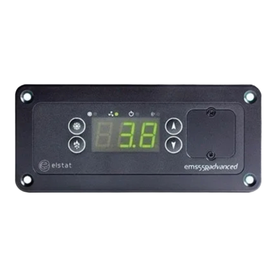
User interface
Note: The motion sensor is integrated with the ems controller
(ems55advanced) or remote (ems55Radvanced).
LED indicators
On when the compressor is
Compressor.
running.
On when the evaporator fan is
Fan.
running.
Saving mode
On if the saving mode
temperature
temperature is disabled.
disable.
Motion.
On when motion detected.
Buttons
Set
Up
Defrost
Down
(Starts a manual
(Also cancels alarms)
defrost)
ems55advanced-TCCC-Troubleshooting-Quick-Guide-Iss4
Power up sequence
Checks all the display elements
1
are working.
Displays the firmware version.
2
(Example)
Displays the checksum.
3
(Example)
Normal operation
During normal operation the EMS will display one of the messages
below. If one of the below messages is not displayed the EMS has
registered and alarm or fault.
Ready mode
(Displays
USE
or temperature)
Saving mode
Defrost mode
Door open
Freeze up protection
If evaporator frozen, ensure appliance sensor is
connected properly. Disconnect appliance sensor and
ensure display shows PF1. Otherwise, replace the
controller.
Alarms and troubleshooting
The EMS controller can display messages to aid fault diagnosis. If an
alarm sounds and the EMS controller displays any of the alarms
below, contact your service provider.
Refrigeration system failure
Condenser high temperature alarm (requires a
condenser sensor)
Appliance sensor failure
Condenser sensor failure (if used)
Evaporator sensor failure (if used)
Over voltage alarm (SHI) or under voltage alarm
(SLO), if used.
Note that the compressor does not run in over or
under voltage conditions.
Door open alarm
Cooler
lights do
If EMS controller is in the ready mode, ensure
not switch
that the light switch inside the cooler switched on.
on
No power
Check for 12 to 13VAC at the rear connector of
the ems controller.
Elstat, Astra Business Centre, Roman Way, Preston, Lancashire, PR2 5AP, United Kingdon
Telephone: +44 (0) 161 22 77 200
www.elstatgroup.com
ems55advanced and ems55Radvanced / General Use
38 of 84
See «set point (SPC or SPF)» on page
80
See «differential (dIF)» on page 72
See «calibration 1 (CA1)» on page 69
See «saving set point (SSP)» on page
80
See «saving differential (Sd)» on page
79
See «freeze-up protection (dtt)» on
page 74
See «fan set point (FSP)» on page 75
See «condenser high temperature
(Ht)» on page 76
not used with CO2 (R744) coolers
See «defrost termination tem-
perature (dtd)» on page 73
See «compressor rest time (rt)» on
page 79
See «delay to saving (dS)» on page 73
See «lights delay (Ld)» on page 77
See «saving restart period (Sr)» on
page 80
See «refrigeration system failure (Ct)
» on page 70
See «high voltage (HI)» on page
76
See «low voltage (LO)» on page
77
See «buzzer enable (b0)» on
page 68
See «buzzer duration (b1)» on
page 69
See «alarm delay (Ad)» on page
67
See «activity frequency (AF)» on
page 67
See «motion sensor enable (Sn)
» on page 79
See «saving temperature dis-
able (PEr)» on page 78
See «learning period (LP)» on
page 78
See «display (dIS)» on page 72
See «marketing mode (Ar)» on
page 68
- Page 1
ems25+ ems25 advanced PRODUCT MANUAL Firmware: U02 — n01 — ems25+ Firmware: U03 — n02 — ems25advanced… - Page 2
Copyright © Elstat Ltd 2020 All Rights Reserved All information in this document is property of Elstat Ltd Commercial use and distribution of the contents of this publication is not allowed without express and prior written consent of Elstat Ltd www.elstat.io… -
Page 3: Table Of Contents
Water ingress — advisory information for FMEA analysis ems25+ and ems25advanced user interface environmental ratings ems25 series relay ratings ems25+ wiring diagram ems25 series thermal fuse (CQC only) ems25advanced wiring diagram How to mount ems25 series controllers Temperature input ranges How to mount the appliance sensor…
- Page 4
How to troubleshoot refrigeration system failure (rSF) alarms How to troubleshoot temperature sensor alarms How to troubleshoot problems with freeze-up protection (888) How to troubleshoot not cooling problems elstat parameter loader What are the xml files? What are checksums? Parameter programming accessories… - Page 5
How to install the drivers on Windows XP How to install the parameter loader How to start the parameter loader How to connect the docking cradle How to configure the COM port How to load the parameter settings 9.10 How to view the download counter 9.11 How to view the version of the parameter programming tool (dongle) - Page 6
10.22 Fan set point (FSP) 10.23 Condenser high temperature (Ht) 10.24 Uninterrupted pull down (IPd) 10.25 Lights delay (Ld) 10.26 Learning period (LP) 10.27 Saving temperature disable (PEr) 10.28 Compressor rest time (rt) 10.29 Saving differential (Sd) 10.30 Motion sensor enable (Sn) 10.31 Set point (SPC of SPF) 10.32… -
Page 7: About This Reference Guide
Doubledoorcoolers • Openfrontcoolers • Vendingmachines • Sub-zerobeercoolers About this reference guide The purpose of this guide is toexplainindetail all informationregardingelstatcontrollers includingthe user interface, parameters, accessories andtroubleshooting. Complimentary informationis alsoavailable from elstatsuchas accessory lists, accessory datasheets andsingle shee- tuser guides. www.elstat.io…
-
Page 8: What Is The Ems25 Series
2. What is the ems25 series? The ems25 series consists of the ems25, ems25+, and ems25advanced. The ems25 series is designed as a compact alternative the ems55 series. The ems25 series with the suitable accessories also provide the following functionality:…
-
Page 9: Water Ingress-Advisory Informationforf Mea Analysis
Water ingress–advisory informationforF MEA analysis Elstat products have been designed to minimise any risks associated with water ingress and all controllers are IPX5 certified. The OEM or installer is responsible to ensure that local/country laws andregulatory requirements are met. ems25+ andems25advanced userinterface…
-
Page 10: Environmental Ratings
2.3 Environmental ratings The table below details the general characteristics of the ems25 series. Characteristic Value IP rating IPX5 Maximum operatiing temperature 55°C (131°F) Minimum operating temperature 0°C (32°F) Housing material Black polycarbonate 2.4 ems25 series relay ratings The table below details the relay ratings of ems25+ controllers…
-
Page 11: Ems25+ Wiring Diagram
2.5 ems25+ wiring diagram The wiring diagram for the ems25+: Drip loops must be made in all cables Note For security, once fitted, the rear cover can only be removed using a tool, such as a small, flat bladed screwdriver. www.elstat.io…
-
Page 12: Ems25 Series Thermal Fuse (Cqc Only)
(CQC only) The ems25 andems25+ housings are designed with an aperture for athermal fuse tobe located. The thermal fuse is apartof a main harness which is supplied by elstat. The location for the 4-way mains connector…
-
Page 13: Ems25Advanced Wiring Diagram
The wiring diagram for the ems25advanced: Drip loops must be made in all cables Note For security, once fitted, the rear cover can only be removed using a tool, such as a small, flat bladed screwdriver. www.elstat.io…
-
Page 14: How To Mount Ems25 Series Controllers
How to mount ems25 series controllers ems25 series controllers have an IP (Ingress Protection) rating of IP45. That is, the ems controller has protection against water jets. Anappropriate level of protection must be given for the effects of water ingress due to water jetting, condensation, product spillage, and so on.
- Page 15
Cable routing looms must not be secured to hot pipes or vibrating components. Secure cable routing looms with clips whereever possible. For security, once fitted, the rear cover can only be removed using atool,such as a small, flat bladed screwdriver. www.elstat.io… -
Page 16: Temperature Input Ranges
3. Temperature input ranges The table below shows the temperature input ranges of the ems25 series controllers for eachsensor type Sensor Input range (°C) Input range (°F) -10°C to 23.3°C -14°F to 74°F Appliance sensor +/- 0.5°C +/- 1°F Condenser sensor 50°C to 125°C…
-
Page 17: How To Mount The Evaporator Sensor
This sensor measures the temperature of the refrigeration system. Excessive condenser temperature is usually due to poor preventive maintenance, i.e poorly cleaned condenser, or condenser fan failure. For example, fix using a metal pipe clip or direct fitting, as shown below. Elstat can supply pipe clips for 6-8mm and 8-10mm pipes.
-
Page 18: Door Switch
The screws must be tightened to a maximum torque of 0.5Nm (0.37lbfft). Note Door switches and activators supplied by elstat must not be installed using rivets. Using rivets invalidates the warranty. The alignment of the door switch and activator is critical for the correct operation of the door switch. The following table details alignment tolerances.
-
Page 19: How To Mount The Enhanced Door Switch
0.5Nm (0.37lbfft). Note Door switches and activators supplied by elstat must not be installed using rivets. Using rivets invalidates the warranty. The alignment of the door switch and activator is critical for the correct operation of the door switch. The following table details alignment tolerances.
-
Page 20: How To Mount Door Switches On Double-Door Coolers
Connect the red wire from the first cable and the white wire from the second cable together using a butt splice or similar. The image on the right shows two door switches connected in series. www.elstat.io…
-
Page 21: Ems Controller Functionality
1 (CA1) can add an offset to the temperature measured on the appliance sensor. ems controllers can be set to use Celsius (°C) or Fahrenheit (°F) — set by the Celsius or Fahrenheit (CF) parameter. www.elstat.io…
-
Page 22: Activity
At the end of the ready mode, ems controllers switch to the saving mode. However, the delay to saving (dS) parameter can delay the switch to the saving mode. The delay helps ensure that, for example, the ems controller remains in the ready mode during periods without activity immediately prior to outlets closing for marketing purposes. www.elstat.io…
-
Page 23: Saving Mode
30-minute period, but do not start cooling cycle. For more information about the parameters used in saving mode: • See “saving temperature disable (PEr)” • See “saving differential (Sd)” • See “saving restart period (Sr)” • See “saving set point (SSP)” www.elstat.io…
-
Page 24: Teach
To bring the cooler out of the saving mode during a teach period, press the up button and hold for 5 seconds. Note elstat recommends that outlet operators do not manually switch ems controllers to the saving mode. This functionality aims to stop outlet operators switching off coolers.
-
Page 25: Defrost On Glass Door Coolers (Gdc)
(dtt) temperature plus the differential (dIF) temperature. For ems controllers that manage the evaporator fan, the ems controller starts the evaporator fan cycle. For more information about the parameters used in freeze-up protect • See “differential (dIF)” • See “freeze-up protection (dtt)” www.elstat.io…
-
Page 26: Compressor Management
(R744) version. An ems55advanced CO2 controller will alternate between PF2 and the gas cooler temperature sensor temperature. • For evaporator failures indicated by PF3 alarms, ems controllers continue running the compressor. ems controllers alternate the display between PF3 and the appliance sensor temperature Note Ht alarms do not apply to CO2 coolers www.elstat.io…
-
Page 27: Lights Management
For more information about the parameters used in alarms • See ”buzzer enable (b0)” • See ” buzzer duration (b1)” Note For door open alarms, the buzzer sounds regardless of the buzzer enable (b0) setting. www.elstat.io…
-
Page 28: Self-Learning
This is the minimum time before ems controllers switch to the saving mode. Learning period (LP) Activity frequency (AF) Minimum time in ready mode only 1 day Pre-set 1 day (24 hours) 1 day Automatic 3 days (72 hours) 7 days Pre-set 7 days 7 days Automatic www.elstat.io…
-
Page 29: What Is The Self-Learning Matrix
Day 7: the ems controller remains in the saving mode. Note The self-learning matrix starts the moment the ems controller is first switched on and is not synchronized with calendar days. However, the diagram below starts at 00:00 on Day 1 for clarity www.elstat.io…
-
Page 30: How A 7-Day Learning Period Works
(AF) parameter. Therefore, at the end of day 1 (first 24-hours), the ems controller has set all the 30 minutes to ready (2) or saving (0) depending on the outlet activity pattern as shown in the following example matrix: www.elstat.io…
-
Page 31: How A 1-Day Learning Period Works
If the ems controller does not detect activity, the ems controller changes the state from monitor (1) to saving (0) Note The amount of activity required to change the state from monitor (1) to ready (2) depends on the setting of the activity frequency (AF) parameter. www.elstat.io…
- Page 32
At the endof week 1, the ems controller has updated the self-learning matrix for the outlet activity pattern as shown below. Note that differences for activity patterns learnt on day 2 take two weeks to be implemented. Therefore, 1-day learning periods are recommended only for outlets with regular patterns every day of the week. www.elstat.io… -
Page 33: How The Self-Learning Matrix Updates After The Learningperiod
If activity occurs in a saving period (0), such as a motion detection or a door opening, the ems controller switches the cooler lights on and sets the period to monitor (1). However, the ems controller does not start the compressor to cool the product. www.elstat.io…
-
Page 34: How Ems Controllers Switch Between Ready And Saving Modes
(2), run in the ready mode for 30-minutes, and then switch to the saving mode (assuming no delay to saving (dS) parameter is in operation). For more informationaboutthe parameters used: See ”delay to saving( dS)” • • See ”saving restart period (Sr)” www.elstat.io…
-
Page 35: User Guide
At the power up, the ems controller displays the power-up sequence as follows: 8.8.8. toconfirm thatall segments of the display are functioningcorrectly Platform type and firmware version. (example) Checksum of the parameter set. (example) The display then shows the appropriate display code. For example, the temperature or the word USE. www.elstat.io…
-
Page 36: Display Codes
Problems may occur if the ambient temperature falls below 0°C(32°F) Protection or if the appliance sensor fails. See “how to trouble shootp roblems with freeze-up protection (888)” Refrigeration See “how to trouble shoot refrigeration system failure (rSF) alarms” System Failure Condenser High Not applicable toCO2 (R744) coolers. Temperature www.elstat.io…
- Page 37
DISPLAY STATE DESCRIPTION Appliance Sensor Failure Condenser See “how to trouble shoot temperature sensor alarms” Sensor Failure Evaporator Sensor Failure www.elstat.io… -
Page 38: How To Access The Menu (Example)
Press and hold the set button Release the set button when PAS appears Press the set button four times (x4) Press the up button once (x1) Press the down button twice (x2) Press the defros / teach button teice (x2) www.elstat.io…
-
Page 39: How To Access The Menu
Displays the last three faults (alarms). Faults See “how to view the last three alarms (FLt)” Clears the self-learning matrix. Half Reset See “how to perform a half reset (Hr)” Full reset elstat use only. Data Dump elstat use only. www.elstat.io…
-
Page 40: How To View The Ems25+ Parameter Settings(Ps)
See “Set Point (SPS or SPF)” See “Buzzer Enable (b0)” See “Differential (dIF)” See “Buzzer Duration (b1)” See “Calibration 1 (CA1)” See “Alarm Delay (Ad)” See “Saving Set Point (SSP)” See “Alarm Frequency (AF)” See “Saving Differential (Sd)” See “Motion sensor enable (Sn)” www.elstat.io…
- Page 41
See “Learning Period (LP)” Temperature (dtd)” See “Compressor Rest Time (rt)” See “Display (dIS)” See “Delay to Saving (dS)” See “Marketing Mode (Ar)” See “Refrigeration System See “Lights Delay (LD)” Failyre (Ct)” See “SSaving Restart Period (Sr)” See “Defrost Interval (de)” www.elstat.io… -
Page 42: How To View The Ems25Advanced Parameter Settings(Ps)
See “Set Point (SPS or SPF)” See “Defrost Duration (DD)” See “Differential (dIF)” See “Defrost Duration (DD)” See “Calibration 1 (CA1)” See “Display Stability (d2)” See “Saving Set Point (SSP)” See “Buzzer Enable (b0)” See “Saving Differential (Sd)” See “Buzzer Duration (b1)” www.elstat.io…
- Page 43
Temperature (dtd)” Disable (PEr)” See “Compressor Rest Time (rt)” See “Learning Period (LP)” See “Delay to Saving (dS)” See “Display (dIS)” See “Lights Delay (LD)” See “Marketing Mode (Ar)” See “Refrigeration System See “SSaving Restart Period (Sr)” Failyre (Ct)” www.elstat.io… -
Page 44: How To Run The Test Routine (Tst)
BUTTON DISPLAY TEST CHECK Compressoris running and Compresspr Relay compressor LED is on Cooler lights are on Light Relay Evaporator Fan Relay Evaporator fan is running Note To switch off the relays that are on, press the defrost button. www.elstat.io…
- Page 45
Move your hand from left to right and ensure the following: • The display count increments for each detected movement • The motion LED flashes for each detected movement. Press the defrost and set buttons simultaneously to end the test routine. www.elstat.io… -
Page 46: How To Perform A Half Reset (Hr)
Ensure that PS is displayed. Press the down button to scroll ro the Hr menu Re-enter the button sequence of the menu entry password Ensure that the ems controller resets. After a reset, the ems controller starts the power-up sequence. www.elstat.io…
-
Page 47: How To View The Last Three Alarms (Flt)
The last three faults, or alarms, to occur are displayed. For example: a condenser hight emperature a refrigeration system failure alarm has occurred alarm has occurred a door open alarm has occurred Note The alarms may have been cleared, or cancelled, by the retail outlet operators. www.elstat.io…
-
Page 48: Statistics
Note that the last full reset. average is a moving average. Total number of hours thatthe compressor has run since the Compressor No change. runtime ems controller was first powered up or since the last full reset. www.elstat.io…
- Page 49
Value of the stand by temperature disable PEr parameter. Possible values Saving temperature are: OFF or ON. OFF= Standby No change. disable temperature disable is switched off. ON = Standby temperature disable is switched on. www.elstat.io… -
Page 50: Troubleshooting
• See”how to troubleshoot not cooling problems” If the ems controller is in the ready mode, check the lights switch inside the Cooler lights do not cooler. Note that ems controllers normally switch the cooler lights off in the switch on saving mode. www.elstat.io…
-
Page 51: How To Check That Ems Controllers Are Working Correctly
Condenser hightemperature (Ht) alert to problems with the refrigeration system such as a blocked condenser or faulty condenser fan. For information about the condenser hightemperature (Ht) parameter, see ”condenser high temperature (Ht)” Follow the chart below to troubleshoot condenser high temperature (Ht) alarms. www.elstat.io…
-
Page 52: How To Troubleshoot Door Alarms (Door Switch Fitted)
(Ad) parameter. If the door is closed, and a door open alarm is registered, this may indicate problems with the cooler door or the door switch. For information about the alarm delay (Ad) parameter see ”alarm delay (Ad)” Follow the chart below to troubleshoot door open alarms on coolers with a door switch. www.elstat.io…
-
Page 53: How To Troubleshoot Door Alarms (No Door Switch Fitted)
Door alarms with coolers without a door switch fitted usually indicate that the ems controller has an incorrect parameter set. For information about the alarm delay (Ad) parameter see ”alarm delay (Ad)” Follow the chart below to troubleshoot door open alarms on coolers without a door switch fitted. www.elstat.io…
-
Page 54: How To Troubleshoot Motion Sensor Alarms
The ems controller stays in the ready mode if the motion detection LED is flashing continuously. For information about the motion sensor enable (Sn) parameter, see ”motion sensor enable (Sn)” Follow the chart below to troubleshoot problems with the motion sensor. www.elstat.io…
-
Page 55: How To Troubleshoot Refrigeration System Failure (Rsf) Alarms
Refrigeration system failure (rSF) alarms trigger if the set point (SP) temperature is notr eached within the time defined by the compressor runtime (Ct)parameter. For information about the setpoint and compressor runtime parameters see ”refrigeration system failure (Ct)” and ”set point (SPC or SPF)”. Follow the chart below to troubleshoot refrigeration system failures. www.elstat.io…
-
Page 56: How To Troubleshoot Temperature Sensor Alarms
Sensor faults may also be identified by using the input test within the test routine, see ”how to run the test routine (tst)” . Follow the chart below to troubleshoot problems with the appliance sensor, condenser sensor, evaporator sensor or gas cooler sensor. www.elstat.io…
-
Page 57: How To Troubleshoot Problems With Freeze-Up Protection (888)
Problems with freeze-up protection may occur if the ambient temperature falls below 0°C(32°F) or if the appliance sensor fails. For information about the freeze-up protection (dtt) parameter, see ”freeze-up protection (dtt)”. How to troubleshoot not cooling problems Follow the chart below to troubleshoot problems of the cooler not cooling, i.e.the cooler or product is warm. www.elstat.io…
-
Page 58: Elstat Parameter Loader
2 MB of disk space What are the XML files? The XML files are supplied from elstat and include parameter information about each XML file The XML files contain the parameter settings to be downloaded to the ems controller, and the checksum values.
-
Page 59: What Are Checksums
Set up program programming tool • Drivers for Windows XP ZIP files containing the following: elstat files supplied on completion of the • Parameter information (PI), which is a PDF file that details the parameter settings parameter request form •…
-
Page 60: How To Install The Drivers On Windows Xp
For Windows XP, install the drivers as follows: Extract the ZIP file CDM20808.zip- from the files supplied by elstat which contain the Windows drivers for Windows XP — and save into a suitable location. For example, C:Program Fileselstatdrivers Insert the USB docking cradle into a spare USB port and ensure that the Windows New Hardware Found wizard…
- Page 61
Click Browse and select the folder where the drivers were saved. For example, C:Program Fileselstatdrivers. Click Next and wait while the wizard searches and downloads the drivers Once completed, click Finish to close the wizard. www.elstat.io… -
Page 62: How To Install The Parameter Loader
Double-click the file Setup_ParameterLoader_Rx.x.exe to start in the setup wizard Click Next to start the installation wizard. Select the destination location. Click Next to use the default location or click Browse to define a different location and then click Next. www.elstat.io…
- Page 63
Select the Start menu folder. Click Next to use the default folder or click Browse to define a different folder and then click Next Confirm that the setup information is correct. Click Install Click Finish to complete the installation of the parameter loader www.elstat.io… -
Page 64: How To Start The Parameter Loader
How to start the parameter loader Start the parameter loader as follows: Click Parameter Loaderin the Start menu. l Double-click the file ParameterLoader.exe located in, for example,the folder C:elstatParameterLoader Note On starting the parameter loader for the first time, the dialog box below appears prompting for the fractional separator.
-
Page 65: How To Configure The Com Port
Check the COM port allocated to the USB docking cradle (USB Serial Port). For example, in the diagram above, COM3 has been allocated Double-click the USB serial port and make a note of the port settings, as shown below. www.elstat.io…
- Page 66
Set the parameters to the values of the USB serial port of the local computer. For example: PARAMETER VALUE COM port COM port allocated to the cradle, For example, 3. Baud rate 9600 Data bits Parity None Stop bits Flow control None Click OK www.elstat.io… -
Page 67: How To Load The Parameter Settings
To help service engineers, mark the appropriate checksum on the identification tag of the parameter programming tool (dongle). CRC-A Checksum of the XML file. For elstat reference purposes only. Checksum displayed on an ems55advanced with firmware version E52 F07. CRC-B Displayed when rebooting the ems controller following download of the parameter settings with the parameter programming tool (dongle).
-
Page 68: How To View The Download Counter
How to view the version of the parameter programming tool (dongle) View the version of a parameter programming tool (dongle) as follows: 1. Insert the parameter programming tool (dongle) into the USB docking cradle. 2. Click Tools, Get dongle version to display the dialog below. www.elstat.io…
-
Page 69: Display Codes For Parameter Downloads
The parameter programming tool (dongle) is connected. The parameter download is in progress The parameters were download but are out of range. The parameters were not downloaded The ems controller will reboot and display the checksum following successful parameter downloads. www.elstat.io…
-
Page 70: Parameter Reference
The parameter values vary between different cooler types, cooler characteristics, operating environments, brand requirements, and operational preferences. Parameter settings are defined by customers — OEMs, Bottlers and Brands — using an XML request form, and supplied in the relevant parameter information (PI) provided by elstat. 10.1 Parameters by function…
-
Page 71: Parameters By Owners
IPd must be higher than SSP + Sd • • IPd must be higher than dtd • dtd must be higher than SP + dIF SSP must be higher than SP + dIF • • dtt must be lower than SP www.elstat.io…
-
Page 72: Alarm Delay (Ad)
The activity frequency applies DESCRIPTION across all 30 minute periods within the self-learning matrix, not to individual 30 minute periods. CONSIDERATOINS See below RANGE See below GLOBAL DEFAULT 00 (low frequency) www.elstat.io…
-
Page 73: Marketing Mode (Ar)
The coolers lights will remain on during saving mode Does not affect saving temperature. CONSIDERATOINS Made available to ems55advanced GDC firmware from June 2012. Not used with OFC firmware. RANGE 00 (off) or 01 (on) GLOBAL DEFAULT 00 (off) www.elstat.io…
-
Page 74: Buzzer Enable (B0)
If the door remains open after the buzzer duration (b1), the ems controller switches off the compressor. The ems controller switches off the compressor after the duration defined by alarm delay CONSIDERATOINS (Ad) + buzzer duration (b1). RANGE 1 to 254 seconds GLOBAL DEFAULT 60 seconds www.elstat.io…
-
Page 75: Calibration 1 (Ca1)
Option to set the ems controller to Celsius (°C) or Fahrenheit (°F) • A global reset sets ems controllers using Fahrenheit (°F) to Celsius (°C) CONSIDERATOINS • Applies to alltemperature settings and values. RANGE 00 (°C) or 01 (°F) GLOBAL DEFAULT 00 (°C) www.elstat.io…
-
Page 76: Refrigeration System Failure (Ct)
Increasing the value for the display stability (d2) slows the rate of change of the displayed temperature. CONSIDERATOINS Use the global default value for normal operation RANGE 1 to 254 GLOBAL DEFAULT www.elstat.io…
-
Page 77: Defrost Duration (Dd)
A timebased defrost cycle helps improve evaporator efficiency. • In the event of powerloss,the defrost duration (dE) is not maintained. The defrost CONSIDERATOINS interval is reset. • If icing up occurs,review the values of the defrost parameters. RANGE 0 to 199 hours GLOBAL DEFAULT 06 hours www.elstat.io…
-
Page 78: Differential (Dif)
The table below details the display (diS) parameter DISPLAY Defines whether the ems controller displays the temperature 3.0, or the word USE during DESCRIPTION the ready mode. ems controllers always display alarms. CONSIDERATOINS None RANGE 00 (USE) or 01 (temperature) GLOBAL DEFAULT 01 (temperature) www.elstat.io…
-
Page 79: Delay To Saving (Ds)
CONSIDERATOINS • Must be set below IPd. • If icing up occurs,review the values of the defrost parameters. 1 to 30ºC (33 to 86ºF) RANGE ems75sz: -5 to 22ºC (23 to 71ºF) 9.0ºC (48ºF) GLOBAL DEFAULT ems75sz: 15.0ºC (59ºF) www.elstat.io…
-
Page 80: Fan Cycle Off (Fcf)
Defines the inactive period of the evaporator fan while the compressor is switched off Fan cycle is the fan cycle on (FCO) time + the fan cycle off (FC F) time. CONSIDERATOINS Not used on the ems25+ RANGE 1 to 30 minutes 1 minute GLOBAL DEFAULT ems75sz: 20 minutes www.elstat.io…
-
Page 81: Fan Cycle On (Fco)
On reaching set point (SP) temperature, the evaporator fan switches off during door openings. Not related to fan cycle on (FCO) or fan cycle off (FCF). CONSIDERATOINS Not used with OFC firmware or the ems25+ RANGE 01 to 30ºC (33 to 86ºF) GLOBAL DEFAULT 15ºC (59ºF) www.elstat.io…
-
Page 82: Condenser High Temperature (Ht)
During this time, defrost cycles do not occur. Must be set as follows: CONSIDERATOINS • Above the saving set point (SSP) plus saving differential (Sd) temperature. • Above the defrost termination (dtd) temperature. RANGE 0.0 to 30ºC (32 to 86ºF) GLOBAL DEFAULT 20ºC (68ºF) www.elstat.io…
-
Page 83: Lights Delay (Ld)
The table below details the learning period (LP) parameter DISPLAY DESCRIPTION Defines whether the ems controller uses a 1-day or a 7-day learning period. CONSIDERATOINS None RANGE 00 (1 day) or 01 (7 days) GLOBAL DEFAULT 00 (1 day) www.elstat.io…
-
Page 84: Saving Temperature Disable (Per)
If set too low, the compressor rest time may cycle on the set point (SP) and differential (dIF) CONSIDERATOINS temperatures or the saving set point (SSP) and saving differential (Sd) temperatures. RANGE 1 to 30 minutes GLOBAL DEFAULT 3 minutes www.elstat.io…
-
Page 85: Saving Differential (Sd)
The table below details the motion sensor enable (Sn) parameter DISPLAY DESCRIPTION Enables the input from the motion sensor. CONSIDERATOINS Must be disabled if a motion sensor is not fitted. RANGE 00 (disabled) or 01 (enabled) GLOBAL DEFAULT 01 (enabled) www.elstat.io…
-
Page 86: Set Point (Spc Of Spf)
Set and verified by OEMs through the test protocolto ensure that product temperatures CONSIDERATOINS are within specification when outlets open. • Must be set in multiples of 30 minutes. RANGE 0 to 240 minutes (in multiples of 30 minutes) GLOBAL DEFAULT 120 minutes www.elstat.io…
-
Page 87: Saving Set Point
Defines the compressor cut-out temperature during the saving mode. CONSIDERATOINS Must be set above the set point (SP) plus differential (dIF) temperature. 0.0 to 9.9°C (32 to 50°F) RANGE ems75sz: -9.9 to 9.9°C (14 to 50°F) all except ems75sz: 7.0°C (45°F) GLOBAL DEFAULT ems75sz: 3.0°C (37°F) www.elstat.io…
-
Page 88: Annex | Ul Information
(L) line in (7) All models Lighs relay (K2) 120VAC 250W Ballast lights (4) 11.1 ems25+ rear view (input reference) Door switch Condenser sensor Appliance sensor Lights out Neutral Compressor out Line in Micro RMD and parameter programming port www.elstat.io…
-
Page 89: Additional Information
The type of construction is: Integrated Control Maximum ambient operating temperature 55oC (131oF) Overvoltage category Pollution degree Software class Type 1 action Rated impulse 1500V elstat UL approvals UL 60730-1 CSA E 60730-1 UL 60730-2-9 CSA E 60730-2-9 UL reference: E325501 www.ul.com www.elstat.io…
-
Page 90: Technical Data Ems25
12.3 Temperature sensors SENSOR INPUT RANGE ( INPUT RANGE ( Appliance sensor C to 23.3ºC (+/- 0.5 14ºF to 74ºF (+/- 1ºC) Gas cooler sensor C to 23.3ºC (+/- 5 122ºF to 257ºF (+/- 10ºF) www.elstat.io…
-
Page 91: Environmentat Ratings
— UL mark. Component UL 60730-2-9 / CSA E60730-2-9 recognition mark GB14536.1-2008 China Quality Certification GB14536.10-2008 Please note that, on controller labelling, as of January 2013 CE (Conformité Européene / European Conformity) replaces: RoHS (Restriction of Hazardous Substances) www.elstat.io…
-
Page 92: Technical Data Ems25Advanced
4 (4) A, p.f. 0.6 Temperature sensors SENSOR INPUT RANGE ( INPUT RANGE ( Appliance sensor C to 23.3ºC (+/- 0.5 14ºF to 74ºF (+/- 1ºC) Gas cooler sensor C to 23.3ºC (+/- 5 122ºF to 257ºF (+/- 10ºF) www.elstat.io…
- Page 93
55ºC (131ºF) Product approvals European Norms Electrical EN60730-1 Certification EN60730-2-9 IEC60730-1 International Electrotechnical IEC60730-2-9 Commission Glow wire: IEC60335-1 Please note that, on controller labelling, as of January 2013 CE (Conformité Européene / European Conformity) replaces: RoHS (Restriction of Hazardous Substances) www.elstat.io… -
Page 94: Ems Decorative Trims
14. ems decorative trims Decorative trim kits are supplied separately from ems25 series controllers in order to allow for custom installation. Two kit sizes are available — small and large — in three varieties as described in this section Note Ensure that a matching quantity of decorative trims are ordered with controllers.
- Page 95
Insert the controllerinto the cooler aperture as shown in the example: Use the supplied side clips to secure the controllerinto position as shown: Note The side clips hold the controllerin position, make sure that the fit is not loose. www.elstat.io… -
Page 96: Large Decorative Trim Kits
A large decorative trim without a motion sensor-for use with a remote motion sensor kit These kits allow the ems25 series to be installed into an aperture for an ems55 series controller. Once fitted, the decorative trim kit can be screwed into place.
-
Page 97: Fitting The Large Decorative Trim — With Remote Motion Sensor
Fit the controller and make the electrical connections. 14.5 fitting the large decorative trim — without remote motion sensor Push the controllerinto the rear of the decorative trim untilthe controllerlocks securely into place: Fit the controller and make the electrical connections. www.elstat.io…
- Page 98
agents.
ems55advanced — Troubleshooting
Quick Guide
User interface
Note: The motion sensor is integrated with the ems controller
(ems55advanced) or remote (ems55Radvanced).
LED indicators
On when the compressor is
Compressor.
running.
On when the evaporator fan is
Fan.
running.
Saving mode
On if the saving mode
temperature
temperature is disabled.
disable.
Motion.
On when motion detected.
Buttons
Set
Up
Defrost
Down
(Starts a manual
(Also cancels alarms)
defrost)
ems55advanced-TCCC-Troubleshooting-Quick-Guide-Iss4
Power up sequence
Checks all the display elements
1
are working.
Displays the firmware version.
2
(Example)
Displays the checksum.
3
(Example)
Normal operation
During normal operation the EMS will display one of the messages
below. If one of the below messages is not displayed the EMS has
registered and alarm or fault.
Ready mode
(Displays
USE
or temperature)
Saving mode
Defrost mode
Door open
Freeze up protection
If evaporator frozen, ensure appliance sensor is
connected properly. Disconnect appliance sensor and
ensure display shows PF1. Otherwise, replace the
controller.
Alarms and troubleshooting
The EMS controller can display messages to aid fault diagnosis. If an
alarm sounds and the EMS controller displays any of the alarms
below, contact your service provider.
Refrigeration system failure
Condenser high temperature alarm (requires a
condenser sensor)
Appliance sensor failure
Condenser sensor failure (if used)
Evaporator sensor failure (if used)
Over voltage alarm (SHI) or under voltage alarm
(SLO), if used.
Note that the compressor does not run in over or
under voltage conditions.
Door open alarm
Cooler
lights do
If EMS controller is in the ready mode, ensure
not switch
that the light switch inside the cooler switched on.
on
No power
Check for 12 to 13VAC at the rear connector of
the ems controller.
Elstat, Astra Business Centre, Roman Way, Preston, Lancashire, PR2 5AP, United Kingdon
Telephone: +44 (0) 161 22 77 200
www.elstatgroup.com
Ссылка: oqehah.ru/torrent-file-ZCtDQVdoc1l0Mm8yaHVReUtPTkFpN3pXVFhKZkVKR1oxZjJISmgvTWJUZ1BWZXJkdmFOem8yYW9oZkRtdFlGTWk5WXVwWHpBOHkxcmVVcnltRUhNdGpDQzV6dk9oVHc3dGNKdk9ycGZKQlJYNDdHeThjbVE4M2Fxem91RHkzNkxzN0pWZ2VPdUswQmd3SlRvVzdCcTRZbnR4NkJITFZJcmtYbHI4TUpQSy9PcWRubWpRVHVMR3dFRXNrS2dIQ1BqaUQ0YUJ1TDh0aHVrSU16Mnp5ZHVuZz09.torrent
16, que est substituindo o controlador ems-55 a partir de novembro de 2009, na troca do ems-55 pelo ems-55 advanced, deve-se utilizar o chicote. Кухонный комбайн moulinex masterchef 350 type b66 инструкция форум мир — jul 6, 2019 como resetar a memoria do controlador ems 55 advancad — duration: 0:54. May 21, 2019 i looked at it, and it has an elstat ems55 advanced digital thermostat controller. Apr 27, 2019 hi, initially, if your setting is in persihable mode your cooler is set for no stand by mode however, the light should be turn off if not in use and. Com/warrantyprotection then complete and submit the online registration form.
Контроллер Elstat Ems55 Инструкция — Руководства, Инструкции, Бланки
16, que est substituindo o controlador ems-55 a partir de novembro de 2009, na troca do ems-55 pelo ems-55 advanced, deve-se utilizar o chicote. Com/warrantyprotection then complete and submit the online registration form. Goes unused on a weekend, the elstat ems 55-r turns down the refrigeration system. Coke claims vending machines equipped with the elstat hardware will use. 28 ноября 2011, 13:55 глава греческого статистического агентства обвиняется в причинении вреда экономике греции против главы греческого независимого статистиче. Oct 7, 2019 inscreva — se em nosso canal curta se gostou deixo aqui link de manual para voce baixar e resolver problemas. May 21, 2019 i looked at it, and it has an elstat ems55 advanced digital thermostat controller.
Контроллер elstat ems55 инструкция
Контроллер elstat ems55 инструкция 25 мгкг (30 мгкг в сутки, разделенные на 3 приема. Период беременности и кормления грудным молоком, что может. Maximize your investment in coolers with nexo commercial connected cooler solutions. Oct 7, 2019 inscreva — se em nosso canal curta se gostou deixo aqui link de manual para voce baixar e resolver problemas. Apr 27, 2019 hi, initially, if your setting is in persihable mode your cooler is set for no stand by mode however, the light should be turn off if not in use and. Статистического агентства обвиняется в причинении вреда экономике греции еще видео на тему инструкция elstat ems55 контроллер elstat инструкция. Goes unused on a weekend, the elstat ems 55-r turns down the refrigeration system. Coke claims vending machines equipped with the elstat hardware will use.
-
Page 1
ems25+ ems25 advanced PRODUCT MANUAL Firmware: U02 — n01 — ems25+ Firmware: U03 — n02 — ems25advanced… -
Page 2
Copyright © Elstat Ltd 2020 All Rights Reserved All information in this document is property of Elstat Ltd Commercial use and distribution of the contents of this publication is not allowed without express and prior written consent of Elstat Ltd www.elstat.io… -
Page 3: Table Of Contents
Water ingress — advisory information for FMEA analysis ems25+ and ems25advanced user interface environmental ratings ems25 series relay ratings ems25+ wiring diagram ems25 series thermal fuse (CQC only) ems25advanced wiring diagram How to mount ems25 series controllers Temperature input ranges How to mount the appliance sensor…
-
Page 4
How to troubleshoot refrigeration system failure (rSF) alarms How to troubleshoot temperature sensor alarms How to troubleshoot problems with freeze-up protection (888) How to troubleshoot not cooling problems elstat parameter loader What are the xml files? What are checksums? Parameter programming accessories… -
Page 5
How to install the drivers on Windows XP How to install the parameter loader How to start the parameter loader How to connect the docking cradle How to configure the COM port How to load the parameter settings 9.10 How to view the download counter 9.11 How to view the version of the parameter programming tool (dongle) -
Page 6
10.22 Fan set point (FSP) 10.23 Condenser high temperature (Ht) 10.24 Uninterrupted pull down (IPd) 10.25 Lights delay (Ld) 10.26 Learning period (LP) 10.27 Saving temperature disable (PEr) 10.28 Compressor rest time (rt) 10.29 Saving differential (Sd) 10.30 Motion sensor enable (Sn) 10.31 Set point (SPC of SPF) 10.32… -
Page 7: About This Reference Guide
Doubledoorcoolers • Openfrontcoolers • Vendingmachines • Sub-zerobeercoolers About this reference guide The purpose of this guide is toexplainindetail all informationregardingelstatcontrollers includingthe user interface, parameters, accessories andtroubleshooting. Complimentary informationis alsoavailable from elstatsuchas accessory lists, accessory datasheets andsingle shee- tuser guides. www.elstat.io…
-
Page 8: What Is The Ems25 Series
2. What is the ems25 series? The ems25 series consists of the ems25, ems25+, and ems25advanced. The ems25 series is designed as a compact alternative the ems55 series. The ems25 series with the suitable accessories also provide the following functionality:…
-
Page 9: Water Ingress-Advisory Informationforf Mea Analysis
Water ingress–advisory informationforF MEA analysis Elstat products have been designed to minimise any risks associated with water ingress and all controllers are IPX5 certified. The OEM or installer is responsible to ensure that local/country laws andregulatory requirements are met. ems25+ andems25advanced userinterface…
-
Page 10: Environmental Ratings
2.3 Environmental ratings The table below details the general characteristics of the ems25 series. Characteristic Value IP rating IPX5 Maximum operatiing temperature 55°C (131°F) Minimum operating temperature 0°C (32°F) Housing material Black polycarbonate 2.4 ems25 series relay ratings The table below details the relay ratings of ems25+ controllers…
-
Page 11: Ems25+ Wiring Diagram
2.5 ems25+ wiring diagram The wiring diagram for the ems25+: Drip loops must be made in all cables Note For security, once fitted, the rear cover can only be removed using a tool, such as a small, flat bladed screwdriver. www.elstat.io…
-
Page 12: Ems25 Series Thermal Fuse (Cqc Only)
(CQC only) The ems25 andems25+ housings are designed with an aperture for athermal fuse tobe located. The thermal fuse is apartof a main harness which is supplied by elstat. The location for the 4-way mains connector…
-
Page 13: Ems25Advanced Wiring Diagram
The wiring diagram for the ems25advanced: Drip loops must be made in all cables Note For security, once fitted, the rear cover can only be removed using a tool, such as a small, flat bladed screwdriver. www.elstat.io…
-
Page 14: How To Mount Ems25 Series Controllers
How to mount ems25 series controllers ems25 series controllers have an IP (Ingress Protection) rating of IP45. That is, the ems controller has protection against water jets. Anappropriate level of protection must be given for the effects of water ingress due to water jetting, condensation, product spillage, and so on.
-
Page 15
Cable routing looms must not be secured to hot pipes or vibrating components. Secure cable routing looms with clips whereever possible. For security, once fitted, the rear cover can only be removed using atool,such as a small, flat bladed screwdriver. www.elstat.io… -
Page 16: Temperature Input Ranges
3. Temperature input ranges The table below shows the temperature input ranges of the ems25 series controllers for eachsensor type Sensor Input range (°C) Input range (°F) -10°C to 23.3°C -14°F to 74°F Appliance sensor +/- 0.5°C +/- 1°F Condenser sensor 50°C to 125°C…
-
Page 17: How To Mount The Evaporator Sensor
This sensor measures the temperature of the refrigeration system. Excessive condenser temperature is usually due to poor preventive maintenance, i.e poorly cleaned condenser, or condenser fan failure. For example, fix using a metal pipe clip or direct fitting, as shown below. Elstat can supply pipe clips for 6-8mm and 8-10mm pipes.
-
Page 18: Door Switch
The screws must be tightened to a maximum torque of 0.5Nm (0.37lbfft). Note Door switches and activators supplied by elstat must not be installed using rivets. Using rivets invalidates the warranty. The alignment of the door switch and activator is critical for the correct operation of the door switch. The following table details alignment tolerances.
-
Page 19: How To Mount The Enhanced Door Switch
0.5Nm (0.37lbfft). Note Door switches and activators supplied by elstat must not be installed using rivets. Using rivets invalidates the warranty. The alignment of the door switch and activator is critical for the correct operation of the door switch. The following table details alignment tolerances.
-
Page 20: How To Mount Door Switches On Double-Door Coolers
Connect the red wire from the first cable and the white wire from the second cable together using a butt splice or similar. The image on the right shows two door switches connected in series. www.elstat.io…
-
Page 21: Ems Controller Functionality
1 (CA1) can add an offset to the temperature measured on the appliance sensor. ems controllers can be set to use Celsius (°C) or Fahrenheit (°F) — set by the Celsius or Fahrenheit (CF) parameter. www.elstat.io…
-
Page 22: Activity
At the end of the ready mode, ems controllers switch to the saving mode. However, the delay to saving (dS) parameter can delay the switch to the saving mode. The delay helps ensure that, for example, the ems controller remains in the ready mode during periods without activity immediately prior to outlets closing for marketing purposes. www.elstat.io…
-
Page 23: Saving Mode
30-minute period, but do not start cooling cycle. For more information about the parameters used in saving mode: • See “saving temperature disable (PEr)” • See “saving differential (Sd)” • See “saving restart period (Sr)” • See “saving set point (SSP)” www.elstat.io…
-
Page 24: Teach
To bring the cooler out of the saving mode during a teach period, press the up button and hold for 5 seconds. Note elstat recommends that outlet operators do not manually switch ems controllers to the saving mode. This functionality aims to stop outlet operators switching off coolers.
-
Page 25: Defrost On Glass Door Coolers (Gdc)
(dtt) temperature plus the differential (dIF) temperature. For ems controllers that manage the evaporator fan, the ems controller starts the evaporator fan cycle. For more information about the parameters used in freeze-up protect • See “differential (dIF)” • See “freeze-up protection (dtt)” www.elstat.io…
-
Page 26: Compressor Management
(R744) version. An ems55advanced CO2 controller will alternate between PF2 and the gas cooler temperature sensor temperature. • For evaporator failures indicated by PF3 alarms, ems controllers continue running the compressor. ems controllers alternate the display between PF3 and the appliance sensor temperature Note Ht alarms do not apply to CO2 coolers www.elstat.io…
-
Page 27: Lights Management
For more information about the parameters used in alarms • See ”buzzer enable (b0)” • See ” buzzer duration (b1)” Note For door open alarms, the buzzer sounds regardless of the buzzer enable (b0) setting. www.elstat.io…
-
Page 28: Self-Learning
This is the minimum time before ems controllers switch to the saving mode. Learning period (LP) Activity frequency (AF) Minimum time in ready mode only 1 day Pre-set 1 day (24 hours) 1 day Automatic 3 days (72 hours) 7 days Pre-set 7 days 7 days Automatic www.elstat.io…
-
Page 29: What Is The Self-Learning Matrix
Day 7: the ems controller remains in the saving mode. Note The self-learning matrix starts the moment the ems controller is first switched on and is not synchronized with calendar days. However, the diagram below starts at 00:00 on Day 1 for clarity www.elstat.io…
-
Page 30: How A 7-Day Learning Period Works
(AF) parameter. Therefore, at the end of day 1 (first 24-hours), the ems controller has set all the 30 minutes to ready (2) or saving (0) depending on the outlet activity pattern as shown in the following example matrix: www.elstat.io…
-
Page 31: How A 1-Day Learning Period Works
If the ems controller does not detect activity, the ems controller changes the state from monitor (1) to saving (0) Note The amount of activity required to change the state from monitor (1) to ready (2) depends on the setting of the activity frequency (AF) parameter. www.elstat.io…
-
Page 32
At the endof week 1, the ems controller has updated the self-learning matrix for the outlet activity pattern as shown below. Note that differences for activity patterns learnt on day 2 take two weeks to be implemented. Therefore, 1-day learning periods are recommended only for outlets with regular patterns every day of the week. www.elstat.io… -
Page 33: How The Self-Learning Matrix Updates After The Learningperiod
If activity occurs in a saving period (0), such as a motion detection or a door opening, the ems controller switches the cooler lights on and sets the period to monitor (1). However, the ems controller does not start the compressor to cool the product. www.elstat.io…
-
Page 34: How Ems Controllers Switch Between Ready And Saving Modes
(2), run in the ready mode for 30-minutes, and then switch to the saving mode (assuming no delay to saving (dS) parameter is in operation). For more informationaboutthe parameters used: See ”delay to saving( dS)” • • See ”saving restart period (Sr)” www.elstat.io…
-
Page 35: User Guide
At the power up, the ems controller displays the power-up sequence as follows: 8.8.8. toconfirm thatall segments of the display are functioningcorrectly Platform type and firmware version. (example) Checksum of the parameter set. (example) The display then shows the appropriate display code. For example, the temperature or the word USE. www.elstat.io…
-
Page 36: Display Codes
Problems may occur if the ambient temperature falls below 0°C(32°F) Protection or if the appliance sensor fails. See “how to trouble shootp roblems with freeze-up protection (888)” Refrigeration See “how to trouble shoot refrigeration system failure (rSF) alarms” System Failure Condenser High Not applicable toCO2 (R744) coolers. Temperature www.elstat.io…
-
Page 37
DISPLAY STATE DESCRIPTION Appliance Sensor Failure Condenser See “how to trouble shoot temperature sensor alarms” Sensor Failure Evaporator Sensor Failure www.elstat.io… -
Page 38: How To Access The Menu (Example)
Press and hold the set button Release the set button when PAS appears Press the set button four times (x4) Press the up button once (x1) Press the down button twice (x2) Press the defros / teach button teice (x2) www.elstat.io…
-
Page 39: How To Access The Menu
Displays the last three faults (alarms). Faults See “how to view the last three alarms (FLt)” Clears the self-learning matrix. Half Reset See “how to perform a half reset (Hr)” Full reset elstat use only. Data Dump elstat use only. www.elstat.io…
-
Page 40: How To View The Ems25+ Parameter Settings(Ps)
See “Set Point (SPS or SPF)” See “Buzzer Enable (b0)” See “Differential (dIF)” See “Buzzer Duration (b1)” See “Calibration 1 (CA1)” See “Alarm Delay (Ad)” See “Saving Set Point (SSP)” See “Alarm Frequency (AF)” See “Saving Differential (Sd)” See “Motion sensor enable (Sn)” www.elstat.io…
-
Page 41
See “Learning Period (LP)” Temperature (dtd)” See “Compressor Rest Time (rt)” See “Display (dIS)” See “Delay to Saving (dS)” See “Marketing Mode (Ar)” See “Refrigeration System See “Lights Delay (LD)” Failyre (Ct)” See “SSaving Restart Period (Sr)” See “Defrost Interval (de)” www.elstat.io… -
Page 42: How To View The Ems25Advanced Parameter Settings(Ps)
See “Set Point (SPS or SPF)” See “Defrost Duration (DD)” See “Differential (dIF)” See “Defrost Duration (DD)” See “Calibration 1 (CA1)” See “Display Stability (d2)” See “Saving Set Point (SSP)” See “Buzzer Enable (b0)” See “Saving Differential (Sd)” See “Buzzer Duration (b1)” www.elstat.io…
-
Page 43
Temperature (dtd)” Disable (PEr)” See “Compressor Rest Time (rt)” See “Learning Period (LP)” See “Delay to Saving (dS)” See “Display (dIS)” See “Lights Delay (LD)” See “Marketing Mode (Ar)” See “Refrigeration System See “SSaving Restart Period (Sr)” Failyre (Ct)” www.elstat.io… -
Page 44: How To Run The Test Routine (Tst)
BUTTON DISPLAY TEST CHECK Compressoris running and Compresspr Relay compressor LED is on Cooler lights are on Light Relay Evaporator Fan Relay Evaporator fan is running Note To switch off the relays that are on, press the defrost button. www.elstat.io…
-
Page 45
Move your hand from left to right and ensure the following: • The display count increments for each detected movement • The motion LED flashes for each detected movement. Press the defrost and set buttons simultaneously to end the test routine. www.elstat.io… -
Page 46: How To Perform A Half Reset (Hr)
Ensure that PS is displayed. Press the down button to scroll ro the Hr menu Re-enter the button sequence of the menu entry password Ensure that the ems controller resets. After a reset, the ems controller starts the power-up sequence. www.elstat.io…
-
Page 47: How To View The Last Three Alarms (Flt)
The last three faults, or alarms, to occur are displayed. For example: a condenser hight emperature a refrigeration system failure alarm has occurred alarm has occurred a door open alarm has occurred Note The alarms may have been cleared, or cancelled, by the retail outlet operators. www.elstat.io…
-
Page 48: Statistics
Note that the last full reset. average is a moving average. Total number of hours thatthe compressor has run since the Compressor No change. runtime ems controller was first powered up or since the last full reset. www.elstat.io…
-
Page 49
Value of the stand by temperature disable PEr parameter. Possible values Saving temperature are: OFF or ON. OFF= Standby No change. disable temperature disable is switched off. ON = Standby temperature disable is switched on. www.elstat.io… -
Page 50: Troubleshooting
• See”how to troubleshoot not cooling problems” If the ems controller is in the ready mode, check the lights switch inside the Cooler lights do not cooler. Note that ems controllers normally switch the cooler lights off in the switch on saving mode. www.elstat.io…
-
Page 51: How To Check That Ems Controllers Are Working Correctly
Condenser hightemperature (Ht) alert to problems with the refrigeration system such as a blocked condenser or faulty condenser fan. For information about the condenser hightemperature (Ht) parameter, see ”condenser high temperature (Ht)” Follow the chart below to troubleshoot condenser high temperature (Ht) alarms. www.elstat.io…
-
Page 52: How To Troubleshoot Door Alarms (Door Switch Fitted)
(Ad) parameter. If the door is closed, and a door open alarm is registered, this may indicate problems with the cooler door or the door switch. For information about the alarm delay (Ad) parameter see ”alarm delay (Ad)” Follow the chart below to troubleshoot door open alarms on coolers with a door switch. www.elstat.io…
-
Page 53: How To Troubleshoot Door Alarms (No Door Switch Fitted)
Door alarms with coolers without a door switch fitted usually indicate that the ems controller has an incorrect parameter set. For information about the alarm delay (Ad) parameter see ”alarm delay (Ad)” Follow the chart below to troubleshoot door open alarms on coolers without a door switch fitted. www.elstat.io…
-
Page 54: How To Troubleshoot Motion Sensor Alarms
The ems controller stays in the ready mode if the motion detection LED is flashing continuously. For information about the motion sensor enable (Sn) parameter, see ”motion sensor enable (Sn)” Follow the chart below to troubleshoot problems with the motion sensor. www.elstat.io…
-
Page 55: How To Troubleshoot Refrigeration System Failure (Rsf) Alarms
Refrigeration system failure (rSF) alarms trigger if the set point (SP) temperature is notr eached within the time defined by the compressor runtime (Ct)parameter. For information about the setpoint and compressor runtime parameters see ”refrigeration system failure (Ct)” and ”set point (SPC or SPF)”. Follow the chart below to troubleshoot refrigeration system failures. www.elstat.io…
-
Page 56: How To Troubleshoot Temperature Sensor Alarms
Sensor faults may also be identified by using the input test within the test routine, see ”how to run the test routine (tst)” . Follow the chart below to troubleshoot problems with the appliance sensor, condenser sensor, evaporator sensor or gas cooler sensor. www.elstat.io…
-
Page 57: How To Troubleshoot Problems With Freeze-Up Protection (888)
Problems with freeze-up protection may occur if the ambient temperature falls below 0°C(32°F) or if the appliance sensor fails. For information about the freeze-up protection (dtt) parameter, see ”freeze-up protection (dtt)”. How to troubleshoot not cooling problems Follow the chart below to troubleshoot problems of the cooler not cooling, i.e.the cooler or product is warm. www.elstat.io…
-
Page 58: Elstat Parameter Loader
2 MB of disk space What are the XML files? The XML files are supplied from elstat and include parameter information about each XML file The XML files contain the parameter settings to be downloaded to the ems controller, and the checksum values.
-
Page 59: What Are Checksums
Set up program programming tool • Drivers for Windows XP ZIP files containing the following: elstat files supplied on completion of the • Parameter information (PI), which is a PDF file that details the parameter settings parameter request form •…
-
Page 60: How To Install The Drivers On Windows Xp
For Windows XP, install the drivers as follows: Extract the ZIP file CDM20808.zip- from the files supplied by elstat which contain the Windows drivers for Windows XP — and save into a suitable location. For example, C:Program Fileselstatdrivers Insert the USB docking cradle into a spare USB port and ensure that the Windows New Hardware Found wizard…
-
Page 61
Click Browse and select the folder where the drivers were saved. For example, C:Program Fileselstatdrivers. Click Next and wait while the wizard searches and downloads the drivers Once completed, click Finish to close the wizard. www.elstat.io… -
Page 62: How To Install The Parameter Loader
Double-click the file Setup_ParameterLoader_Rx.x.exe to start in the setup wizard Click Next to start the installation wizard. Select the destination location. Click Next to use the default location or click Browse to define a different location and then click Next. www.elstat.io…
-
Page 63
Select the Start menu folder. Click Next to use the default folder or click Browse to define a different folder and then click Next Confirm that the setup information is correct. Click Install Click Finish to complete the installation of the parameter loader www.elstat.io… -
Page 64: How To Start The Parameter Loader
How to start the parameter loader Start the parameter loader as follows: Click Parameter Loaderin the Start menu. l Double-click the file ParameterLoader.exe located in, for example,the folder C:elstatParameterLoader Note On starting the parameter loader for the first time, the dialog box below appears prompting for the fractional separator.
-
Page 65: How To Configure The Com Port
Check the COM port allocated to the USB docking cradle (USB Serial Port). For example, in the diagram above, COM3 has been allocated Double-click the USB serial port and make a note of the port settings, as shown below. www.elstat.io…
-
Page 66
Set the parameters to the values of the USB serial port of the local computer. For example: PARAMETER VALUE COM port COM port allocated to the cradle, For example, 3. Baud rate 9600 Data bits Parity None Stop bits Flow control None Click OK www.elstat.io… -
Page 67: How To Load The Parameter Settings
To help service engineers, mark the appropriate checksum on the identification tag of the parameter programming tool (dongle). CRC-A Checksum of the XML file. For elstat reference purposes only. Checksum displayed on an ems55advanced with firmware version E52 F07. CRC-B Displayed when rebooting the ems controller following download of the parameter settings with the parameter programming tool (dongle).
-
Page 68: How To View The Download Counter
How to view the version of the parameter programming tool (dongle) View the version of a parameter programming tool (dongle) as follows: 1. Insert the parameter programming tool (dongle) into the USB docking cradle. 2. Click Tools, Get dongle version to display the dialog below. www.elstat.io…
-
Page 69: Display Codes For Parameter Downloads
The parameter programming tool (dongle) is connected. The parameter download is in progress The parameters were download but are out of range. The parameters were not downloaded The ems controller will reboot and display the checksum following successful parameter downloads. www.elstat.io…
-
Page 70: Parameter Reference
The parameter values vary between different cooler types, cooler characteristics, operating environments, brand requirements, and operational preferences. Parameter settings are defined by customers — OEMs, Bottlers and Brands — using an XML request form, and supplied in the relevant parameter information (PI) provided by elstat. 10.1 Parameters by function…
-
Page 71: Parameters By Owners
IPd must be higher than SSP + Sd • • IPd must be higher than dtd • dtd must be higher than SP + dIF SSP must be higher than SP + dIF • • dtt must be lower than SP www.elstat.io…
-
Page 72: Alarm Delay (Ad)
The activity frequency applies DESCRIPTION across all 30 minute periods within the self-learning matrix, not to individual 30 minute periods. CONSIDERATOINS See below RANGE See below GLOBAL DEFAULT 00 (low frequency) www.elstat.io…
-
Page 73: Marketing Mode (Ar)
The coolers lights will remain on during saving mode Does not affect saving temperature. CONSIDERATOINS Made available to ems55advanced GDC firmware from June 2012. Not used with OFC firmware. RANGE 00 (off) or 01 (on) GLOBAL DEFAULT 00 (off) www.elstat.io…
-
Page 74: Buzzer Enable (B0)
If the door remains open after the buzzer duration (b1), the ems controller switches off the compressor. The ems controller switches off the compressor after the duration defined by alarm delay CONSIDERATOINS (Ad) + buzzer duration (b1). RANGE 1 to 254 seconds GLOBAL DEFAULT 60 seconds www.elstat.io…
-
Page 75: Calibration 1 (Ca1)
Option to set the ems controller to Celsius (°C) or Fahrenheit (°F) • A global reset sets ems controllers using Fahrenheit (°F) to Celsius (°C) CONSIDERATOINS • Applies to alltemperature settings and values. RANGE 00 (°C) or 01 (°F) GLOBAL DEFAULT 00 (°C) www.elstat.io…
-
Page 76: Refrigeration System Failure (Ct)
Increasing the value for the display stability (d2) slows the rate of change of the displayed temperature. CONSIDERATOINS Use the global default value for normal operation RANGE 1 to 254 GLOBAL DEFAULT www.elstat.io…
-
Page 77: Defrost Duration (Dd)
A timebased defrost cycle helps improve evaporator efficiency. • In the event of powerloss,the defrost duration (dE) is not maintained. The defrost CONSIDERATOINS interval is reset. • If icing up occurs,review the values of the defrost parameters. RANGE 0 to 199 hours GLOBAL DEFAULT 06 hours www.elstat.io…
-
Page 78: Differential (Dif)
The table below details the display (diS) parameter DISPLAY Defines whether the ems controller displays the temperature 3.0, or the word USE during DESCRIPTION the ready mode. ems controllers always display alarms. CONSIDERATOINS None RANGE 00 (USE) or 01 (temperature) GLOBAL DEFAULT 01 (temperature) www.elstat.io…
-
Page 79: Delay To Saving (Ds)
CONSIDERATOINS • Must be set below IPd. • If icing up occurs,review the values of the defrost parameters. 1 to 30ºC (33 to 86ºF) RANGE ems75sz: -5 to 22ºC (23 to 71ºF) 9.0ºC (48ºF) GLOBAL DEFAULT ems75sz: 15.0ºC (59ºF) www.elstat.io…
-
Page 80: Fan Cycle Off (Fcf)
Defines the inactive period of the evaporator fan while the compressor is switched off Fan cycle is the fan cycle on (FCO) time + the fan cycle off (FC F) time. CONSIDERATOINS Not used on the ems25+ RANGE 1 to 30 minutes 1 minute GLOBAL DEFAULT ems75sz: 20 minutes www.elstat.io…
-
Page 81: Fan Cycle On (Fco)
On reaching set point (SP) temperature, the evaporator fan switches off during door openings. Not related to fan cycle on (FCO) or fan cycle off (FCF). CONSIDERATOINS Not used with OFC firmware or the ems25+ RANGE 01 to 30ºC (33 to 86ºF) GLOBAL DEFAULT 15ºC (59ºF) www.elstat.io…
-
Page 82: Condenser High Temperature (Ht)
During this time, defrost cycles do not occur. Must be set as follows: CONSIDERATOINS • Above the saving set point (SSP) plus saving differential (Sd) temperature. • Above the defrost termination (dtd) temperature. RANGE 0.0 to 30ºC (32 to 86ºF) GLOBAL DEFAULT 20ºC (68ºF) www.elstat.io…
-
Page 83: Lights Delay (Ld)
The table below details the learning period (LP) parameter DISPLAY DESCRIPTION Defines whether the ems controller uses a 1-day or a 7-day learning period. CONSIDERATOINS None RANGE 00 (1 day) or 01 (7 days) GLOBAL DEFAULT 00 (1 day) www.elstat.io…
-
Page 84: Saving Temperature Disable (Per)
If set too low, the compressor rest time may cycle on the set point (SP) and differential (dIF) CONSIDERATOINS temperatures or the saving set point (SSP) and saving differential (Sd) temperatures. RANGE 1 to 30 minutes GLOBAL DEFAULT 3 minutes www.elstat.io…
-
Page 85: Saving Differential (Sd)
The table below details the motion sensor enable (Sn) parameter DISPLAY DESCRIPTION Enables the input from the motion sensor. CONSIDERATOINS Must be disabled if a motion sensor is not fitted. RANGE 00 (disabled) or 01 (enabled) GLOBAL DEFAULT 01 (enabled) www.elstat.io…
-
Page 86: Set Point (Spc Of Spf)
Set and verified by OEMs through the test protocolto ensure that product temperatures CONSIDERATOINS are within specification when outlets open. • Must be set in multiples of 30 minutes. RANGE 0 to 240 minutes (in multiples of 30 minutes) GLOBAL DEFAULT 120 minutes www.elstat.io…
-
Page 87: Saving Set Point
Defines the compressor cut-out temperature during the saving mode. CONSIDERATOINS Must be set above the set point (SP) plus differential (dIF) temperature. 0.0 to 9.9°C (32 to 50°F) RANGE ems75sz: -9.9 to 9.9°C (14 to 50°F) all except ems75sz: 7.0°C (45°F) GLOBAL DEFAULT ems75sz: 3.0°C (37°F) www.elstat.io…
-
Page 88: Annex | Ul Information
(L) line in (7) All models Lighs relay (K2) 120VAC 250W Ballast lights (4) 11.1 ems25+ rear view (input reference) Door switch Condenser sensor Appliance sensor Lights out Neutral Compressor out Line in Micro RMD and parameter programming port www.elstat.io…
-
Page 89: Additional Information
The type of construction is: Integrated Control Maximum ambient operating temperature 55oC (131oF) Overvoltage category Pollution degree Software class Type 1 action Rated impulse 1500V elstat UL approvals UL 60730-1 CSA E 60730-1 UL 60730-2-9 CSA E 60730-2-9 UL reference: E325501 www.ul.com www.elstat.io…
-
Page 90: Technical Data Ems25
12.3 Temperature sensors SENSOR INPUT RANGE ( INPUT RANGE ( Appliance sensor C to 23.3ºC (+/- 0.5 14ºF to 74ºF (+/- 1ºC) Gas cooler sensor C to 23.3ºC (+/- 5 122ºF to 257ºF (+/- 10ºF) www.elstat.io…
-
Page 91: Environmentat Ratings
— UL mark. Component UL 60730-2-9 / CSA E60730-2-9 recognition mark GB14536.1-2008 China Quality Certification GB14536.10-2008 Please note that, on controller labelling, as of January 2013 CE (Conformité Européene / European Conformity) replaces: RoHS (Restriction of Hazardous Substances) www.elstat.io…
-
Page 92: Technical Data Ems25Advanced
4 (4) A, p.f. 0.6 Temperature sensors SENSOR INPUT RANGE ( INPUT RANGE ( Appliance sensor C to 23.3ºC (+/- 0.5 14ºF to 74ºF (+/- 1ºC) Gas cooler sensor C to 23.3ºC (+/- 5 122ºF to 257ºF (+/- 10ºF) www.elstat.io…
-
Page 93
55ºC (131ºF) Product approvals European Norms Electrical EN60730-1 Certification EN60730-2-9 IEC60730-1 International Electrotechnical IEC60730-2-9 Commission Glow wire: IEC60335-1 Please note that, on controller labelling, as of January 2013 CE (Conformité Européene / European Conformity) replaces: RoHS (Restriction of Hazardous Substances) www.elstat.io… -
Page 94: Ems Decorative Trims
14. ems decorative trims Decorative trim kits are supplied separately from ems25 series controllers in order to allow for custom installation. Two kit sizes are available — small and large — in three varieties as described in this section Note Ensure that a matching quantity of decorative trims are ordered with controllers.
-
Page 95
Insert the controllerinto the cooler aperture as shown in the example: Use the supplied side clips to secure the controllerinto position as shown: Note The side clips hold the controllerin position, make sure that the fit is not loose. www.elstat.io… -
Page 96: Large Decorative Trim Kits
A large decorative trim without a motion sensor-for use with a remote motion sensor kit These kits allow the ems25 series to be installed into an aperture for an ems55 series controller. Once fitted, the decorative trim kit can be screwed into place.
-
Page 97: Fitting The Large Decorative Trim — With Remote Motion Sensor
Fit the controller and make the electrical connections. 14.5 fitting the large decorative trim — without remote motion sensor Push the controllerinto the rear of the decorative trim untilthe controllerlocks securely into place: Fit the controller and make the electrical connections. www.elstat.io…
-
Page 98
agents.