- Manuals
- Brands
- Edwards Manuals
- Water Pump
- RV8
Manuals and User Guides for Edwards RV8. We have 6 Edwards RV8 manuals available for free PDF download: Instruction Manual, Parts And Maintenance Manual

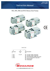
Edwards RV8 Instruction Manual (64 pages)
Rotary Vane Pumps
Brand: Edwards
|
Category: Water Pump
|
Size: 1.4 MB
Table of Contents
-
Table of Contents
3
-
Safety and Compliance
7
-
Definition of Warnings and Cautions
7
-
Safety Symbols
8
-
Introduction
9
-
Scope and Definitions
9
-
ATEX Directive Implications
9
-
Description
10
-
Figure 1 the RV Pump
10
-
Performance Modes and Controls
11
-
Mode Selector
11
-
Gas-Ballast Control
12
-
Construction
12
-
Technical Data
13
-
Operating and Storage Conditions
13
-
Performance
13
-
General
13
-
Performance Characteristics
18
-
Mechanical Data
19
-
Noise and Vibration Data
19
-
Figure 2 Performance Characteristics in High Vacuum Mode
19
-
Pressure)
19
-
Lubrication Data
20
-
Dimensions
21
-
Figure 3 Dimensions (MM)
21
-
Electrical Data: Single-Phase Pumps
22
-
Electrical Data: Three-Phase Pumps
23
-
Installation
25
-
Safety
25
-
System Design Considerations
25
-
Unpack and Inspect
26
-
Locate the Pump
26
-
Fill the Pump with Oil
27
-
Electrical Installation: Single-Phase Pumps
27
-
Check and Configure the Motor
27
-
Connect the Pump to the Electrical Supply
28
-
Check the Direction of Rotation
28
-
Electrical Installation: Three-Phase Pumps
29
-
Check and Configure the Motor
29
-
Figure 4 Motor Voltage Configuration: Single-Phase Pumps
29
-
Connect the Pump to the Local Electrical Supply
30
-
Figure 5: Three-Phase Electrical Connections: 200-230 V
31
-
Figure 6: Three-Phase Electrical Connections: 380-460 V
31
-
Check the Direction of Rotation
32
-
Inlet and Outlet Connections
32
-
Leak-Test the System
33
-
Operation
34
-
ATEX Directive Implications
34
-
Flammable/Pyrophoric Materials
34
-
Gas Purges
35
-
How to Use the Pump Controls
35
-
Introduction
35
-
Mode Selector
36
-
Gas-Ballast Control
36
-
Start-Up Procedure
37
-
To Achieve Ultimate Vacuum
37
-
To Pump Condensable Vapours
38
-
To Decontaminate the Oil
38
-
Unattended Operation
38
-
Shut-Down
39
-
Maintenance
40
-
Safety Information
40
-
Maintenance Plan
40
-
Check the Oil-Level
41
-
Replace the Oil
42
-
Inspect and Clean the Inlet-Filter
42
-
Inspect and Clean the Gas-Ballast Control
43
-
Figure 7 Inlet-Filter Assembly
43
-
Clean the Oil-Level Sight-Glass
44
-
Figure 8 Gas-Ballast Control Assembly
44
-
Clean the Motor Fan-Cover and Enclosure
45
-
Clean and Overhaul the Pump
45
-
Fit New Blades
45
-
Figure 9 Sight-Glass Assembly
45
-
Test the Motor Condition
46
-
Fault Finding
47
-
Introduction
47
-
The Pump Has Failed to Start
47
-
The Pump Has Failed to Achieve the Specified Performance
47
-
Ultimate Vacuum)
47
-
The Pump Is Noisy
47
-
The Pump Surface Temperature Is above 100 °C
48
-
The Vacuum Is Not Fully Maintained after the Pump Is Switched off
48
-
The Pumping Speed Is Poor
48
-
There Is an External Oil Leak
48
-
Storage and Disposal
49
-
Storage
49
-
Disposal
49
-
Service and Spares
50
-
Introduction
50
-
Service
50
-
Return the Equipment or Components for Service
50
-
Spares
51
-
Accessories
52
-
Introduction
52
-
Inlet Catchpot
53
-
Inlet Dust Filter
53
-
Inlet Desiccant Trap
53
-
Inlet Chemical Trap
53
-
Foreline Trap
53
-
Outlet Mist Filter
53
-
Gas-Ballast Adaptor
53
-
Gravity Oil Drain Kit
53
-
Oil Drain-Extension
54
-
Exhaust Nozzle Kit
54
-
Vibration Isolators
54
-
Solenoid Operated Gas-Ballast Valve
54
-
Solenoid Operated Pipeline Valve
54
-
Figure 10 Accessories
55
-
PFPE-Prepared RV Pumps
56
-
Summary
56
-
Installation
56
-
Operation
56
-
Maintenance
56
Advertisement
Edwards RV8 Instruction Manual (58 pages)
Rotary Vane Pumps
Brand: Edwards
|
Category: Water Pump
|
Size: 1.59 MB
Table of Contents
-
Table of Contents
3
-
Introduction
7
-
Scope and Definitions
7
-
ATEX Directive Implications
8
-
The RV Pump
9
-
Description
10
-
Performance Modes and Controls
10
-
Mode Selector
10
-
Gas-Ballast Control
11
-
Construction
11
-
-
Technical Data
13
-
Operating and Storage Conditions
13
-
Performance
13
-
General
13
-
Performance Data: High Vacuum Mode
14
-
Performance Data: High Throughput Mode
15
-
Performance Characteristics
16
-
Performance Characteristics
17
-
Performance Characteristics in High Vacuum Mode (Pumping Speed against Inlet Pressure)
17
-
Mechanical Data
18
-
Noise and Vibration Data
18
-
Lubrication Data
18
-
Dimensions (MM)
19
-
Electrical Data: Single-Phase Pumps
20
-
Electrical Data: Three-Phase Pumps
21
-
-
Installation
23
-
Safety
23
-
System Design Considerations
23
-
Unpack and Inspect
24
-
Locate the Pump
24
-
Fill the Pump with Oil
24
-
Fit the Motor (Bareshaft Pumps Only)
25
-
Electrical Installation: Single-Phase Pumps
25
-
Check and Configure the Motor
25
-
Connect the Pump to Your Electrical Supply
25
-
Check the Direction of Rotation
26
-
Motor Voltage Configuration: Single-Phase Pumps
27
-
Electrical Installation: Three-Phase Pumps
28
-
Check and Configure the Motor
28
-
Connect the Pump to Your Electrical Supply
28
-
Three-Phase Electrical Connections: 200-230 V
29
-
Three-Phase Electrical Connections: 380-460 V
29
-
Check the Direction of Rotation
30
-
Inlet and Outlet Connections
30
-
Leak-Test the System
31
-
-
Operation
33
-
ATEX Directive Implications
33
-
Introduction
33
-
Flammable/Pyrophoric Materials
33
-
Gas Purges
34
-
How to Use the Pump Controls
34
-
Introduction
34
-
Mode Selector
35
-
Gas-Ballast Control
35
-
Start-Up Procedure
36
-
To Achieve Ultimate Vacuum
36
-
To Pump Condensable Vapours
37
-
To Decontaminate the Oil
37
-
Unattended Operation
37
-
Shut-Down
38
-
-
Maintenance
39
-
Safety Information
39
-
Maintenance Plan
40
-
Check the Oil-Level
40
-
Replace the Oil
41
-
Inspect and Clean the Inlet-Filter
41
-
Inlet-Filter Assembly
41
-
Inspect and Clean the Gas-Ballast Control
42
-
Gas-Ballast Control Assembly
42
-
Clean the Oil-Level Sight-Glass
43
-
Sight-Glass Assembly
43
-
Clean the Motor Fan-Cover and Enclosure
44
-
Clean and Overhaul the Pump
44
-
Fit New Blades
44
-
Test the Motor Condition
44
-
Fault-Finding
44
-
Introduction
44
-
The Pump Has Failed to Start
44
-
The Pump Has Failed to Achieve the Specified Performance (Has Failed to Reach Ultimate Vacuum)
45
-
The Pump Is Noisy
45
-
The Pump Surface Temperature Is above 100°C
45
-
The Vacuum Is Not Fully Maintained after the Pump Is Switched off
45
-
The Pumping Speed Is Poor
46
-
There Is an External Oil Leak
46
-
-
Storage and Disposal
47
-
Storage
47
-
Disposal
47
-
-
Service and Spares
49
-
Introduction
49
-
Service
49
-
Spares
49
-
Spares and Maintenance Kits
50
-
Accessories
51
-
Introduction
51
-
Inlet Catchpot
51
-
Inlet Dust Filter
51
-
Inlet Desiccant Trap
51
-
Inlet Chemical Trap
52
-
Foreline Trap
52
-
Outlet Mist Filter
52
-
Gas-Ballast Adaptor
52
-
Gravity Oil Drain Kit
52
-
Oil Drain-Extension
52
-
Exhaust Nozzle Kit
52
-
Vibration Isolators
52
-
Solenoid Operated Gas-Ballast Valve
52
-
Solenoid Operated Pipeline Valve
52
-
Accessories
53
-
-
PFPE-Prepared RV Pumps
55
-
Summary
55
-
Installation
55
-
Operation
55
-
Maintenance
55
-
-
Bareshaft RV Pumps
57
-
Description
57
-
Fit the Motor to the Bareshaft Pump
57
-
Fit the Motor to a Bareshaft Pump
58
-

Edwards RV8 Instruction Manual (56 pages)
Rotary Vane Pumps
Brand: Edwards
|
Category: Water Pump
|
Size: 1.34 MB
Table of Contents
-
Table of Contents
5
-
1 Introduction
9
-
Scope and Definitions
9
-
ATEX Directive Implications
10
-
Description
12
-
Performance Modes and Controls
12
-
Mode Selector
12
-
Gas-Ballast Control
13
-
Construction
13
-
-
2 Technical Data
15
-
Operating and Storage Conditions
15
-
Performance
15
-
General
15
-
Performance Data: High Vacuum Mode
16
-
Performance Data: High Throughput Mode
17
-
Performance Characteristics
18
-
Performance Characteristics
19
-
Mechanical Data
20
-
Noise and Vibration Data
20
-
Lubrication Data
20
-
Dimensions (MM)
21
-
Electrical Data: Single-Phase Pumps
22
-
Electrical Cables
22
-
Electrical Data: Three-Phase Pumps
23
-
-
3 Installation
25
-
Safety
25
-
System Design Considerations
25
-
Unpack and Inspect
26
-
Locate the Pump
26
-
Fill the Pump with Oil
26
-
Electrical Installation: Single-Phase Pumps
27
-
Check and Configure the Motor
27
-
Connect the Pump to the Electrical Supply
27
-
Check the Direction of Rotation
27
-
Motor Voltage Configuration: Single-Phase Pumps
28
-
Electrical Installation: Three-Phase Pumps
29
-
Check and Configure the Motor
29
-
Connect the Pump to the Local Electrical Supply
29
-
Three-Phase Electrical Connections: 200–230 V
30
-
Check the Direction of Rotation
31
-
Inlet and Outlet Connections
31
-
Leak-Test the System
32
-
-
4 Operation
33
-
ATEX Directive Implications
33
-
Introduction
33
-
Flammable/Pyrophoric Materials
33
-
Gas Purges
34
-
How to Use the Pump Controls
34
-
Introduction
34
-
Mode Selector
35
-
Gas-Ballast Control
35
-
Start-Up Procedure
36
-
To Achieve Ultimate Vacuum
36
-
To Pump Condensable Vapours
37
-
To Decontaminate the Oil
37
-
Unattended Operation
37
-
Shut-Down
38
-
-
5 Maintenance
39
-
Safety Information
39
-
Maintenance Plan
40
-
Check the Oil-Level
40
-
Replace the Oil
41
-
Inspect and Clean the Inlet-Filter
41
-
Inspect and Clean the Gas-Ballast Control
42
-
Clean the Oil-Level Sight-Glass
43
-
Clean the Motor Fan-Cover and Enclosure
44
-
Clean and Overhaul the Pump
44
-
Fit New Blades
44
-
Test the Motor Condition
44
-
Fault-Finding
44
-
Introduction
44
-
The Pump Has Failed to Start
44
-
The Pump Has Failed to Achieve the Specified Performance (Has Failed to Reach Ultimate Vacuum)
45
-
The Pump Is Noisy
45
-
The Pump Surface Temperature Is above 100°C
45
-
The Vacuum Is Not Fully Maintained after the Pump Is Switched off
45
-
The Pumping Speed Is Poor
46
-
There Is an External Oil Leak
46
-
-
6 Storage and Disposal
47
-
Storage
47
-
Disposal
47
-
-
7 Service and Spares
49
-
Introduction
49
-
Service
49
-
Spares
49
-
Spares and Maintenance Kits
50
-
Accessories
51
-
Introduction
51
-
Inlet Catchpot
51
-
Inlet Dust Filter
51
-
Inlet Desiccant Trap
51
-
Inlet Chemical Trap
52
-
Foreline Trap
52
-
Outlet Mist Filter
52
-
Gas-Ballast Adaptor
52
-
Gravity Oil Drain Kit
52
-
Oil Drain-Extension
52
-
Exhaust Nozzle Kit
52
-
Vibration Isolators
52
-
Solenoid Operated Gas-Ballast Valve
52
-
Solenoid Operated Pipeline Valve
52
-
Accessories
53
-
-
8 PFPE-Prepared RV Pumps
55
-
Summary
55
-
Installation
55
-
Operation
55
-
Maintenance
55
-
Advertisement

Edwards RV8 Instruction Manual (34 pages)
ATEX Rotary Vane Pumps
Brand: Edwards
|
Category: Water Pump
|
Size: 0.63 MB
Table of Contents
-
Declaration of Conformity
3
-
Table of Contents
9
-
1 Introduction
11
-
Scope and Definitions
11
-
ATEX Directive Implications
11
-
Description
12
-
ATEX Certification
13
-
-
2 Normal Operation
15
-
3 Abnormal Operation
17
-
4 System Data
19
-
Physical Data
19
-
Dimensions
19
-
Mass
19
-
Mechanical Data
19
-
Operating Conditions
20
-
Noise Data
20
-
Vibration Data
20
-
Electrical Data
20
-
Electrical Data: Single-Phase Pumps
20
-
Electrical Data: Three-Phase Pumps
21
-
-
5 Installation
23
-
Safety
23
-
Mechanical Installation
24
-
Electrical Installation
24
-
Check and Configure the Motor: Single and Three Phase Pumps
25
-
Connect the Pump to Your Electrical Supply
25
-
Connection of Additional Thermal Protection Devices
26
-
Check the Direction of Rotation
26
-
-
6 Operation
27
-
Pumping Flammable/Pyrophoric Materials
27
-
Gas Purges
28
-
Shut down Procedure
28
-
Manual Reset
28
-
-
7 Maintenance
29
-
Safety Information
29
-
Maintenance Plan
29
-
Control Intervals of ATEX Coupling Insert (EM40/80/175/275)
30
-
-
8 Service, Spares
31
-
Index
33
-
Edwards RV8 Parts And Maintenance Manual (22 pages)
Rotary Vane Pumps, Kits
Brand: Edwards
|
Category: Water Pump
|
Size: 0.82 MB
Table of Contents
-
Table of Contents
3
-
Introduction
5
-
Scope of this Manual
5
-
Safety
5
-
-
Parts List
7
-
Parts List
8
-
Exploded View of the RV Pump with 1-Phase Motor (Post 2010 Configuration)
12
-
Exploded View of 3-Phase Motor Assembly
13
-
Exploded View of the Cartridge
14
-
Exploded View of the Inlet-Valve Assembly
15
-
-
Maintenance Kits
17
-
Unpack and Inspect
18
-
Checklist of Blade Kit Components
18
-
Checklist of Inlet-Valve Kit Components
18
-
Checklist of Clean and Overhaul Kit Components
19
-
How to Use the Clean and Overhaul Kit
20
-
How to Use the Blades Kit
21
-
How to Use the Inlet-Valve Kit
21
-

Edwards RV8 Instruction Manual (12 pages)
Pump Cartridge Kits
Brand: Edwards
|
Category: Water Pump
|
Size: 0.46 MB
Table of Contents
-
Table of Contents
3
-
Introduction
5
-
Scope of this Manual
5
-
Safety
5
-
-
Unpack and Inspect
7
-
Checklist of Cartridge Kit Components
7
-
If any Component Is Missing, Notify Your Supplier in Writing Within Three Days
7
-
-
How to Use the Cartridge Kit
9
-
Exploded View of the RV Pump
10
-
Exploded View of the Cartridge
11
-
Exploded View of Inlet-Valve Assembly
12
-
Advertisement
Related Products
-
Edwards RV3
-
Edwards RV5
-
Edwards RV12
-
Edwards RV Series
-
Edwards Autospec RVJ2
-
Edwards R Series
-
Edwards RLCD
-
Edwards RLCD-R
-
Edwards RLCD-CR
-
Edwards RLCD-CF
Edwards Categories
Water Pump
Control Unit
Measuring Instruments
Controller
Medical Equipment
More Edwards Manuals
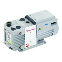
Edwards RV8 — двухступенчатый вакуумный пластинчато-роторный насос, в котором для уплотнения между элементами в рабочей камере используется вакуумное масло. Насос предназначен для откачки парогазовой смеси из вакуумных объёмов. Откачной механизм приводится в действие напрямую одно- или трёхфазным электродвигателем через гибкую муфту. Вторая ступень и маслянное уплотнение зазора позволяет значительно повысить компрессию и снизить эффект перетекания газа во внутренних зазорах рабочей камеры. Повышение компрессии приводит к снижению предельного остаточного давления в диапазоне 10-4 — 10-3 мбар.
В универсальном пластинчато-роторном насосе Edwards RV8 предусмотрены два переключателя режима работы: переключатель газобалласта и переключатель рабочих режимов откачиваемого потока. Для постоянной откачки большего потока газа и корректной работы насос нужно переключить в соответствующий режим тем самым увеличив смазку высоковакуумной ступени насоса и избежав масляное голодание. В случае работы насоса в режиме
предельного вакуума требуется переключить насос в соответствующий режим со сниженным потоком масла из-за эффекта дегазации масла в рабочей камере. Наличие быстродействующего обратного клапана с гидравлическим приводом позволяет избежать попадания масла в вакуумную систему при неправильной эксплуатации пластинчато-роторного насоса или аварийных ситуациях. На сегодняшний день пластинчато-роторные насосы Edwards серии RV стали отраслевым стандартом для научного и промышленного применения.
Преимущества вакуумных насосов Edwards RV8:
— Низкий уровень шума;
— Два режима работы – режим высокого вакуума и режим высокой производительности;
— Встроенное газобалластное устройство;
— Быстродействующий обратный клапан;
— Две модификации насоса – с однофазным или трёхфазным двигателем;
— Простота ремонта и обслуживания;
— Высокий предельный вакуум;
— Наличие большого количества дополнительных аксессуаров.
Области применения вакуумных насосов Edwards RV8:
— Аналитическое оборудование;
— Центрифуги;
— Нанесение покрытий;
— Процессы дегазации;
— Дистилляция, экстракция, фильтрация;
— Форвакуумная откачка турбомолекулярных насосов;
— Масспектрометрия.
Технические характеристики вакуумного насоса Edwards RV8:
Макс. скорость откачки при 50 Гц, м³/ч (л/мин): 8,5 (2,4)
Предельный вакуум в режиме высокого вакуума:
— без газобалласта, мбар (Торр): 2×10⁻³ (1,5×10⁻³)
— с газобалластом в положении I – малый поток, мбар (Торр): 3×10⁻² (2,3×10⁻²)
— с газобалластом в положении II – большой поток, мбар (Торр): 6×10⁻² (4,5×10⁻²)
Предельный вакуум в режиме высокой производительности:
— без газобалласта, мбар (Торр): 3×10⁻² (2,3×10⁻²)
— с газобалластом в положении I – малый поток, мбар (Торр): 4×10⁻² (3×10⁻²)
— с газобалластом в положении II – большой поток, мбар (Торр): 6×10⁻² (4,5×10⁻²)
Входное соединение: фланец NW25
Выходное соединение: фланец NW25
Максимально допустимое давление на выходе, бар: 1,2
Максимально допустимое давление на входе (с газобаластом), бар: 1,5
Максимально допустимое давление паров воды на входе, мбар (Торр): 38 (28,5)
Максимальная скорость откачки паров воды
— газобалласт – малый поток, г/ч: 60
— газобалласт – большой поток, г/ч: 220
Мощность двигателя при 50 Гц, Вт: 450
Электропитание: однофазное 115/230 В, 50/60 Гц
Диапазон рабочих температур, °C: 12 — 40
Вес насоса без масла, кг: 28
Уровень шума, дБ(А): 48
Объём масла (макс./мин.), л: 0,75/0,45
Рекомендуемое масло (в поставке): Ultragrade 19
-
Добавить к сравнению

-
Форвакуумная ловушка Edwards FL20K для вакуумных насосов
- A13305000
Edwards
шт Цена по запросу
-
-
Добавить к сравнению

-
Входная ловушка паров Edwards ITO20K для вакуумных насосов
- A44110000
Edwards
шт Цена по запросу
-
-
Добавить к сравнению

-
Входной фильтр пыли Edwards ITF20K для вакуумных насосов
- A44215000
Edwards
шт Цена по запросу
-
-
Добавить к сравнению

-
Входная химическая ловушка Edwards ITC20K для вакуумных насосов
- A44410000
Edwards
шт Цена по запросу
-
-
Добавить к сравнению

-
Входная ловушка с осушителем Edwards ITD20K для вакуумных насосов
- A44510000
Edwards
шт Цена по запросу
-
-
Добавить к сравнению

-
Фильтр масляного тумана Edwards EMF10, NW25
- A46226000
Edwards
шт Цена по запросу
-
-
Добавить к сравнению

-
Масловозвратный набор Edwards для чистых процессов для вакуумных насосов серии RV
- A50419000
Edwards
шт Цена по запросу
-
-
Добавить к сравнению

-
Адаптер газобалласта Edwards
- A50502000
Edwards
шт Цена по запросу
-
-
Добавить к сравнению

-
Набор для упрощенного слива масла Edwards для вакуумных насосов серии RV
- A50503000
Edwards
шт Цена по запросу
-
-
Добавить к сравнению

-
Сетевой кабель Edwards с вилкой (евро), 10 А
- A50506000
Edwards
шт Цена по запросу
-
-
Добавить к сравнению

-
Сетевой кабель Edwards без вилки
- A50508000
Edwards
шт Цена по запросу
-
-
Добавить к сравнению

-
Выхлопной штуцер Edwards для вакуумных насосов
- A50509000
Edwards
шт Цена по запросу
-
-
Добавить к сравнению

-
Газобалластное и масловозвратное устройство Edwards для вакуумных насосов серии RV
- A50523000
Edwards
шт Цена по запросу
-
-
Добавить к сравнению
-
Фильтрующий элемент Edwards для фильтра масляного тумана EMF10
- А22304198
Edwards
шт Цена по запросу
-
Вакуумный насос Edwards RV8 – полное описание модели
Основные характеристики: мощность 0,45 кВт, предельное остаточное давление до 0.002 мбар, максимальная производительность 8,5 м³/ч, страна производитель — Великобритания.
Промышленный пластинчато-роторный вакуумный насос Edwards RV8 в наличии! Цены, характеристики и отзывы на Edwards RV8. В наличии разнообразный модельный ряд вакуумной техники Edwards под любые запросы. Надёжность, качество оборудования подтверждаются официальной гарантией 1 год. Доставкой нашего оборудования по России и СНГ занимаются надежные перевозчики.
Посмотрите похожие подборки оборудования
Характеристики Edwards RV8
Мощность электродвигателя
0,45 кВт
Предельное остаточное давление
0.002 мбар
Максимальная производительность
8,5 м3/ч
Категория
Вакуумный насос
Частота вращения
1470 об/мин
Доставка по Москве
3 дня при заказе до 12 ч.
Гарантия 1 год
Гарантия по договору
Дилерские цены
Напрямую с завода
Информация о стоимости и сроках доставки
Доставка по Москве
| Стоимость доставки | Срок доставки | При заказе до |
|---|---|---|
| Бесплатно | 3 дн. | до 12 ч. |
Доставка по России и в отдаленные регионы
| Стоимость доставки | Срок доставки | При заказе до |
|---|---|---|
| Бесплатно | 14 дн. | до 12 ч. |
![]()
Способы оплаты:
- Оплата по счету(с НДС) согласно договору;
- Оплата картой/наличными по договору.
Мы сотрудничаем только с такими проверенными транспортными компаниями, как:
- «Деловые линии»;
- «Желдорэкспедиция»;
- «Байкал-Сервис».
Координируем и контролируем передвижение груза на всем пути следования, предоставляем пакет сопровождающих документов.
Вопросы и отзывы

Вопросы и отзывы
edwards rv8 service manual
LINK 1 ENTER SITE >>> Download PDF
LINK 2 ENTER SITE >>> Download PDF
File Name:edwards rv8 service manual.pdf
Size: 2576 KB
Type: PDF, ePub, eBook
Category: Book
Uploaded: 22 May 2019, 19:41 PM
Rating: 4.6/5 from 782 votes.
Status: AVAILABLE
Last checked: 4 Minutes ago!
In order to read or download edwards rv8 service manual ebook, you need to create a FREE account.
Download Now!
eBook includes PDF, ePub and Kindle version
✔ Register a free 1 month Trial Account.
✔ Download as many books as you like (Personal use)
✔ Cancel the membership at any time if not satisfied.
✔ Join Over 80000 Happy Readers
edwards rv8 service manualYou must use your pump as specified in this manual.Read this manual before you install and operate your pump. Important safety information is highlighted as WARNING and CAUTION instructions; you must obey these instructions.All rights reserved.Refer to Figure1 for item numbers in brackets in the following descriptions. The RV pumps are two-stage, oil-sealed, sliding-vane vacuum pumps. The pump has NW25 inlet (4) and outlet (7) ports, a gas-ballast control (5) and a mode selector (11). When the pump is switched off, an inlet-valve seals the inlet and prevents the suck-back of air and oil into the vacuum system.The RV3 and RV5 pumps. The pump-body and oil-box are made from cast-aluminium. All surfaces of the pump which are exposed to the pumped gases. All rights reserved.Edwards and the Edwards logo are trade marks of Edwards Limited.These performance characteristics are listed fully in Tables3 and4.Table5 gives the ultimate vacuum and maximum water vapour inlet pressure for each of the six possible combinations of control positions. The curves0, I, andII in Figure2 show the relationship between inlet pressure and pumping speed for High Vacuum mode Figure 2 — Performance characteristics. All rights reserved.Edwards and the Edwards logo are trade marks of Edwards Limited.PFPE-prepared pumps are suitable for oxygen applications: refer to Section8. You must ensure that the RV pump is suitable for your application. If you have any doubt as to the suitability of the RV pump for your application, refer to the Edwards guidelines on vacuum pump and vacuum system safety (see the Associated publications at the end of the Contents list at the front of this manual).A suitably trained and supervised technician must install your RV pump. Obey the safety instructions listed. If the pump is damaged, notify your supplier and the carrier in writing within three days; state the Item Number of the pump together with your order number and your supplier?s invoice number.http://edgewatercolonynj.com/userfiles/d-tamcn-characteristics-manual.xml
- Tags:
- edwards rv8 service manual, edwards rv8 service manual, edwards rv8 service manual transmission, edwards rv8 service manual transfer switch, edwards rv8 service manual pdf, edwards rv8 service manual user, edwards rv8 service manual.
Retain all the packing materials for inspection. Do not use the pump if it is damaged.If the pump. Refer to Figure4 for the item numbers in brackets.Ensure that the voltage shown on the voltage indicator (4) in the motor-cover corresponds with your electrical supply voltage. If it does not, you must change the configuration of the pump-motor to match your electrical supply voltage; use the procedure below.1.Undo the. Prices are indicative only and may vary by country, with changes to the cost of raw materials and exchange rates. Why am I doing this. I was pulling trace solvent out of a powder and at some point over night it decided to travel up the hose, through my Schlenk line, through the solvent trap and into the pump. Gunking up EVERYTHING. It had begun making a loud chuffing and stuttering, which had me worried it had seized or was going to seize at any point. Some warnings: -You are at your own risk doing this. I am in no way responsible for any damage that may occur from your following my instructions. I am just posting this up for people who want to see how it is done. I am in no way AT ALL an expert at this. Just someone who is a bit handy. -Remember, the oil in this pump will contain traces of whatever was being vacuumed down. This means it may contain solvents, toxic metals, acids, fluorinated compounds (which can break down into HF), etc. They could break your toes, hand, fingers etc.Remember most of the stuff you will be touching will be covered in pump oil. -Please dispose of pump oil properly. Mine goes with other organic wastes. If you don’t have access to this contact your local authorities on how to properly dispose of the waste. Don’t put it down the drain or just in the trash. Lastly, I will be the first to admit I am not the greatest author in the world. If anything in this ‘able needs clarification or you have suggestions for improvement feel free to mention it. Add Tip Ask Question Comment Download Step 1: Why Do Pumps Seize?http://asv-receptions.com/www/upload/d-tek-leak-detector-manual.xml You can see they move in two directions, first they move around the rotary chamber and second they move in and out of the rotating spindle. In the RV8 there is no spring in the middle, they are solid against each other, which means they have no play in their travel. As they rotate, the pressure of the walls against the vane pushes the vane into the spindle, which then pushes the other one out. Also, note on top there is a backflow preventing valve. If your pump is rotating just fine but for one reason or another isn’t getting a vacuum it could be either the vanes have failed and aren’t holding a pressure or this back flow valve is stuck open allowing oil to enter the chamber. When the vane hits the wall it can’t move into the spindle, essentially freezing the spindle in place. 3) The vanes can catastrophically fail and jam themselves up with their own pieces. Add Tip Ask Question Comment Download Step 2: Required Equipment The tools needed for this task are not overly complex or hard to fine. Many are improvised at will with what you have around. 1) Something to drain the oil into. I used a beaker but anything should work. It is a very simple aspect that makes disassembly a breeze. 3) Needle nose pliers — for helping remove bolts which have been unscrewed but need a bit of help being pulled out of their hole. 4) A flat head screw driver. This is mainly for gently prying joints apart. So plastic will actually work better but I didn’t have one so I was just careful. 5) Forceps — For scraping away debris and getting paper towels into tight places. 6) Needles or picks or something to scrape out tight places. I had a variety of metal needles on hand (sharp ones) so I used those. 7) Some sort of flat device for scraping. Being a chemist I used a chemist spatula, which worked perfectly for scraping.  Edwards Grade 19 Pump Oil (enough to drain and fill ATLEAST once to get rid of free debris.http://ninethreefox.com/?q=node/14011 I used chloroform because I have large amounts of it at my disposal, it dissolves the oil well enough and dries rapidly (you don’t want any solvent in your oil). A more commonly used solvent is hexanes, it dries just as rapidly and is more non-polar so it dissolves the oil better. Just make sure all of the parts are well dried before putting everything back together. 12) A place that you can get really oily and messy and then clean up. There is no way around it with this process. Oil is going to get EVERYWHERE. I can’t emphasize that enough. I did this in my fume hood and on my chemistry lab bench (the one exposed to chemicals). Optional: A rebuild kit. If you need to replace the vanes or seals a rebuild kit is your best option. Add Tip Ask Question Comment Download Step 3: Dissassembly (part 1) UNPLUG THE PUMP! You do not want it turning on at ANY point during this procedure. PERIOD! Just unplug it and set the cable to the side. Now, drain the oil by opening the oil refill holes and the oil drain plug. Make sure you have your collection container underneath the plug before opening it; the oil will shoot out of there. If you don’t know where the parts I am talking about are located, mouse over the squares on the first image to find these parts. Drain the oil completely (you will likely need to prop the pump up at an angle for a bit to let it fully drain). Now to remove the front cover, it is quite easy. See those four bolts on the sides (two per side). Their location is highlighted in the first image, while the second image shows a close up of these two bolts. Remove these four bolts and the cover will just come off. Depending on the condition of the insides, the cover may just come off or you may have to wiggle it to get it off. While doing this you can also remove the front level window for cleaning. Set it to the side in a safe place (it is glass). You will also see a gasket between the two metal parts, note its orientation for replacing it later.https://jagatex.pl/images/casablanca-intellitouch-manual.pdf If the gasket it is in bad shape it may require a replacement. Add Tip Ask Question Comment Download Step 4: Dissassembly (part 2) Alright, now that we have the cover off you will see a long round cylinder (the pump body) with two bolts in it and a large cap on top with one bolt in it, shown in the first image. This cap covers covers the back flow prevention valve. The air exits here so this will likely be dirty and need cleaning.Remove the bolt in this large cap and set the cap to the side. With the cap removed, you will see the back flow prevention valve (see Image 2). It consists of a footplate with some reed valves underneath. The footplate is held down by one bolt. Remove this bolt as well. Set all of this to the side for cleaning as well. Now returning to the cylindrical pump body. Remove the 2 bolts indicated in picture 3. Now depending on how dirty or what not your oil pump is, the 2nd stage may just fall off, or it may take some work. In my case even though it was dirty as heck it just came off. If it requires some work, looking at the cylinder you will see three seams in the cylinder. These are actually the separate sections. The first appears and closest to the bolts appears to be the oil pump. The second, getting farther away is the 2nd stage of the pump, and the third is the first stage of the pump. Now pry off the cover over the oil pump by inserting a flat head screwdriver in the first seam (the one closest to the bolts you just removed) and carefully working it open by gently forcing it at different points around the circumference. The cover should come off and you will be faced with the oil pump as shown in picture 4. Picture 5 shows a closeup of this. You can see it is a tiny rotary vane pump, with a solid single vane in the center. Carefully, remove the oil pump rotary spindle and then putting your screw driver in the next seam, pry the oil pump body off. As shown in picture 6. You will then have exposed the SECOND stage of the vacuum pump (it goes backwards here). Add Tip Ask Question Comment Download Step 5: Dissassembly (Part 2) Now you have the second stage of the oil pump exposed. You will notice that this section consists of a cavity with a circular metal piece in the middle with two gray plastic pieces, I call this the rotary vane assembly. Those plastic pieces are the vanes. They are VERY soft plastic, be VERY careful with them. They also are often what sticks when the pump gets seized up (either these or the ones in the first stage which we will see later). As I stated before, seizing can be caused by two different modes. The first is that the surface around the outside develops a layer of gunk which prevents these vanes from sliding along the edge and they get stuck in place. The second is that a layer of gunk develops between these vanes and the channel in the center circular piece. These parts have VERY tight tolerances and a gunk build up in there prevents the vanes from moving, sticking them in place, so that when they hit the wall and are supposed to contract in they don’t. This can actually cause vanes to shatter, which will require a rebuild kit. You will notice there are two bolts in the wall, these hold the second stage onto the first stage. Remove these and pry off the second stage, just as you did the other two seams. Note, that there is a little cylindrical adapter with groves in it which transfers motion from the rotary vanes in stage 1 to those in stage 2. Depending on where it wants to stick, it can either stick to the rotary vane in stage 1 or to the back of the rotary vane in stage 2. Don’t loose this piece, so make sure you locate it before preceding. We now have exposed everything we needed to for cleaning out the pump. Now lets test the first stage, with a pair of pliers, rotate the first stage, it should rotate relatively easily. If it seems to stick anywhere, note it for cleaning and testing. Also, check the vanes, make sure they are coming in and out as they should. If the rotor sticks at a place, it could be because the vane won’t move in any more. This would require removing this stage (which I don’t discuss). Once you know that it rotates just fine, time to clean. I just used a paper towel and solvent to fully clean the insides of this stage. It cleaned quite easily (albeit was a bit difficult for my large fingers). Scrape off any major stuck on gunk and in general make sure that it is perfectly clean paying attention to holes, flanges, the sectiongs that join to stage 2, etc. Make sure to clean this little dark metal thing up here. It is related to the gas ballast area (which helps get rid of water). This was quite clogged on mine. It took a needle and a lot of work to get it clean. Scrape the whole pump resevoir area around the first stage. Make sure it is nice and clean with as little dirt or dust leftover as possible. It takes a bit of work and a lot of scraping but remember the area around this is part of the oil reservoir and as such your oil is basically going to be sitting in contact with this almost constantly. So the cleaner the better. Once this stage is clean, time to move on to the second stage, which in my case was the problematic one. Add Tip Ask Question Comment Download Step 7: Cleaning the Pump (Second Stage) First thing is lets get the rotary vane assembly out of the second stage (if it hasn’t come out on its own). Turn the first stage over in your hand, with your fingers supporting the rotary vane assembly. Push your thumb through the hole on the backside, forcing the rotary vane assembly out. Remove the rotary vane assembly. Be careful, remember everything is oily. You don’t want to drop this. Now it is time to focus on the rotary assembly. Remove the vanes from the rotor VERY VERY carefully. If you damage them, you need to buy new ones. They have very tight tolerances. It took me a LOT of work to get these out without damaging them. A lot of careful prying with small allen wrenches, some 8G needles, etc. Good luck. Now that we have these parts free, we can clean them. Use a nail, needle, etc.When finished the rotor should be perfectly clean. Now to clean the vanes. Scrape them clean with a flat object (like a small screw driver), using a small needle to get in the fine places. You want these things PERFECTLY clean if you can. Remember any gunk could make them stick and seize up. There will likely be on the wide sides as well as the small sides so don’t skip any area. Now clean the body of the second stage just like you did with the rotor. This part took me 30-45 minutes to clean right. There was stuck on gunk EVERYWHERE. Make sure you get all of the ridges and places where the various sections join with each other. Don’t forget to clean your bolts and the piece that goes between stage 1 and 2 and connects the rotors. Add Tip Ask Question Comment Download Step 8: Cleaning the Pump (Oil Pump and the Rest) Now lets move on to the oil pump. Just like stage 2, it has a small rotary vane assembly in the center (though in this one the vanes are all one piece) with a piece that links this rotary assembly to the previous stage. Press it out just like before and begin cleaning. Once again scraping and making sure you have cleaned everything all of the holes, grooves etc. This was pretty easy for me, much more easy than stage 2. Clean and scrape out the cap and back-flow preventer parts. Clean and scrape out the outside body of the pump basically the oil reservoir, including the oil level window. This took about 1hr for me. It was honestly, quite disgusting. Add Tip Ask Question Comment Download Step 9: Reassembly Now that we have cleaned everything to our standards. Time to reassemble the pump. To reassemble first put that metal piece that connects the stage 1 rotor to stage 2. Put the Stage 2 pump body, making sure to align the screw holes. Screw stage 2 into place. Insert the stage 2 rotor. Insert the vanes (the angled corner goes inside and towards the middle). Now this next part gets tricky You need to put the oil pump on but it doesn’t have screw to hold it in place. So you have to line up the notches on the oil pump rotor assembly with those on the stage 2 rotor. Attach the oil pump lining up the screw holes and while holding the oil pump in one hand attach the oil pump cover, lining up the screw holes. Then while still holding all of this with one hand, screw in one of the screws to hold it in place. Screw in the other screw, the pump body is back together. Now reattach the backflow preventer valve. It goes on like shown. Now reattach the housing that goes on top of the backflow preventer valve. Lastly, reattach the pump body. Don’t forget the gasket that goes in between the two parts. Add Tip Ask Question Comment Download Step 10: Finished. Now we are done. It is time to flush the pump with some oil. Fill the pump with 0.75L of pump oil. Run it for aroudn 30sec-1min. This should sweep up any free debris. Drain the pump oil and refill again. Run the pump again this time listening for any weird sounds. Check and make sure the pump is pulling a good vacuum and you are finished. All that is left is to clean up your area. Good luck with things and if you have any questions feel free to ask them here. Add Tip Ask Question Comment Download Share it with us! I Made It! Recommendations How to Build the Easiest Dining Room Chair Ever Thanks, There is so little info out there, your write up is one of a couple which are very useful to overhauling a vane vacuum pump. I just overhauled an Edwards E2M12 and will post an instructable in the near future. Thanks again The first time I did the brakes on my car I felt similarly intimidated.Worked very well for RV12. Definitely just forcing them to spin helps a lot as well. 0 sofia.ferreira Do you have any suggestion as to why that happens? Thank you. Great write-up. Very helpful. I am just using this now after getting the clean and overhaul kit. I have a question — if this thread hasn’t gone extinct — the rotor is very difficult to turn once I put the 2nd stage on. After the pump portion is assembled and attached to the aluminum adaptor I need to use a wrench to make it turn. This doesn’t seem right. I am going to pull it apart again, make sure everything is lubed but am not sure what to do next. Thanks for any comments. Dan 0 pgoetz51 I will join the chorus on the shrinking intimidation factor. Also there is purpose made flushing oil available, although flushing with regular oil seems to work fine too. www.duniwaystockroom.com 0 adampinder89 I’ve just gutted and cleaned an Edwards E2M8 and an Edwards RV8, and this really helped me. These exploded diagrams are really useful when reassembling your pump, especially if you forget how everything fits together (like when your department catches fire and you can’t get back to work for a while). Again, thanks for the help. 0 pcmeiners Anyway I posted my write up of the overhaul at the following link. The original overhaul was not my pump. Obtained another for myself from the same source. Rebuilt it yesterday but it does not produce a decent vacuum. Looks like someone decided to removing scoring in the HV stage stator, using a lathe (vs a mill), as the HV stator walls seem rough, and one area has an slight indentation, just noticeable. Can’t win them all. 0 pcmeiners Also it took some time to find a pictorial parts list for the pump; for me that is a necessity in taking on any machine overhaul. 0 aong4 I have an RV12. This guide was very useful! I posted this just in case someone ended up needing to tear one down. To be honest, I was quite intimidated the first time I took one of these apart (even though I had take apart several Welch pumps before). By the end I was surprised how easy it was. Other than cleaning up all that dang oil. Post Comment Categories Circuits. Requisitos de seguranca. Bombas de vacuo Regras de seguranca para aparelhos electricos de medicao, de controlo e de laboratorio. Requisitos gerais Maquinas electricas rotativas. Canadian Standards Authority e Underwriters Laboratory. A Directiva RoHS nao e legalmente aplicavel a equipamento industrial de vacuo ate Julho de 2019 (Julho de 2017 para instrumentos). 22.08.2013, Burgess Hill Peter Meares GV Technical Support Manager Data e local Este produto foi fabricado nos termos de um sistema de qualidade com a certificacao ISO9001:2008 Modelo do documento: 02B01010 Anexo 4 Ed. 1 P200-00-551 Edicao G Nota: Esta declaracao abrange todos os numeros de serie de produtos a partir da data de assinatura desta declaracao. Todos os direitos reservados. Edwards e o logotipo da Edwards sao marcas registadas da Edwards Limited. A652-01-891 Edicao V Indice Ilustracoes Figura 1 2 3 4 5 6 7 8 9 10 11 Pagina A bomba RV. 3 Caracteristicas de funcionamento em modo Vacuo Elevado (velocidade de bombeamento vs. Pagina iii A652-01-891 Edicao V Esta pagina foi deixada em banco intencionalmente. A652-01-891 Edicao V Introducao 1.1 Ambito e definicoes Este manual fornece instrucoes de instalacao, funcionamento e manutencao para as bombas de palhetas rotativas Edwards RV3, RV5, RV8 e RV12. A bomba deve ser utilizada conforme especificado neste manual. Leia este manual antes de instalar e trabalhar com a bomba. As informacoes de seguranca importantes estao destacadas como AVISO e ADVERTENCIA; estas instrucoes devem ser cumpridas. A utilizacao de AVISOS e ADVERTENCIAS esta definida abaixo. Aviso Os avisos acontecem quando o nao cumprimento de uma instrucao pode resultar em lesoes ou na morte de pessoas. ADVERTENCIA As advertencias acontecem quando o nao cumprimento de uma instrucao pode resultar em danos no equipamento, em equipamento associado e no processo. As unidades usadas neste manual estao em conformidade com o sistema internacional de unidades de medida SI. Nao foi atribuida uma Categoria ATEX relativamente a fontes potenciais de ignicao no exterior do equipamento, dado que o equipamento nao foi concebido para utilizacao em locais onde se verifique uma atmosfera externa potencialmente explosiva. Nao existe nenhuma potencial fonte de ignicao no interior da bomba durante o funcionamento normal, mas poderao existir potenciais fontes de ignicao em situacoes previstas e raras de avaria, conforme definido na Directiva. Por conseguinte, ainda que a bomba tenha sido concebida para bombear materiais e misturas inflamaveis, os procedimentos de funcionamento deverao garantir que, em todas as condicoes normais e razoavelmente previstas, estes materiais e misturas nao estao dentro de limites de explosao. A Categoria 3 e considerada adequada para evitar a ignicao em caso de avaria rara que permita a passagem pela bomba de materiais e misturas inflamaveis dentro dos respectivos limites de explosao.Para mais informacoes, contacte a Edwards: consulte a pagina Moradas no final deste manual para obter mais detalhes. Apoios de borracha (4) 11. Selector de modo 12. Cobertura da ventoinha do motor 14. Pagina 3 A652-01-891 Edicao V Introducao 1.3 Descricao A bomba de palhetas rotativas RV da Edwards e apresentada na Figura 1. Consulte a Figura 1 para ver os numeros dos itens entre parenteses nas seguintes descricoes. As bombas RV sao bifasicas, seladas a oleo e de vacuo com palhetas deslizantes. A bomba tem portas NW25 de entrada (4) e saida (7), um controlo de lastro de gas (5) e um selector de modo (11). Quando a bomba esta desligada, uma valvula de entrada veda a entrada e impede o fluxo inverso de ar e oleo para o sistema de vacuo. As bombas RV3 e RV5 tem uma pega retractil (3). As bombas RV8 e RV12 tem um suporte de transporte para utilizar com equipamento de elevacao adequado. Uma bomba de oleo envia oleo pressurizado para o mecanismo de bombeamento a vacuo da bomba RV. A condicao e o nivel do oleo podem ser observados na caixa de oleo atraves do vidro de observacao (8). A caixa de oleo tem dois tampoes de enchimento de oleo (6) e um tampao de drenagem de oleo (9). O mecanismo da bomba e accionado directamente por um motor electrico monofasico ou trifasico atraves de um acoplamento de motor flexivel. O motor esta totalmente fechado, sendo arrefecido pela ventoinha de arrefecimento do motor, que encaminha o ar ao longo das pas do motor. As bombas sao arrefecidas por uma ventoinha adicional ligada ao acoplamento do motor. Quando o motor esta muito quente, o dispositivo de sobrecarga termica desliga a bomba. O dispositivo de sobrecarga termica tem uma reactivacao automatica; quando o motor arrefece, o dispositivo e reactivado e (excepto se tiver sido incorporado um equipamento de controlo adequado que deva ser activado manualmente: consulte a Seccao 3.7.2 e a Seccao 3.8.2), o motor sera reiniciado. A partir do final de 2009, foram colocados motores melhorados nas bombas RV. Estes motores beneficiam de uma instalacao com uma caixa de terminais em aluminio e com comutadores de tensao acessiveis a partir do exterior. A introducao destes motores resultou numa gama de motores que abrange todas as tensoes e na reducao de condicoes de frequencia de quatro variantes para duas. Todos os motores sao intermutaveis e o rendimento da bomba nao e afectado. O bomba esta montada numa base sobre apoios de borracha (10). Pode encontrar detalhes sobre isoladores de vibracoes e outros acessorios adequados na Seccao 7. Consulte a Seccao 8 para obter informacoes adicionais se a bomba estiver preparada para PFPE. 1.4 Controlos e modos de funcionamento A bomba tem dois controlos: o selector de modo (11) e o controlo de lastro de gas (5). Seis combinacoes possiveis destes controlos permitem uma ampla variedade de caracteristicas de funcionamento para optimizar o funcionamento da bomba para uma aplicacao especifica. 1.4.1 Selector de modo O selector de modo tem duas posicoes; consulte a Seccao 4.2 para seleccionar estas posicoes. Durante o restante manual, sera utilizada a seguinte convencao: z O modo Vacuo Elevado e especificado pelo simbolo 6. z O modo Rendimento Elevado e especificado pelo simbolo 6. Com o selector de modo na posicao Vacuo Elevado 6, o oleo pressurizado e conduzido apenas para a fase de vacuo reduzido. Neste modo de funcionamento, a bomba proporciona o vacuo maximo melhor possivel. Com o selector de modo na posicao Rendimento Elevado 6, o oleo pressurizado e conduzido para as fases de vacuo elevado e vacuo reduzido. Neste modo de funcionamento, a bomba consegue suportar pressoes de entrada elevadas por muito tempo. A652-01-891 Edicao V Controlo de lastro de gas Para bombear cargas de vapor elevadas, e introduzido na bomba lastro de gas para evitar que os gases bombeados transportem condensacao de vapor. Pode ser introduzido ar na fase de vacuo reduzido atraves da valvula de lastro de gas. Como alternativa, pode ser fornecido atraves de uma valvula externa adequada um gas inerte como o azoto. O corpo da bomba e a caixa de oleo sao em aluminio fundido. Todas as superficies da bomba expostas a gases bombeados estao isentas de cobre, zinco e cadmio. Pagina 5 Introducao 1.4.2 A652-01-891 Edicao V Esta pagina foi deixada em banco intencionalmente. As posicoes do selector de modo e do controlo de lastro de gas definem as caracteristicas de funcionamento da bomba. Estas caracteristicas de funcionamento estao listadas na integra na Tabela 3 e na Tabela 4. A Tabela 5 apresenta o vacuo maximo e a pressao maxima de entrada de vapor de agua de cada uma das seis combinacoes possiveis de posicoes dos controlos. As curvas 0, I e II da Figura 2 mostram a relacao entre a pressao de entrada e a velocidade de bombeamento em modo Vacuo Elevado 6 Figura 2 — Caracteristicas de funcionamento em modo Vacuo Elevado (velocidade de bombeamento vs. Medida na porta de entrada para ISO 2372 (1974) 2.5 Nota: Dados de lubrificacao As fichas de dados de seguranca da Edwards para oleos de bombas rotativas estao disponiveis a pedido. Pagina 13 A652-01-891 Edicao V Dados tecnicos 2.6 Nota: Dados electricos: bombas monofasicas A Edwards recomenda a utilizacao de fusiveis com as potencias maximas especificadas na Tabela 9 e na Tabela 10. Nao devem ser utilizados fusiveis com uma potencia mais elevada. O motor de dupla tensao e dupla frequencia foi concebido para uma fonte de alimentacao electrica monofasica, sendo adequado para funcionamento a 50 Hz ou 60 Hz. O motor pode ser ligado manualmente entre tensoes de alimentacao nominais de 110 a 120 V e 220 a 240 V (consulte a Seccao 3.7.1). Quando e iniciada uma bomba a frio, o motor usara a corrente de arranque apresentada na Tabela 9 e na Tabela 10 ate varios segundos, pelo que deve ser utilizado um fusivel “lento” para evitar falhas de fusiveis desnecessarias durante o arranque da bomba. Apos cinco minutos, a medida que o oleo na bomba aquece, a corrente utilizada baixara lentamente para a corrente a plena carga especificada na Tabela 9 e na Tabela 10. A652-01-891 Edicao V Dados electricos: bombas trifasicas O motor de dupla tensao e dupla frequencia foi concebido para uma fonte de alimentacao electrica trifasica, sendo adequado para funcionamento a 50 Hz ou 60 Hz. O motor pode ser ligado manualmente entre tensoes de alimentacao nominais de 220 a 240 V e 380 a 460 V (consulte a Seccao 3.8.1). As bombas sao fornecidas preparadas de origem para alimentacoes electricas nominais de 380 a 460 V. Quando e iniciada uma bomba a frio, o motor usara a corrente de arranque apresentada na Tabela 11 ate 0,5 segundos.
![]()
![]()
![]()
Вернуться назад
Edwards
| Артикул | Цена, руб. | Наличие на складе | Количество | ||||
|---|---|---|---|---|---|---|---|
| A65401903 |
|
Под заказ |
Описание
Оплата и доставка
Серия двухступенчатых пластинчато-роторных насос RV это вакуумные насосы, в которых для уплотнения между элементами в рабочей камере используется масло. Насосы предназначены для откачки парогазовой смеси из вакуумных объёмов.
- Двухступенчатый вакуумный насос со скользящими пластинами и масляным уплотнением;
- два режима управления: с помощью газобалластного устройства и переключателя рабочих режимов:
- режим «Высокий вакуум» — при нем создается наименьшее предельное давление;
- режим «Высокая производительность» — при нем обеспечивается длительная работа насоса при высоком входном давлении;
- встроенное газобалластное устройство препятствует конденсации откачиваемых паров внутри насоса;
- шесть возможных комбинаций положения газобалласта и переключателя рабочих режимов позволяют получить широкий набор рабочих характеристик;
- наличие быстродействующего обратного клапана позволяет избежать попадания масла в вакуумную систему при неправильной эксплуатации пластинчато-роторного насоса;
- две модификации насоса — с однофазным (представлены на сайте) или трёхфазным (по запросу) двигателем через муфту;
- скорость откачки:
- для 50 Гц, м³/ч — 8,5;
- для 60 Гц, м³/ч — 10,0;
- максимальное давление на входе (с газобалластом), изб.атм. — 0,5;
- максимальное давление на выходе, изб.атм. — 1;
- предельное давление вакуума без газобалласта, мбар — 2,0×10⁻³;
- предельное давление вакуума с газобалластом (положение I/II), мбар — 3,0×10⁻²/6,0×10⁻¹;
- максимальное давление для паров воды на входе, мбар — 60;
- максимальная скорость откачки паров воды, кг/ч — 0,06-0,22;
- возможность вручную переключение двигателя между напряжение 110-120 В и 220-240 В;
- габариты, мм — 470 × 158 × 225;
- масса, кг — 28.
Комплект поставки: насос вакуумный, 1 л масло Ultragrade 19, входной фильтр и уплотнительное кольцо.
Доставка по Москве
Доставка осуществляется по всей России и странам СНГ. Возможен самовывоз со склада по адресу Московская область, г. Мытищи, 7-й Ленинский переулок, д.13. Доставка по Москве и Московской области осуществляется бесплатно.
Цена товара указана со склада в Москве и не включает расходы на доставку в другие города.
Вы можете выбрать способ доставки в личном кабинете, чтобы он автоматически указывался при оформлении всех последующих заказов. При выборе варианта «Транспортная компания по выбору клиента» укажите в комментариях транспортную компанию, с которой вы предпочитаете работать.
Точная стоимость доставки рассчитывается менеджером при подтверждении заказа в зависимости от весообъемных характеристик и дальности. Товары, требующие особого температурного режима, доставляются с соблюдением требуемых условий. Если в заказе есть прекурсоры, необходимо оформить официальное письмо об отпуске прекурсоров. (образец письма об отпуске прекурсоров)
Оплата
Компания Диаэм работает с юридическими и физическими лицами. После оформления заказа продавец-консультант сформирует счет и направит его вам по электронной почте и на страницу заказа в Личном кабинете на сайте. Вы также можете сами сформировать счет из Корзины, авторизовавшись на сайте. Счет оплачивается через банк. Вы можете оплатить товар в кассе Диаэм или любом отделении банка.
Для получения товара необходимо предоставление доверенности организации, а для получения товара при оплате физическим лицом необходим паспорт.

Аксессуары

H11025015
Масло для вакуумного насоса Ultragrade 19, 1 л
11 400 руб.
A50506000-EU
Кабель питания Pump Line Cord Set N Europe (IEC320 C13)
3 455 руб.
A44215000
Входной фильтр пыли ITF20K
222 178 руб.
Фильтр масляного тумана EMF10
А50502000
Переходник RV для газобалласта
По запросу
А50509000
Адаптер выхлопной для присоединения гибкого шланга 3/4
1 343 руб.
А65401130
Набор лопаток
По запросу
А65499000
Двигатель, для RV8, RV12, однофазный
1 руб.
A65401032
Картридж
По запросу
Похожие товары
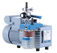
20698029
Насос пластинчато-роторный, до 0,002 мбар, 2,3 м³/ч, в комплекте фильтр и заслонка, RZ 2.5
По запросу
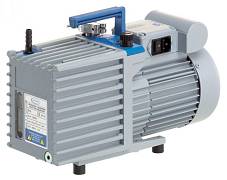
20698130
Насос пластинчато-роторный, до 0,002 мбар, 5,7 м³/ч RZ 6, в комплекте фильтр и заслонка
По запросу
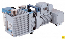
20698560
Насос пластинчато-роторный-мембранный, до 0,002 мбар, 5,9 м³/ч, химически-стойкий, RC 6
853 758 руб.
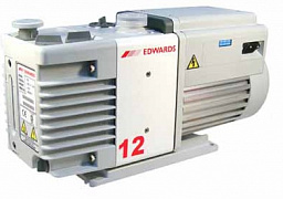
A65501903
Насос пластинчато-роторный, до 0,002 мбар, 12 м³/ч, 1-фазный, RV12
583 664 руб.
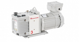
A65201903
Насос пластинчато-роторный, до 0,002 мбар, 3,3 м³/ч, 1-фазный, RV3
445 327 руб.
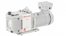
A65301903
Насос пластинчато-роторный, до 0,002 мбар, 5,1 м³/ч, 1-фазный, RV5
459 445 руб.