Page 1
CMS3CMS 600-3 COMPACT MIXING SYSTEMOwner‘s Manual | Bedienungsanleitung
Page 2
CMS3102.2 Input StereoSince most features – AUX/MON controls and channel faders – of the STEREO INPUTS are virtually identical to the ones of the MONO
Page 3 — CONTENTS
CMS311achieved at the 0 dB mark. The control offers level reduction of -10 dB and an amplification of +20 dB. This range allows the connection of most
Page 5 — 1 Introduction
CMS313The two effect programs are equally suitable for live performance or recording applications and can be used separately or together. For testing,
Page 7
CMS3152.4 AUXGenerally, the AUX channel is used for the connection of an additional, external FX unit. Depending on the setting of the AUX 1/2 POST bu
Page 9 — NDICATOR
CMS31738 — MASTER LED-DISPLAYThe CMS offers two 10-segment LED-chains for optical monitoring the output levels of the L/R master signals. The indi-cat
Page 11
CMS31947 — PHONESThis control sets the volume of the headphones connected.CAUTION: Make sure to set the control to its minimum position before connect
Page 13 — FFEKT RETURN FADER
CMS320Menu modePress the MENU/ENTER rotary encoder in effect mode to enter the menu mode. In menu mode the display indicates the function being execut
Page 14
CMS3213 Display & functionsThe CMS includes a premium OLED display. Compared to general LC displays the OLED display is brighter, has a greater c
Page 15 — 2.6 MASTER with GEQ
CMS322MENU STRUCTUREEDIT FX 1 / FX 2This dialog allows editing effect parameters for effect unit FX 1 or FX 2. The available parameters will vary de-p
Page 16
CMS323This dialog is used to change the user preset‘s descrip-tion. Turn the MENU/ENTER rotary encoder to the left or right to edit the highlighted ch
Page 17 — OF MASTER B
CMS324Turn the MENU/ENTER rotary encoder to highlight an en-try in the left column of the FX Control Setup dialog. Press the MENU/ENTER rotary encoder
Page 18
CMS325ed, pressing the MENU/ENTER rotary encoder resets the CMS to its factory settings. If NO has been selected, all parameters stay unchanged and th
Page 19
CMS3264 DIGITAL AUDIO INTERFACEThe USB 2.0-Port of the CMS serves as digital audio inter-face for the connection of a PC or Apple Macintosh (Mac). Th
Page 20 — 2.8 Rear panel
CMS3274.3 Status displayIn effect mode, the display of the CMS shows the status information of the DIGITAL AUDIO INTERFACE.4.4 PC-MIDI-InterfaceThe CM
Page 21 — 3 Display & functions
CMS3284.6 Example of usage (Recording)In the following application, your PC/Mac is used for recording while the CMS functions as premium A/D con-verte
Page 22 — Set FX Name
CMS3295 Setting up a standard PA5.1 CablingThe mains supply cord comes with the CMS. The quality of all other cables lies in your responsibility. Car
Page 23 — FX Control Setup
CMS33CONTENTSINTRODUCTION . . . . . . . . . . . . . . . . . . . . . . . . . . . . . . . . 5Scope of Delivery, Unpacking and Inspection . . . 5Wa
Page 24 — Device Setup
CMS330between the two speaker “clusters” – the more compact the sound.4. Try to avoid the positioning of the main loudspeak-ers behind the imaginary l
Page 25 — 3.3 Effects
CMS331MONITOR MIX1. Set the MON fader located in the master section to the -5 dB mark.2. Set the MON controls of all input channels accord-ing to your
Page 26 — 4 DIGITAL AUDIO INTERFACE
CMS3326 Setup examples6.1 CMS with D-Lite activeoneIllustration 6-1: CMS with D-Lite activeone (2 x D 8A, 1 x PowerSub 212) as main PA, 1 x D 8A used
Page 27
CMS3336.2 CMS with D-Lite activetwoIllustration 6-2: CMS with D-Lite activetwo (2 x D 8A + 2 x PowerSub 112) as main PA, 1 x D 8A used as monitor
Page 28 — LIVE-RECORDING OF EVENTS
CMS3346.3 CMS with D-Lite activefourIllustration 6-3: CMS with D-Lite activefour (2 x D 11A + 2 x PowerSub 212) as main PA, 1 x D 11A used as monitor
Page 29 — 5 Setting up a standard PA
CMS3356.4 CMS with Xa-2 systemIllustration 6-4: CMS with Xa-2 system (2 x FX 12, 4 x FX20, 2 x Xa 4000) as main PA, 1 x D 8A used as monitorXa 4000Xa
Page 30 — 5.3 Soundcheck
CMS3366.5 CMS with CORUS-Evolution systemIllustration 6-5: CMS with CORUS-Evolution system (2 x C 25.2, 2 x Sub 2.18, 2 x LX 3000, 1 x DSP 260) as mai
Page 32 — 6 Setup examples
CMS338WICHTIGE SICHERHEITSHINWEISE1. Lesen Sie diese Hinweise.2. Heben Sie diese Hinweise auf.3. Beachten Sie alle Warnungen.4. Richten Sie sich nach
Page 34
CMS34IMPORTANT SAFETY INSTRUCTIONS1. Read these instructions.2. Keep these instructions.3. Heed all warnings.4. Follow all instructions.5. Do not use
Page 35 — 6.4 CMS with Xa-2 system
CMS3402 Bedienelemente und Anschlüsse2.1 Input MonoHINWEIS: Achten Sie bitte darauf, dass vor dem Anschluss von Signalquellen die jeweiligen Kanalreg
Page 36 — LX 3000 LX 3000
CMS341HINWEIS: Betreiben Sie bitte keine E-Gitarre bzw. E-Bass mit passiver Elektronik und hochohmigem Ausgang direkt an einem Mischpult LINE-Eingang.
Page 37
CMS3425 — KLANGREGELUNG (HI-, MID-, LO-REGLER)Die Klangregelung erlaubt eine sehr umfangreiche und effektive Beeinflussung des Eingangssignals innerha
Page 38 — WICHTIGE SERVICEHINWEISE
CMS3439 — PAN-REGLERDieser Regler bestimmt die räumliche Position des Eingangssignals im Stereobild. In Mittelstellung wird das Signal zu gleichen Tei
Page 39 — 1 Einführung
CMS3442.2 Input StereoViele Funktionsgruppen wie AUX-Regler, MON-Regler und Fader sind im Stereo-Eingang identisch zum Mono-Eingang aufgebaut und wurd
Page 40 — 2.1 Input Mono
CMS34515 — TRIM LINE CD-REGLERMit diesem Regler wird das Signal an den Klinken-Eingängen bzw. Cinch-Eingängen im Stereokanal an den internen Ar-beitsp
Page 41 — Z-SCHALTER
CMS3462.3 FX 1/2Das CMS ist mit zwei unabhängig regelbaren 24bit-Stereo-Effektteilen FX 1 und FX 2 ausgestattet. Die beiden Effektteile sind völlig id
Page 42
CMS3472. Mit der DOWN-Taste (links) schalten Sie die Presets in absteigender Reihenfolge durch, mit der UP-Taste (rechts) in aufsteigender Reihenfolge
Page 44
CMS3492.4 AUXDer Kanalzug AUX kann beliebig zum Monitoring oder als FX Send (bei Wahl von AUX POST) betrieben werden. Zusätz-lich ist AUX auf dem Aufn
Page 45
CMS351 IntroductionBecause of its comprehensive set of integrated features – like equalizer and effects units – the Compact Mixing System DYNACORD CM
Page 47
CMS35138 — MASTER-AUSSTEUERUNGSANZEIGEDie Aussteuerungsanzeige des CMS besteht aus zwei LED-Ketten für den rechten bzw. linken Kanal mit je 10 LEDs pr
Page 49 — 2.6 MASTER mit GEQ
CMS35346 — PHONES-BUCHSEDiese Stereo-Klinkenbuchse (6,3 mm) ist für Kopfhörer von 32 bis 600 Ohm geeignet. Hier kann das PFL-Signal abgehört werden, w
Page 50
CMS3542.7 DISPLAY mit Funktions-Tasten52 — DISPLAY MIT 4 FUNKTIONSTASTENZum Schutz vor Verkratzen ist das Displayglas bei Auslieferung mit einer Folie
Page 51
CMS35556 — NETZSCHALTER (POWER)Netzschalter zum Ein- und Ausschalten des Gerätes. Das Gerät ist betriebsbereit, wenn das Display aufleuchtet. Achten S
Page 52
CMS3563 Display & FunktionenDas CMS ist mit einem hochwertigen OLED-Display ausgestattet. Im Vergleich zu üblichen LC-Displays sind OLED-Dis-play
Page 53
CMS357MENÜ-BAUMEDIT FX1/FX2 MENUDieser Dialog erlaubt es, bestimmte Parameter des im Effektteil FX 1 bzw. FX 2 gewählten Effekts zu editieren. Die zur
Page 54 — 2.8 Rückseite
CMS358Im Set FX Name Dialog kann die Bezeichung des User Presets eingegeben werden. Drehen Sie den MENU/EN-TER-Drehencoder nach links oder rechts, um
Page 55 — ETZSCHALTER (POWER)
CMS359Im FX Control Setup Dialog kann durch Drehen des MENU/ENTER-Drehencoders ein Eintrag in der linken Spalte markiert und durch Drücken des MENU/EN
Page 56 — 3 Display & Funktionen
CMS362 Controls, Indicators and Connections2.1 Input MonoHINT: When connecting signal sources, please make sure to set the corresponding channel fade
Page 57
CMS360Play 11-12 at STDBYUm im STANDBY-Betrieb des CMS über den Eingang 11-12 (bzw. CD 3-4) Hintergrundmusik einspielen zu können, wählen Sie hier den
Page 58
CMS3614 DIGITAL AUDIO INTERFACEDie USB 2.0-Schnittstelle dient als digitale Audio-Schnitt-stelle des CMS für einen PC oder Mac. Das DIGITAL AU-DIO IN
Page 59 — Display Brightness 100%
CMS3624.3 Funktionsanzeige im DisplayDas Display des CMS zeigt in der Effekt-Betriebsart Sta-tusinformationen des DIGITAL AUDIO INTERFACE an.4.4 PC-MI
Page 60 — 3.3 Effekte
CMS363HINWEIS: Sollen MIDI-Daten mit der Medienwiedergabe von Windows an externen Geräten wiedergegeben wer-den, müssen Sie in der Windows-Systemsteue
Page 61
CMS364E-Gitarre) nur gering oder gar nicht auf die Beschallungs-anlage gegeben werden. Umgekehrt klingen Aufnahmen, die nur über ein Raummikrofon gema
Page 62
CMS3655 Aufbau einer Standard-PA5.1 VerkabelungDas Netzkabel haben Sie mit dem CMS erhalten. Für alle anderen Kabel sind Sie selbst verantwortlich un
Page 64 — CMS 1000-3)
CMS367Kanälen nur bei sehr hohen Dynamikspitzen auf-leuchtet. Bei häufigem Aufleuchten drehen Sie die FX-Regler in allen beteiligten Eingangskanälen i
Page 65 — 5 Aufbau einer Standard-PA
CMS3686 Aufbaubeispiele6.1 CMS mit D-Lite activeoneAbbildung 6-1: CMS mit D-Lite activeone (2 x D 8A, 1 x PowerSub 212) als Haupt-PA, zusätzlich 1 x
Page 66
CMS3696.2 CMS mit D-Lite activetwoAbbildung 6-2: CMS mit D-Lite activetwo (2 x D 8A + 2 x PowerSub 112) als Haupt-PA, zusätzlich 1 x D 8A für den Moni
Page 67 — ETZTE KORREKTUREN
CMS37HINT: Please, do not connect E-guitars or E-basses with passive, high impedance outputs directly to a LINE input. The LINE inputs of the CMS – li
Page 68 — 6 Aufbaubeispiele
CMS3706.3 CMS mit D-Lite activefourAbbildung 6-3: CMS mit D-Lite activefour (2 x D 11A + 2 x PowerSub 212) als Haupt-PA, zusätzlich 1 x D 11A für den
Page 71 — 6.4 CMS mit Xa-2 System
CMS3737 SpecificationsProperty CMS 600-3Order No. F01U213891DC-CMS600-3-UNIVChannels 4 +2 + 2 MIC/Line-Mono 4 MIC/Line-Mono / USB-Stereo (Super C
Page 72
CMS374Device in rated condition, unity gain (MIC gain 20 dB), all faders position 0 dB, all pots in mid position, master fader +6 dB, unless otherwise
Page 75 — 7.1 Dimensions
CMS377Trademarks. • Microsoft, Windows, Windows XP, Windows Vista and Windows 7 are either registered trademarks or trademarks of Microsoft Corporatio
Page 78
CMS38sound. You should use the natural reproduction as an orientation mark and rely on your musically trained ear. The moderate use of the MID control
Page 79
DYNACORD12000 Portland Avenue South, Burnsville, MN 55337, USA Europe, Africa, and Mid
Page 80 — DYNACORD
CMS3911 — PFLEngaging the PFL button routes the audio signal to the headphones bus, so that it is present at the phones output con-nector. The meter i
![]()
Mixer & Powermixer
MIXING CONSOLES AND POWERED MIXERS
Mobile Audio | Concert Sound | Fixed Installation | Pro Entertainment
English

PRODUCTS
|
PowerMate3 |
04 — 27 |
|
CMS3 |
28 — 43 |
TECHNICAL SPECIFICATIONS
|
PowerMate3 |
44 — 45 |
|
CMS3 |
46 — 47 |

Perfection. Passion. PowerMate
PowerMate3
·· PowerMate 600-3 ·· PowerMate 1000-3 ·· PowerMate 1600-3 ·· PowerMate 2200-3

PowerMate 2
Innovation as
Tradition
 DYNACORD can draw upon a 65-year tradition in the development and manufacture of mobile mixing amplifiers.
Its first innovatory step was the integration of signal mixing and power amplification with compact, portable devices; this was soon followed by models that brought echo and reverberation on board. DYNACORD can therefore be considered the ‘inventor’ of the power mixer. To this day, nothing in the fundamental concept has changed, though, of course, ever since the PowerMate was first introduced, all the functional units have conformed to the highest professional standards. Never has there been the faintest suspicion of a compromise-based ‘cheap solution’. Quite the reverse, in fact.
MORE POWER • MORE EFFECTS • MORE EXTRAS was the watchword of the developers of the ‘original’ PowerMate, and their exemplary realization of these aims set a new standard in mixing desks with integrated effects units and power amplifiers. In the PowerMate, the professional user has a mixing desk, multi-effects unit and power amplifier that is capable of delivering concert sound performance, that is compact and portable but nonetheless a very powerful system solution, and that as a small-PA leaves nothing to be desired.
The same spirit of innovation has dominated the further development of what was already an exquisite piece of technology and finds expression in a wealth of technical details, in its user-friendliness, its reliability and safety of operation, its efficient energy management and its superb styling. The perfection of every component reflects the passion of the developers.
PERFECTION. PASSION. POWERMATE.
Third-generation success story: the PowerMate3
THE CURRENT POWERMATE GENERATION FEATURES A MULTITUDE OF INNOVATIONS AND OPTIMIZATIONS. DESPITE A CLEAR REDUCTION IN WEIGHT, IT OFFERS CONSIDERABLE GAINS IN TERMS OF BOTH POWER AMPLIFIER OUTPUT AND FEATURES, AS WELL AS BEING MORE COMPACT THAN EVER BEFORE.
|
PowerMate 600-3 |
PowerMate 600-3 |
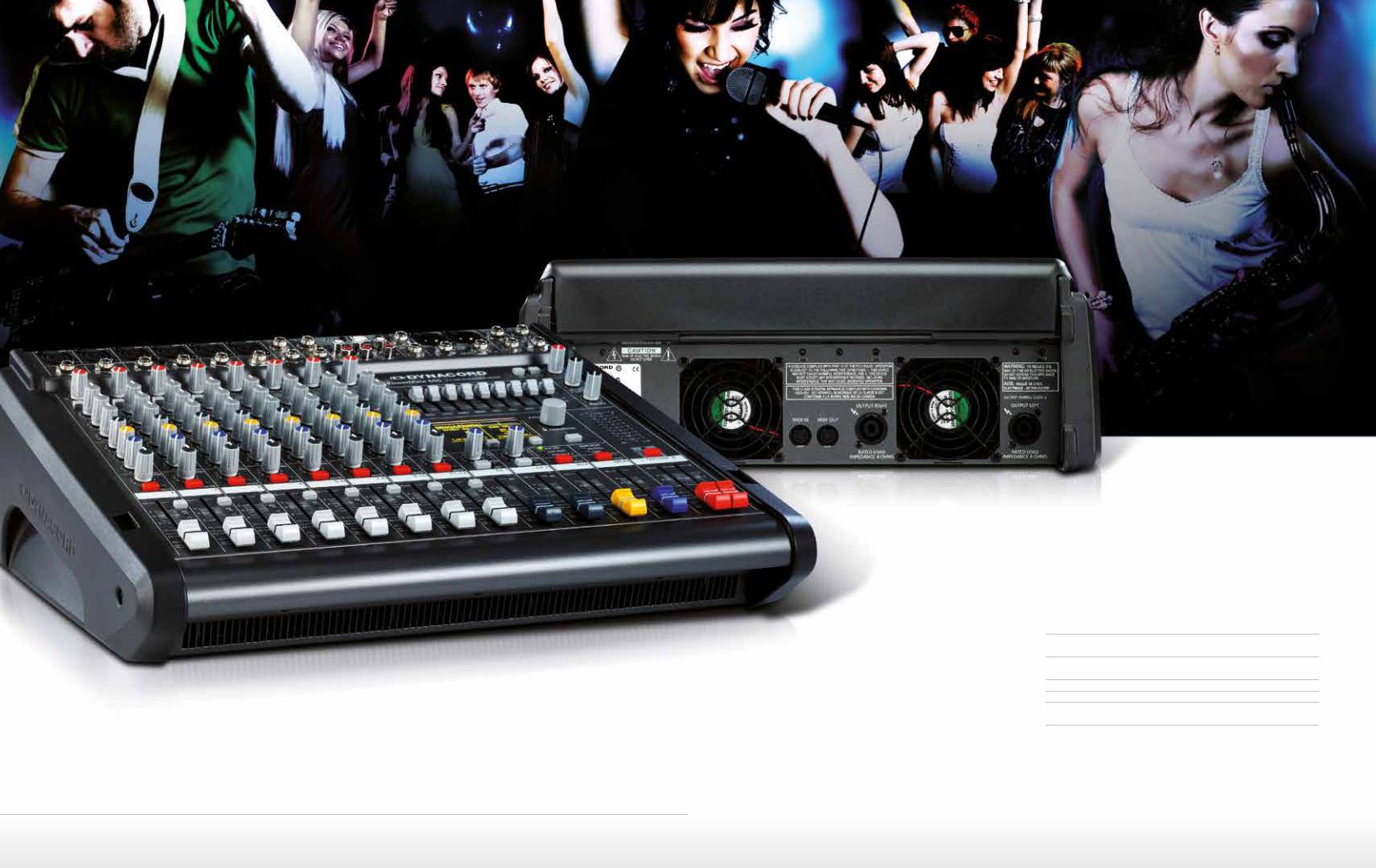
PowerMate 600-3
THIS EXTREMELY COMPACT POWERED MIXER IS THE YOUNGEST MEMBER OF THE POWERMATE3 FAMILY.
 With a total output of 2,000 watts, it is far and away the most powerful compact mixer on the world market, yet it weighs only 9kg!
With its very lavish feature set and exemplary versatility it is the ideal choice for all professional applications in which few channels yet very high audio quality are required.
PERFORMANCE WITHOUT COMPROMISES
•Intuitively operated mixing section
•2 editable digital effects devices with 100 presets each and 20 user memories each
•Professional 4xIN / 4xOUT digital interface (USB) for the connection of a PC or Mac
•Stereo equalizer in the master section
•Large, contrast-rich OLED display
•class-D high-performance power amplifier delivering 2 x 1,000 watts RMS into 4 ohms
Exclusively high-quality brand components have been used; all faders and potentiometers are supplied by ALPS.

PowerMate 600-3
IN THE MIXER SECTION, A TOTAL OF 8 CHANNEL STRIPS ARE AVAILABLE
•4 MIC / LINE channels
•2 MIC / Stereo USB channels (‚Super Channels‘)
•2 stereo LINE channels
MIC / LINE
 The MIC / LINE channels offer extremely low-noise and low-hum electronically balanced XLR microphone inputs with an extremely low distortion factor (typ. < 0.002%) for the connection of low-impedance microphones.
For condenser microphones, phantom power (+48 volts) is centrally switchable. The LINE inputs are also electronically balanced and implemented as jack
sockets. In addition to a GAIN control, a highly efficient 3-band equalizer, an FX send, an AUX send and a MONitor send as well as either Panorama or Balance controls are available. The four MIC / LINE channels boast, in addition, a switchable 80Hz Lo-Cut filter, whilst the Super Channels 5-6 and 7-8 are supplied by the USB inserts 1-2 and 3-4, in each case in stereo.
STEREO-LINE
The STEREO-LINE channels (9-10 and 11-12) offer electronically balanced jack inputs for the connection of electronic instruments such as keyboards, drumcomputers, guitars and basses with active electronics, as well as all other high-level stereo signal sources such as additional mixers, effects devices etc.
CD or MP3 players can be connected to the additional cinch (RCA) inputs CD 1-2 and CD 3-4, which are switched in parallel. The tone controls and sends are identical to those of the MIC / LINE channels.
In all input channels, a Signal / Peak LED is provided to assist level control. The SIG LED illuminates at
around 30 dB and the PK LED at 6dB beneath the distortion threshold. A MUTE button and a PFL button (in channels 5-12 in stereo) are further features found in all input channels.
PowerMate 600-3

|
PowerMate 600-3 |
PowerMate 600-3 |
DIGITAL AUDIO INTERFACE
 The DIGITAL AUDIO INTERFACE supplies two stereo channels, present as USB 1-2 and USB 3-4 in Super Channels 5-6 and 7-8 respectively.
This interface is implemented professionally in 24-bit resolution and supports sampling rates up to 96 kHz, thereby satisfying studio requirements. The USB sends are supplied with the Master L and R, AUX and MON signals. The DIGITAL AUDIO INTERFACE can be used for input and output simultaneously.
Via the USB 2.0 port of your PC / Mac, four channels can be transmitted simultaneously in each direction. When a USB 1.1 interface is used, two channels can be transmitted simultaneously in each direction.
The PowerMate is designed for the level of standard PCs / Macs; the gain level can easily be adjusted, if need be, from the computer connected.
Included in the delivery is a DVD containing the professional recording software Cubase LE and PC / Mac USB drivers.
PC-MIDI-INTERFACE
The PowerMate also makes available a fully-featured PC MIDI interface.
The MIDI input also supports the remote switching of both internal effects units using a master keyboard or MIDI footswitch.
MASTER-SECTION
In the PowerMate‘s Master Section are to be found the Master A L+R sends (on separate faders), an additional Master B send (switchable pre/post and mono/stereo), the stereo effects returns, and the send signals of the AUXiliary and MONitor busses. If the AUX buss is not used to supply FX 2, it can be switched pre or post and thereby used as an additional monitor send or to supply an external effects device.
The 9-band stereo equalizer in the master section allows you to adjust the frequency response to the acoustics of the room.
The REC SEND and USB OUT controls determine the level of the master L+R signal at the Rec Send sockets and in the output channels of the digital USB interface. The control below it allows you to adjust the volume
in the headphones. Two ten-LED meters provide an overview of the power amplifier level. When the PFL switch is activated, the left-hand LED chain shows the internal level of the master buss in dBu.
STANDBY
The STANDBY switch mutes all outputs. For the playback of things like interval music, the DEVICE SETUP menu allows you to route stereo channel 11-12 for standby operation directly to the power amplifiers.

|
PowerMate 600-3 |
PowerMate 600-3 |
THE POWERMATE IS EQUIPPED WITH TWO VERY HIGH-QUALITY, 24-BIT STEREO EFFECTS PROCESSORS, FX 1 AND FX 2
 These function independently and can therefore be mixed. The two effects units are fully identical in design. Each effects section offers 100 presets including high-quality reverb, delay and modulation effects selected by means of the display.
When a delay effect is active, the delay time can be synchronized to the beat of the music using the TAP key. The further possibility exists of modifying individual parameters of the presets and storing the results in the 20 each user memories provided.
Both effects units are supplied by the FX Send buss. Using the DEVICE SETUP menu, you can, if you wish, configure the AUX send buss to function as an FX 2 send, so that only the FX 1 effects unit is supplied by the FX 1 buss. In this way, the two effects devices can be controlled independently of one another.
The effects can be mixed separately in the master and monitor busses.
The large, high-contrast OLED display is easily read from a wide range of viewing angles—even in very bright surroundings. The operation of the effects units and
processing menus is intuitive and made easier still through the use of soft keys and a rotary
encoder.
|
DEVICE SETUP |
LPN-PROCESSING |
SPEAKER PROTECTION |
PROCESSING-MENUS
Particularly valuable in making it possible to adjust the PowerMate perfectly to the selected loudspeaker cabinets, thereby optimizing the audio performance and maximizing the operating safety and reliability of the system, are the LPN Processing and Speaker Protection menus.
LPN-PROCESSING
Typical small to medium-sized loudspeaker cabinets, for physical reasons that have nothing to do with their make or quality, exhibit distortion in the transient response of the woofer. Since neither graphic nor parametric equalizers can do anything to alleviate this problem, the PowerMate offers a configurable LPN (low-pass notch) filter. Depending upon the size of the loudspeaker cabinet being used and also to adjust to problematic acoustics (such as those of bassy,
boom-ridden rooms), the LPN filter can be set to either High or Medium. The result is considerably greater punch (e.g. from the bass drum), an extension downwards of the frequency response, and improved transparency in the bass and midrange.
SPEAKER PROTECTION
This menu allows you to match perfectly the continuous power output of the PowerMate’s power amplifiers to the connected loudspeakers in the interests of greater operational safety and reliability.
Through dynamic limiting of the maximum power at the output, loudspeaker damage due to thermal overload can be avoided, without the wide dynamic range of the power amplifiers being sacrificed. For this purpose, the maximum permissible nominal
power handling of the connected loudspeaker cabinet can be selected from the menu. Unlike the case with conventional voltage limiters, dynamic peaks of short duration are permitted, as loudspeaker cabinets can as a rule tolerate peak levels many times higher than their nominal sustainable loads (RMS).
The speaker protection supervises permanently the amount of energy being fed to the loudspeakers, only limiting it in the event of a threatened overload, and even then, doing
so softly and inaudibly. For peak levels of short duration, the full output of the power amplifier remains available at all times, even when relatively small cabinets are being used. As a result, not only is the maximum dynamic range of the system maintained but also, and at all times, the highest degree of operational safety and reliability.
 Loading…
инструкцияDynacord CMS 600-3

CMS
3
CMS 600-3 COMPACT MIXING SYSTEM
Owner‘s Manual | Bedienungsanleitung
Посмотреть инструкция для Dynacord CMS 600-3 бесплатно. Руководство относится к категории смесители, 8 человек(а) дали ему среднюю оценку 8.1. Руководство доступно на следующих языках: английский. У вас есть вопрос о Dynacord CMS 600-3 или вам нужна помощь? Задайте свой вопрос здесь
- 1 Introduction
- 2 Controls, Indicators and Connections
- 3 Display & functions
- 4 DIGITAL AUDIO INTERFACE
- 5 Setting up a standard PA
- 6 Setup examples
- 1 Einführung
- 2 Bedienelemente und Anschlüsse
- 3 Display & Funktionen
- 4 DIGITAL AUDIO INTERFACE
- 5 Aufbau einer Standard-PA
- 6 Aufbaubeispiele
- 7 Specifications
Главная
| Dynacord | |
| CMS 600-3 | DYNACORD CMS 600-3 | |
| смеситель | |
| английский | |
| Руководство пользователя (PDF), Техническая спецификация (PDF) |
Аудио
| Количество каналов | 8 канала |
| Цифровая обработка звука | 24 бит |
| Фейдер канала (1 кГц) | 85 dB |
| Интервал выборки | 96 kHz |
| Диапазон частот | 15 — 70000 Hz |
Выходные соединения
| Суммарный коэффициент гармоник (THD) | 0.005 % |
Порты и интерфейсы
| Количество портов USB 2.0 | 1 |
| MIDI выход | Да |
| Вход Aux | Да |
Экран
Технические характеристики
| DJ микшер | — |
| Монтаж в стойку | Да |
| Цвет товара | Черный |
| Функция видео | — |
Вес и размеры
| Ширина | 416.9 mm |
| Глубина | 347.8 mm |
| Высота | 108.6 mm |
| Вес | 5800 g |
| Масса брутто | 7800 g |
Энергопитание
| Потребляемая мощность (в обычном режиме) | 35 W |
Эквалайзер
показать больше
Не можете найти ответ на свой вопрос в руководстве? Вы можете найти ответ на свой вопрос ниже, в разделе часто задаваемых вопросов о Dynacord CMS 600-3.
Какой вес Dynacord CMS 600-3?
Dynacord CMS 600-3 имеет вес 5800 g.
Как лучше всего выполнять чистку смеситель?
Для удаления отпечатков пальцев лучше всего использовать слегка влажную салфетку для уборки или мягкую чистую ткань. Пыль в труднодоступных местах лучше всего удаляется потоком сжатого воздуха.
Какая высота Dynacord CMS 600-3?
Dynacord CMS 600-3 имеет высоту 108.6 mm.
Какая ширина Dynacord CMS 600-3?
Dynacord CMS 600-3 имеет ширину 416.9 mm.
Какая толщина Dynacord CMS 600-3?
Dynacord CMS 600-3 имеет толщину 347.8 mm.
Инструкция Dynacord CMS 600-3 доступно в русский?
К сожалению, у нас нет руководства для Dynacord CMS 600-3, доступного в русский. Это руководство доступно в английский.
Не нашли свой вопрос? Задайте свой вопрос здесь
Руководстве по эксплуатации Dynacord CMS 600-3 — вам приходилось его терять? Поскольку вы попали сюда, наверняка с вами это случилось. Но вы не единственный человек, сталкивающийся с проблемами с хранением руководства по эксплуатации всех домашних устройств. Ниже несколько советов, касающихся того, зачем собирать руководства по эксплуатации.
Руководстве по эксплуатации Dynacord CMS 600-3 это определенный вид технической документации, являющейся неразлучным элементом каждого устройства, которое мы приобретаем. Они отличаются между собой количеством информации, которую можно найти на тему данного устройства: напр. Dynacord CMS 600-3. Конечно же, если производитель считает что необходимо передать нам большее количество информации, касающейся устройства Dynacord CMS 600-3, то стоит ее хоть раз прочитать — в начале, сразу же после покупки данной вещи. Однако мы считаем, что инструкции должны заключать самую важную, наиболее необходимую информацию о Dynacord CMS 600-3, так, чтобы не отнимать желания пользователя прочесть ее уже в самом начале. Несомненно, если устройство Dynacord CMS 600-3 имеет много продвинутых функций, неизбежно большое количество информации в содержании этого документа.
Które из информации в инструкции Dynacord CMS 600-3 необходимо обязательно прочитать?
- Информацию, касающуюся правильного использования и ухода за устройством Dynacord CMS 600-3 — нам необходимо ознакомиться с основными правилами, чтобы в случае проблем с устройством сервисный центр не отказал нам в гарантийном обслуживании, из-за неправильного использования
- Информация, касающаяся самых частых проблем с Dynacord CMS 600-3 и способы их решения
- Информация, касающаяся гарантии устройства Dynacord CMS 600-3 и ближайших сервисных центров, способных починить устройство в соответствии с рекомендациям производителя Dynacord
Как хранить инструкции дома?
Хорошей идеей является предназначение одного ящика, в котором бы хранилась инструкция Dynacord CMS 600-3 а также всех других домашних устройств которыми мы пользуемся. Тогда значительно легче вам будет ее найти, чем искать в родных коробках, которые наверняка уже выбросили вы, или другие домочадцы. Раз в год достаточно просмотреть ящик и выбросить инструкции, которые касаются устройств, которыми вы уже не пользуетесь. Таким образом вы избежите хранения ненужных документов, а останутся только актуальные. Вы можете также скачать и распечатать инструкцию Dynacord CMS 600-3 чтобы разместить ее в своем ящике.
Похожие инструкции
 Loading…
инструкцияDynacord CMS 600-3
CMS
3
CMS 600-3 COMPACT MIXING SYSTEM
Owner‘s Manual | Bedienungsanleitung
Посмотреть инструкция для Dynacord CMS 600-3 бесплатно. Руководство относится к категории смесители, 8 человек(а) дали ему среднюю оценку 8.1. Руководство доступно на следующих языках: английский. У вас есть вопрос о Dynacord CMS 600-3 или вам нужна помощь? Задайте свой вопрос здесь
- 1 Introduction
- 2 Controls, Indicators and Connections
- 3 Display & functions
- 4 DIGITAL AUDIO INTERFACE
- 5 Setting up a standard PA
- 6 Setup examples
- 1 Einführung
- 2 Bedienelemente und Anschlüsse
- 3 Display & Funktionen
- 4 DIGITAL AUDIO INTERFACE
- 5 Aufbau einer Standard-PA
- 6 Aufbaubeispiele
- 7 Specifications
Главная
| Dynacord | |
| CMS 600-3 | DYNACORD CMS 600-3 | |
| смеситель | |
| английский | |
| Руководство пользователя (PDF), Техническая спецификация (PDF) |
Аудио
| Количество каналов | 8 канала |
| Цифровая обработка звука | 24 бит |
| Фейдер канала (1 кГц) | 85 dB |
| Интервал выборки | 96 kHz |
| Диапазон частот | 15 — 70000 Hz |
Выходные соединения
| Суммарный коэффициент гармоник (THD) | 0.005 % |
Порты и интерфейсы
| Количество портов USB 2.0 | 1 |
| MIDI выход | Да |
| Вход Aux | Да |
Экран
Технические характеристики
| DJ микшер | — |
| Монтаж в стойку | Да |
| Цвет товара | Черный |
| Функция видео | — |
Вес и размеры
| Ширина | 416.9 mm |
| Глубина | 347.8 mm |
| Высота | 108.6 mm |
| Вес | 5800 g |
| Масса брутто | 7800 g |
Энергопитание
| Потребляемая мощность (в обычном режиме) | 35 W |
Эквалайзер
показать больше
Не можете найти ответ на свой вопрос в руководстве? Вы можете найти ответ на свой вопрос ниже, в разделе часто задаваемых вопросов о Dynacord CMS 600-3.
Какой вес Dynacord CMS 600-3?
Dynacord CMS 600-3 имеет вес 5800 g.
Как лучше всего выполнять чистку смеситель?
Для удаления отпечатков пальцев лучше всего использовать слегка влажную салфетку для уборки или мягкую чистую ткань. Пыль в труднодоступных местах лучше всего удаляется потоком сжатого воздуха.
Какая высота Dynacord CMS 600-3?
Dynacord CMS 600-3 имеет высоту 108.6 mm.
Какая ширина Dynacord CMS 600-3?
Dynacord CMS 600-3 имеет ширину 416.9 mm.
Какая толщина Dynacord CMS 600-3?
Dynacord CMS 600-3 имеет толщину 347.8 mm.
Инструкция Dynacord CMS 600-3 доступно в русский?
К сожалению, у нас нет руководства для Dynacord CMS 600-3, доступного в русский. Это руководство доступно в английский.
Не нашли свой вопрос? Задайте свой вопрос здесь
Руководстве по эксплуатации Dynacord CMS 600-3 — вам приходилось его терять? Поскольку вы попали сюда, наверняка с вами это случилось. Но вы не единственный человек, сталкивающийся с проблемами с хранением руководства по эксплуатации всех домашних устройств. Ниже несколько советов, касающихся того, зачем собирать руководства по эксплуатации.
Руководстве по эксплуатации Dynacord CMS 600-3 это определенный вид технической документации, являющейся неразлучным элементом каждого устройства, которое мы приобретаем. Они отличаются между собой количеством информации, которую можно найти на тему данного устройства: напр. Dynacord CMS 600-3. Конечно же, если производитель считает что необходимо передать нам большее количество информации, касающейся устройства Dynacord CMS 600-3, то стоит ее хоть раз прочитать — в начале, сразу же после покупки данной вещи. Однако мы считаем, что инструкции должны заключать самую важную, наиболее необходимую информацию о Dynacord CMS 600-3, так, чтобы не отнимать желания пользователя прочесть ее уже в самом начале. Несомненно, если устройство Dynacord CMS 600-3 имеет много продвинутых функций, неизбежно большое количество информации в содержании этого документа.
Które из информации в инструкции Dynacord CMS 600-3 необходимо обязательно прочитать?
- Информацию, касающуюся правильного использования и ухода за устройством Dynacord CMS 600-3 — нам необходимо ознакомиться с основными правилами, чтобы в случае проблем с устройством сервисный центр не отказал нам в гарантийном обслуживании, из-за неправильного использования
- Информация, касающаяся самых частых проблем с Dynacord CMS 600-3 и способы их решения
- Информация, касающаяся гарантии устройства Dynacord CMS 600-3 и ближайших сервисных центров, способных починить устройство в соответствии с рекомендациям производителя Dynacord
Как хранить инструкции дома?
Хорошей идеей является предназначение одного ящика, в котором бы хранилась инструкция Dynacord CMS 600-3 а также всех других домашних устройств которыми мы пользуемся. Тогда значительно легче вам будет ее найти, чем искать в родных коробках, которые наверняка уже выбросили вы, или другие домочадцы. Раз в год достаточно просмотреть ящик и выбросить инструкции, которые касаются устройств, которыми вы уже не пользуетесь. Таким образом вы избежите хранения ненужных документов, а останутся только актуальные. Вы можете также скачать и распечатать инструкцию Dynacord CMS 600-3 чтобы разместить ее в своем ящике.
Похожие инструкции
CMS3 2 CMS3 CONTENTS INTRODUCTION . . . . . . . . . . . . . . . . . . . . . . . . . . . . . . . . Scope of Delivery, Unpacking and Inspection . . . Warranty . . . . . . . . . . . . . . . . . . . . . . . . . . . . . . . . Installation and Connections . . . . . . . . . . . . . . . . HF-Interference . . . . . . . . . . . . . . . . . . . . . . . . . . . CONTROLS, INDICATORS AND CONNECTIONS . . . . . . . . . . . Input Mono . . . . . . . . . . . . . . . . . . . . . . . . . . . . . . Input Stereo . . . . . . . . . . . . . . . . . . . . . . . . . . . . . FX 1/2 . . . . . . . . . . . . . . . . . . . . . . . . . . . . . . . . . . AUX . . . . . . . . . . . . . . . . . . . . . . . . . . . . . . . . . . . . MON . . . . . . . . . . . . . . . . . . . . . . . . . . . . . . . . . . . MASTER with GEQ . . . . . . . . . . . . . . . . . . . . . . . . DISPLAY with function keys . . . . . . . . . . . . . . . . . Rear panel . . . . . . . . . . . . . . . . . . . . . . . . . . . . . . . DISPLAY & FUNCTIONS . . . . . . . . . . . . . . . . . . . . . . . . . . . Effect mode . . . . . . . . . . . . . . . . . . . . . . . . . . . . . Menu mode . . . . . . . . . . . . . . . . . . . . . . . . . . . . . . Effects . . . . . . . . . . . . . . . . . . . . . . . . . . . . . . . . . . DIGITAL AUDIO INTERFACE . . . . . . . . . . . . . . . . . . . . Installing the USB driver . . . . . . . . . . . . . . . . . . . . Cubase LE . . . . . . . . . . . . . . . . . . . . . . . . . . . . . . . Status display . . . . . . . . . . . . . . . . . . . . . . . . . . . . PC-MIDI-Interface . . . . . . . . . . . . . . . . . . . . . . . . . Examples of usage (Playback) . . . . . . . . . . . . . . . Example of usage (Recording) . . . . . . . . . . . . . . . MIDI tone generator and multi-effect unit . . . . . . SETTING UP A STANDARD PA . . . . . . . . . . . . . . . . . . . . . . Cabling . . . . . . . . . . . . . . . . . . . . . . . . . . . . . . . . . Setting up . . . . . . . . . . . . . . . . . . . . . . . . . . . . . . . Soundcheck . . . . . . . . . . . . . . . . . . . . . . . . . . . . . SETUP EXAMPLES . . . . . . . . . . . . . . . . . . . . . . . . . . . . . . CMS with D-Lite activeone . . . . . . . . . . . . . . . . . . CMS with D-Lite activetwo . . . . . . . . . . . . . . . . . . CMS with D-Lite activefour . . . . . . . . . . . . . . . . . . CMS with Xa-2 system . . . . . . . . . . . . . . . . . . . . . CMS with CORUS-Evolution system . . . . . . . . . . . SPECIFICATIONS . . . . . . . . . . . . . . . . . . . . . . . . . . . . . . . Dimensions . . . . . . . . . . . . . . . . . . . . . . . . . . . . . . Block Diagram . . . . . . . . . . . . . . . . . . . . . . . . . . . . INHALT 5 5 5 5 5 6 6 10 12 15 15 15 19 20 21 21 21 25 26 26 26 27 27 27 28 28 29 29 29 30 32 32 33 34 35 36 73 75 76 39 39 39 39 40 40 44 46 49 49 49 54 54 56 56 56 60 61 61 61 62 62 63 63 64 65 65 65 66 68 68 69 70 71 72 73 75 76 3 CMS3 IMPORTANT SAFETY INSTRUCTIONS The lightning flash with arrowhead symbol, within an equilateral triangle is intended to alert the user to the presence of uninsulated „dangerous voltage“ within the product’s enclosure that may be of sufficent magnitude to constitute a risk of electric shock to persons. The exclamation point within an equilateral triangle is intended to alert the user to the presence of important operating and maintance (servicing) instructions in the literature accompanying the appliance. 1. 2. 3. 4. 5. 6. 7. 8. 9. 10. 11. 12. 13. 14. 15. 16. 17. 18. 19. Read these instructions. Keep these instructions. Heed all warnings. Follow all instructions. Do not use this apparatus near water. Clean only with a dry cloth. Do not cover any ventilation openings. Install in accordance with the manufacture’s instructions. Do not install near heat sources such as radiators, heat registers, stoves, or other apparatus (including amplifiers) that produce heat. Do not defeat the safety purpose of the polarized or the grounding-type plug. A polarized plug has two blades with one wider than the other. A grounding type plug has two blades and a third grounding prong. The wide blade or the third prong are provided for your safety. I the provided plug does not fit into your outlet, consult an electrician for replacement of the obsolete outlet. Protect the power cord from being walked on or pinched particularly at plugs, convenience receptacles, and the point where they exit from the apparatus. Only use attachments/accessories specified by the manufacturer. Use only with the cart, tripod, bracket, or table specified by the manufacturer, or sold with the apparatus. When a cart is used, use caution when moving the cart/apparatus combination to avoid injury from tip-over. Unplug this apparatus during lightning storms or when unused for a long period of time. Refer all servicing to qualified service personnel. Servicing is required when the apparatus has been damaged in any way, such as power-supply cord or plug is damaged, liquid has been spilled or orbjects have fallen into the apparatus, the apparatus has been exposed to rain or moisture, does not operate normally, or has been dropped. Do not expose this equipment to dripping or splashing and ensure that no objects filled with liquids, such as vases, are placed on the equipment. To completely disconnect this equipment from the AC Mains, disconnect the power supply cord plug from the AC receptacle. The mains plug of the power supply cord shall remain readily operable. No naked flame sources, such as lighted candles, should be placed on the apparatus. The product should be connected to a mains socket outlet with a protective earthing connection. IMPORTANT SERVICE INSTRUCTIONS CAUTION: These servicing instructions are for use by qualified personnel only. To reduce the risk of electric shock, do not perform any servicing other than that contained in the Operating Instructions unless you are qualified to do so. Refer all servicing to qualified service personnel. 1. 2. 3. 4. 5. 6. 7. 8. Security regulations as stated in the EN 60065 (VDE 0860 / IEC 65) and the CSA E65 - 94 have to be obeyed when servicing the appliance. Use of a mains separator transformer is mandatory during maintenance while the appliance is opened, needs to be operated and is connected to the mains. Switch off the power before retrofitting any extensions, changing the mains voltage or the output voltage. The minimum distance between parts carrying mains voltage and any accessible metal piece (metal enclosure), respectively between the mains poles has to be 3 mm and needs to be minded at all times. The minimum distance between parts carrying mains voltage and any switches or breakers that are not connected to the mains (secondary parts) has to be 6 mm and needs to be minded at all times. Replacing special components that are marked in the circuit diagram using the security symbol (Note) is only permissible when using original parts. Altering the circuitry without prior consent or advice is not legitimate. Any work security regulations that are applicable at the locations where the appliance is being serviced have to be strictly obeyed. This applies also to any regulations about the work place itself. All instructions concerning the handling of MOS-circuits have to be observed. NOTE: SAFETY COMPONENT (MUST BE REPLACED BY ORIGINAL PART) Due to line current harmonics, we recommend that you contact your supply authority before connection. 4 CMS3 1 Introduction Because of its comprehensive set of integrated features – like equalizer and effects units – the Compact Mixing System DYNACORD CMS 600-3 is a professional mixer offering an optimized all-in-one solution for basically any application. The CMS console is quickly set up. Complicated rack configuration and interference-prone wiring of several single components cease to apply. The mixer’s ergonomic console shape and clearly structured controls provide perfect overview for instant access at all times. Also during the transport you will quickly learn to appreciate the CMS’s superiority: compact dimensions and a very low weight. However, if you would rather like to install your CMS in a 19” rack shelf, no problem. The only thing you have to do is to replace the plastic side panels by a pair of metal rack mount ears. Through its multiple functions, its high dynamic capacity, and extremely low-noise design in combination with its 24-bit Dual-Stereo effect unit and the USB 2.0 DIGITAL AUDIO INTERFACE, the CMS is best equipped for universal use. 1.1 Scope of Delivery, Unpacking and Inspection • • • • • 1 CMS 1 Owner‘s Manual (this document) 1 Mains Cord (2 meters) 1 Warranty Certificate including Safety Instructions 1 DVD with USB driver, documentation, software,... Open the packaging and take out the CMS. Remove the FX unit display‘s protective foil. Inspect the CMS‘s enclosure for damages that might have occured during transportation. Each CMS is examined and tested in detail before leaving the manufacturing site to ensure that it arrives in perfect condition at your place. Please inform the transport company immediately if the CMS shows any damage. Being the addressee, you are the only person who can claim damages in transit. Keep the cardboard box and all packaging materials for inspection by the transport company. Keeping the cardboard box including all packing materials is also recommended, if the CMS shows no external damages. CAUTION: 1.3 Installation and Connections Do not cover the ventilation louvers in the bottom plate of the appliance. Always place the CMS on an even surface to allow for sufficient airflow during the operation. Before establishing the mains supply connection, please make sure that the device matches the voltage and frequency of your local mains supply. Check the label next to the mains switch. HINT: Using original Neutrik connectors is recommended for optimal audio quality. 1.4 HF-Interference This equipment has been tested and found to comply with the limits for a Class B digital device, pursuant to Part 15 of the FCC Rules. These limits are designed to provide reasonable protection agains harmful interference in a residential installation. This equipment generates, uses and can radiate radio frequency energy and, if not installed and used in accordance with the instructions, may cause harmful interference to radio communications. However, there is no guarantee that interference will not occur in a particular installation. If this equipment does cause harmful interference to radio or televsion reception, which can be determined by turning the equipment off and on, the user is encouraged to try to correct the interference by one or more of the following measures: • Reorient or relocate the receiving antenna • Increase the separation between the equipment and receiver • Connect the equipment into an outlet on a circuit different from that to which the receiver is connected • Consult the dealer or an experienced radio/TV technician for help Do not ship the CMS in any other than its original packaging. Packing the CMS like it was packed by the manufacturer guarantees optimum protection from transport damage. 1.2 Warranty Visit www.dynacord.com for warranty information. 5 CMS3 2 Controls, Indicators and Connections 2.1 Input Mono HINT: When connecting signal sources, please make sure to set the corresponding channel faders or at least the master faders to their minimum positions or engage the STANDBY switch. This will save you, your audience, and the equipment from extensive wear from unpleasant pops. 1 - MIC Electronically balanced XLR-type inputs for the connection of low impedance microphones like the ones featured in major studio and live mixing consoles. This type of input stage provides extraordinary low noise signal conversion at an extremely low distortion rate (typical < 0.002%) even in the high frequency range. Generally, any type of microphone can be connected as long as its pin assignment is in accordance to the diagram shown below. When condenser microphones are connected, you have to press the PHANTOM POWER button, which is located in the input section. The microphone gets its operating voltage (+48 V DC) through the mixer. PHANTOM POWER is activated/deactivated for all 6 MIC inputs together. Illustration 2-1: Microphon input The MIC input accepts levels between -60 dBu and +11 dBu – depending on the setting of the corresponding gain control. Because of the low impedance and the switchable PHANTOM POWER the XLR input is preferred for MIC applications. Because of the higher level and impedance matching the LINE input should be preferred for connecting further mixers, effect units, keyboards etc. 2 - LINE Electronically balanced inputs for the connection of electronic instruments, such as keyboards, drum machines, E-guitars and E-basses with an active output, as well as all other high level signal sources, like additional mixers, FX units, CD players, etc. The LINE input accepts levels between -40 dBu and +31 dBu. The connection of balanced or unbalanced signal sources is established through monaural or stereo phone plugs, assigned according to the diagram below. If the device that you want to connect has a balanced output stage, the use of balanced cables with stereo phone plugs is preferable. This type of connection is greatly insensitive to the induction of external noise or HF interference. Illustration 2-2: Unbalanced or balanced assignment of line input UNBALANCED COLD HOT Do not connect identical signal sources to LINE and MIC inputs at the same time, since the signals would interfere with each other, resulting in level reduction. 6 CMS3 HINT: Please, do not connect E-guitars or E-basses with passive, high impedance outputs directly to a LINE input. The LINE inputs of the CMS – like the Line level inputs of mixers from other manufacturers – are designed for the connection of the relatively low source impedance of electronic instruments. The reproduction of the instrument’s original sound characteristics will be unsatisfactory. Connect those instruments using a special transformer or pre-amplifier with very high input impedance. Musical instruments with an active electronic output (battery-powered) can be connected without any problems. 3 - GAIN CONTROL Rotary control for adjusting a MIC/LINE input’s sensitivity. These controls let you optimally adjust the incoming signals to the mixer’s internal operation level. Cautious adjusting offers the benefits of an improved S/N-ratio and provides you with the full bandwidth of the CMS’s outstanding sound capabilities. On the XLR-type connectors an amplification of 10 dB is achieved when the control is set all the way to the left and +60 dB when the control is set all the way to the right. Especially when dealing with very low input levels – during vocal recordings and when the speaker is located in a distance – the high gain is extremely profitable. Using the LINE input, the signal is generally attenuated by -20 dB while maintaining the total adjustment range of 50 dB. The LINE input’s unity gain – no amplification (0 dB) – is achieved at the 20 dB mark. The following is meant as a short note for your assistance on how to determine the right input level: GAIN setting instructions: 1. 2. 3. 4. Set the gain control and the corresponding channel fader to their minimum values. Connect the desired sound source (microphone, musical instrument, etc.) to the desired MIC or LINE input. Start the reproduction of the sound source at the highest volume level to be expected – respectively sing or speak as loud as possible directly (short distance) into the microphone. While playing the sound source or singing into the microphone, adjust the input level using the gain control, so that during the loudest passages the PK LED is just not lit, but the SIG present LED lights constantly. This is the basic channel setting, leaving you with at least 6 dB of headroom, i.e. you have at least a range of 6 dB before signal clipping occurs. In case you intend to make further adjustments to the channel’s EQ setting, you should perform steps 3. and 4. again afterwards, since changes in the sound shaping section also have an influence on the channel’s overall level. 4 - LO CUT 80 HZ When the LO CUT switch (available in channel 1 to 4) is engaged, frequencies below 80 Hz are attenuated (18 dB octave slope). In most cases using the LO CUT filter with microphone channels is a good advice, since it efficiently suppresses popping sounds, rumbling noise and low-frequency feedback. The only exceptions are kick drum and acoustic bass. Activating the LO CUT and raising the bass level (LO EQ) provides you with a richer sound, without additional rumbling or popping noise. Another welcome side effect is, that the power amplifier and the connected loudspeakers do not get “polluted” with unnecessary low-pitched interference. Your audience will be thankful for the use of the LO CUT filter, too, since in this way they can enjoy a truly clear, natural, and powerful sound performance. Illustration 2-3: LO CUT filter 5 - EQ SECTION The mixer’s EQ section allows very differentiated shaping of the incoming audio signal within miscellaneous frequency bands. Turning one of the EQ level controls to the right boosts/amplifies the corresponding frequency range while turning it to the left lowers/attenuates the signal of that specific frequency band. Before you begin to alter the sound, all EQ controls should be set to their neutral position, i.e. their marker points straight up (locked in place). Try not to set the EQ controls to extreme positions. Usually, minor changes are totally sufficient and produce the best results in the overall 7 CMS3 sound. You should use the natural reproduction as an orientation mark and rely on your musically trained ear. The moderate use of the MID control is the best remedy to avoid acoustical feedback. Especially in this frequency range you should try to avoid excessive enhancement. Lowering the level more or less in this band will provide you with high amplification rates without feedback. Use the LO control according to your pleasing, to add more “punch” to the sound of a kick drum or “body” to the vocals. Use the HI control in the same way to provide cymbals and the human voice with more treble and a more transparent sound. The MID control is active in a comparably wide frequency band around 2.4 kHz. With most microphones this is the critical range, where a slight attenuation offers excellent results. Illustration 2-4: LO/MID/HI filters 6 - FX The FX control allows adjusting individual amounts of the input signals to be routed to the integrated FX 1 and the FX 2 effects units. The signal path is split post volume fader – post fader – so that the fader setting also influences the amount of the signal that is fed to the FX units. Using the FX controls lets you easily assign an effect for groups of musical instruments or vocals. To determine the desired intensity of each effect, you should start with the control set at the center and make individual adjustments from there on. Please monitor the PK LEDs in the FX 1/2 channels. The indicator should only light briefly at the occurrence of high program peaks. If the indicator is constantly lit, you should lower the send levels of those channels where the program peaks occur. For further information, please read the paragraphs about the FX 1/2 units. 7 - AUX The AUX control is primarily meant for establishing an independent monitor mix. The AUX mix is available as output channel at the DIGITAL AUDIO INTERFACE. The AUX routing dialog in the menu allows determining whether the signals are split pre or post fader, or using the AUX as FX 2, see page 23 for details. The selected mode is indicated by LEDs, see page 15. 8 - MON The MON control is primarily meant for establishing an independent monitor mix. The signal routing is always PRE FADER. Additionally the MON channel is available at the DIGITAL AUDIO INTERFACE (channel USB 4). 9 - PAN This control determines the position of the connected sound source within the stereo image. When this control is set at its center position, the audio signal is fed with equal levels to the L and R master busses. The PAN control section is designed to maintain the essential sound pressure level, no matter at what position within the stereo image the PAN control is set to. 10 - MUTE The MUTE button mutes the input signal post fader, including all AUX/MON sends. PFL and Signal/ Peak stay functional. HINT: Use the MUTE button for muting temporarily not used input channels without changing the settings of the FX/AUX/MON controls and the channel fader. 8 CMS3 11 - PFL Engaging the PFL button routes the audio signal to the headphones bus, so that it is present at the phones output connector. The meter instrument in the master section is simultaneously switched, so that the left LED-chain indicates the level of the actually chosen channel (in dBu), which allows optimally matching the level of the signal source. The phones output volume does not dependent on the setting of the corresponding channel fader (Pre Fader Listen), which provides the possibility to listen to or shape the sound of the selected audio signal, without need to include it in the master mix. 12 - SIG / PK INDICATOR The signal-peak indicator plays a key role when setting input levels. Unlike the mixers of many other manufacturers that either only provide a peak indicator or no channel indicator at all, the PK (peak) LED of the CMS provides optical indication of the risk of occurring overdrive before you would actually hear the distortion over the connected speaker systems. As outlined in the setting instructions, the Signal-LED should blink in the rhythm of the incoming signal. If this is not the case, you have to increase the gain. If the PK LED, on the other hand, blinks frequently or lights continuously, the corresponding channel is likely to enter clipping and you have to turn the gain control a bit to the left. The SignalLED lights at levels 30 dB below clipping while the peak LED lights at a level of 6 dB below the occurrence of overdrive. Keeping an eye on the indicator during a performance is also a good idea, because some very dynamically performing members of a band or changing keyboard setups can easily lead to channel clipping, resulting in the degradation of the overall sound. 13 - FADER The channel faders set the volume of the corresponding channels, establishing an accurately proportioned mix. The channel faders should be positioned within the range of -5 dB to 0 dB, leaving you with a degree of control that allows the precise matching of relative big differences in the channels’ level settings. The overall volume is set through the use of the master faders. Even though the channel faders offer an additional amplification of +10 dB, we would like to advise you to exceed the +5 dB mark only in very few exceptional cases. If the CMS’s summing bus gets “overloaded” with too many “high level” input channels, despite its special gain structure, the summing amplifier could be driven into clipping. Once you register, that some channel faders are set above the 0 dB marking, lowering the setting of each channel fader by about -5 dB and increasing the overall output level by elevating the master faders is the wiser solution. The proportion of the mix and the overall volume stay the same while the risk of clipping is banished. 9 CMS3 2.2 Input Stereo Since most features – AUX/MON controls and channel faders – of the STEREO INPUTS are virtually identical to the ones of the MONO INPUTS we will not discuss their functioning in detail again. Thus, in the following we only point out the differences and like to ask you to refer to the analogous paragraphs within this owner’s manual describing the mono inputs. HINT: The stereo inputs 5-6 and 7-8 are designed as so-called Super Channels. This means a MIC and LINE input is available at this stereo inputs, like in the mono inputs. So, depending on the application, the Super Channels can be used for a mono signal or a stereo signal of the DIGITAL AUDIO INTERFACE (USB). 14 - STEREO INPUT L/MONO R Electronically balanced inputs for the connection of musical instruments with stereo output, like keyboards, drum machines, E-guitars and E-basses with an active output as well as all other equivalent sound sources with high level outputs, like additional mixing consoles, FX units, CD players, etc. The stereo LINE input is meant for balanced or unbalanced sound sources with levels between -20 dBu and +30 dBu. Using phone plugs For the connection of external devices to inputs 9-10 or 11-12 you can use monaural or stereo phone plugs, which are in accordance to the diagram below. If the external appliance is equipped with a balanced output stage, using balanced cables and plugs is preferable, since this type of connection provides improved shielding against HF induction and external noise. In case you want to connect a monaural sound source to a stereo input channel, you just have to plug it into the L/MONO input. The signal gets internally routed to both channels. Illustration 2-5: Unbalanced or balanced assignment of phone plus UNBALANCED COLD HOT Using RCA plugs The RCA inputs CD 1-2 and CD 3-4 are connected in parallel to the phone inputs LINE 9-10 or LINE 1112. Do not connect signal sources to phone and RCA inputs at the same time. Illustration 2-6: RCA inputs CD 1-2 and 3-4 Using the DIGITAL AUDIO INTERFACE (USB) When using the DIGITAL AUDIO INTERFACE two stereo signals are available at USB 1-2 (input 5-6) or USB 3-4 (input 7-8). Do not connect signal sources to the MIC or LINE of this stereo inputs when using the DIGITAL AUDIO INTERFACE for playback. See page 15 for more details about the DIGITAL AUDIO INTERFACE. Illustration 2-7: DIGITAL AUDIO INTERFACE DIGITAL AUDIO INTERFACE 15 - TRIM LINE CD These rotary controls are for matching the incoming line level signals (phone or RCA) to the operating level of the CMS. The total adjustment range is 30 dB. Unity gain – no amplification (0 dB) – is 10 CMS3 achieved at the 0 dB mark. The control offers level reduction of -10 dB and an amplification of +20 dB. This range allows the connection of most professional, semi professional, and hi-fi sound sources. For further details on how to set the TRIM LINE CD control, please refer to the description of the GAIN control in monaural channels. 16 - EQ SECTION The EQ section of the input stereo is identical to the EQ section of the input mono. For more details on the functioning of these controls, please refer to the Input Mono section of this owner’s manual. 17 - FX These control determines the amount of the summed L and R signal that is sent POST-FADER to the FX summing bus. For more details on the functioning of these controls, please refer to the Input Mono section of this owner’s manual. 18 - AUX These control determines the amount of the summed L and R signal that is sent to the AUX summing bus. Depending on the setting in the AUX Routing dialog in the menu the signal gets split pre or post fader. For more details on the functioning of these controls, please refer to the Input Mono section of this owner’s manual. 19 - MON These controls determine the amount of the summed L and R signal that is sent to the MON summing bus. The signal gets always split pre fader. For more details on the functioning of these controls, please refer to the Input Mono section of this owner’s manual. 20 - BAL The function of the BAL control of the stereo channels is equivalent to the PAN control’s function of the monaural channels. If you turn the rotary control all the way to the right, the right signal is outputted to the right output while the signal of the left channel is muted. When the control is set to its center position, the L/R signals are present with their equal intensity on the corresponding outputs. Whenever stereo sound sources are connected to a stereo input, you should leave the BAL control at the center position or make only minor adjustments in either direction. In case a monaural sound source is connected, the BAL controls function absolutely identical to the PAN controls of the monaural input section. 21 - MUTE The MUTE button mutes the input signal post fader, including all AUX/MON sends. PFL and Signal/Peak stay operational. HINT: Use the MUTE button for muting temporarily not used input channels without changing the settings of the FX/AUX/MON controls and the channel fader. 22 - PFL Engaging the PFL button routes the stereophonic signal to the headphones bus. You are able to listen to the audio signal via the PHONES output. The meter instrument in the master section is simultaneously switched, so that the left LEDchain indicates the level of the actually chosen channel (in dBu), which allows optimally matching the level of the signal source. You can assign as many channels as you want to the phones summing bus at the same time. The volume levels of the individual signals are not affected by the setting of the corresponding channel faders (Pre Fader Listen). This gives you the opportunity to set the level and the EQ of a channel, without the need to include it in the master mix, i.e. you can leave the channel fader down or even engage the MUTE button. 23 - SIG/PK The stereo SIG/PK indicator function provides independent analysis of left and right channel audio signals. The respective highest level reading is indicated, assuring that neither one is already driven into clipping. For further information on how to use this indicator most efficiently, please refer to the description of the monaural channel’s identical feature. 24 - FADER The channel fader is used to simultaneously adjust both levels (volumes) of the stereo signal. Functioning and specifications are totally similar to the monaural channel fader, as previously described in the Input Mono section. 11 CMS3 2.3 FX 1/2 The CMS offers two independently controllable, identically configured 24-bit stereo effect units – FX 1 and FX 2. Each unit provides 100 program presets, which are selected by the use of the UP/DOWN buttons. Parameters of presets can be edited and stored as User Preset (101 - 120), see page 22 for details. The 100 presets are divided into groups according to their different effect structure, as shown on a printed listing. The programs within each preset group are sorted in ascending order, where higher numbers provide the same FX type with increased intensity. Presets 1 - 20 offer high quality reverberation effect programs that are equally suitable for live performance, recording studio or home recording applications. Program numbers 21 - 40 provide mixed effect types of echo+reverb and chorus while the numbers 41 - 60 offer different delay effects. The last group from 61 - 100 provides different doubling effects presets as well as special delay and reverb programs. During the initialization of the FX units (when switching on the power of the CMS), preset 05 (BRIGHT HALL, Large Hall 3) is selected for the FX 1 while the FX 2 unit is set to preset 55 (MONO DELAY, 230 ms 40%). These two effects are similarly suitable for live performances and recording applications. This is the factory-preset configuration that can be changed any time. AUX PRE/POST In the default AUX PRE/POST mode the FX control of the input channels are used for both effect units FX 1 and FX 2, see illustration 2-8. AUX to FX 2 For the independent usage of the effect units FX 1 and FX 2 the AUX to FX 2 mode can be selected. In this mode the AUX signal is used as dedicated FX 2 signal. This means the function of the AUX controls, the FX controls and the signal flow to the effect units changes, see illustration 2-8. The AUX to FX 2 mode is selected via the menu, see page 23 for details. Illustration 2-8: Signal flow in default AUX PRE/POST mode (left) or AUX to FX 2 mode (right) SELECTING A PRESET Illustration 2-9: Effect mode PLAY 11-12 MIDI BRIGHT HALL 5 Large Hall 3 FX1 PEAK AUX MONO DELAY 55 230 ms 40% FX2 To select a preset, pleace proceed as follows: 1. Below the display there are two buttons for each effect unit. 2. Use the DOWN button (left) of an effect unit to decrease the number of the active preset. Use the UP button (right) of an effect unit to increase the number of the active preset. 3. Keeping a button pressed continuously lets you step quickly through the program numbers. 4. Press the UP and DOWN button simultaneously to select the first preset of the next effect group. 12 CMS3 The two effect programs are equally suitable for live performance or recording applications and can be used separately or together. For testing, evaluating and selecting effect programs, please also refer to the preset table on page 25, which provides detailed description of all effect presets. This listing contains all preset names together with the corresponding effect structure, field of application, and frequency characteristics. Take your time to test all presets and select the ones that are best suited for your specific application. 25 - FX 1/2 FOOTSW. Phone jack for the connection of an optionally available DYNACORD FS 11 (DC-FS11) footswitch to switch the effect mode of the internal FX units on or off. To accomplish this function, the FX 1 and FX 2 ON switches have to be engaged. HINT: The function of the footswitch can be edited via the Footswitch Ctrl. entry in the FX Control Setup dialog, see page 23 for details. 26 - FX 1/2 TO MON These controls allow adding the output signal of FX 1 or FX 2 to the MON channel. Experience has revealed that the effect level in the monitor mix has to be lower than the level in the master mix, since the distance between monitor speakers and artists is much shorter. 27 - FX ON This switch switches an internal FX unit on and the green LED lights. Please keep in mind that you can also use an external footswitch or a connected MIDI device for the switching of the FX unit. In this case, the LED also shows the actual operational status of the FX unit. If you want to use a footswitch (or MIDI device), the FX ON switch has to be engaged first. The corresponding FX unit is activated and you can use the footswitch (or MIDI device) to switch the selected effect program on or off. 28 - PK LED These indicators signal if the internal FX units or the FX 1/2 SENDS signals are on the verge of clipping. To achieve an adequate S/N ratio, please adjust the FX units’ input level as follows: FX input level setting instructions: 1. 2. 3. 4. 5. Establish a “dry” mix – without effect settings – according to the previous descriptions. Position the effect return fader of the corresponding effect channel at the -5 dB mark. Use the UP/DOWN buttons to select the desired FX program preset. Press the FX ON switch. Play (start the reproduction of) the sound source connected to the desired input channel and adjust the desired amount of the FX signal, using the FX controls of this input channel. Repeat this step for all input channels that you want to include in your effect mix. 6. Monitor the Peak LED so that it only lights frequently at highly dynamic signal peaks. When clipping occurs, reduce the FX controls in the channels. 7. Use the FX to MON control to add the effect mix to the monitor mix. Use the Effekt Return faders to add the desired amount of the FX signal to the master mix. In case you are using a different effect setting for the second FX unit, you have to repeat steps 2 - 7, respectively. Pay some attention to the peak indicators when operating your CMS to be able to quickly interact when the signal levels exceed the normal range and enter clipping. 29 - EFFEKT RETURN FADER These stereo faders are used to determine the effect amount added to the master mix. In case you have to set these faders at a position above the +5 dB mark, please check if the FX unit’s input signals are adjusted properly. Otherwise use the FX controls to increase the input levels. 13 CMS3 14 CMS3 2.4 AUX Generally, the AUX channel is used for the connection of an additional, external FX unit. Depending on the setting of the AUX 1/2 POST button, it is also possible to configure the bus for monitoring purposes. Additionally the AUX channel is available at the DIGITAL AUDIO INTERFACE (channel USB 3). 30 - AUX SEND This output provides connection for an external FX unit or, when used for monitoring, a power amplifier or active stage monitor speaker systems. Using the AUX fader allows setting the output level in a wide range up to +20 dBu. The AUX SEND is designed in Ground Sensing technology to prevent the induction of external noise, even with long cables. Use balanced cables for the connection of external components whenever it is possible. 31 - AUX PRE/POST/TO FX 2 The current mode of the AUX channel is indicated by this LEDs. Please refer to page page 23 for more details about the available modes. 32 - MUTE The MUTE button mutes the AUX output signal. 33 - AUX FADER This fader controls the summed audio signal at the AUX output. When used for monitoring, this fader lets you control the volume of the monitor system. When using the DIGITAL AUDIO INTERFACE for recording this fader also controls the volume of the sent channel USB 3. See page 26 for details about using the DIGITAL AUDIO INTERFACE. 2.5 MON 34 - MONITOR This output provides connection for an power amplifier or active stage monitor speaker systems. The MONITOR output is designed in Ground Sensing technology to prevent the induction of external noise, even with long cables. Use balanced cables for the connection of external components whenever it is possible. Additionally the MON channel is available at the DIGITAL AUDIO INTERFACE (channel USB 4). 35 - MUTE The MUTE button mutes the MON output signal. 36 - MON FADER This fader controls the summed audio signal at the MONITOR output. When using the DIGITAL AUDIO INTERFACE as output, this fader also controls the volume of sent channels USB 4. 2.6 MASTER with GEQ 37 - USB 2.0 DIGITAL AUDIO INTERFACE The USB interface of the CMS is a USB B (female) connector. Please refer to chapter “DIGITAL AUDIO INTERFACE” on page 26 for more details. 15 CMS3 16 CMS3 38 - MASTER LED-DISPLAY The CMS offers two 10-segment LED-chains for optical monitoring the output levels of the L/R master signals. The indication range of the LED-meter is 40 dB, indicating the levels that are present at the master outputs in dBu. The meter’s 0 dB mark is referenced to a 0 dBu output signal at the mixer output. As soon as a PFL button is engaged, the PFL LED lights. The meter instrument in the master section is simultaneously switched, so that the left LED-chain indicates the level of the actually chosen channel (in dBu). The right LED-chain indicates the level of the summed post-fader master output. 39 - STANDBY Pressing the STANDBY switch mutes the output signals at the MASTER A OUTPUTS L/R, MASTER B OUTPUTS L/R, AUX SEND and MONITOR outputs. The outputs REC SEND L/R and record channels of the DIGITAL AUDIO INTERFACE are still operational. The STANDBY LED lights indicating that stand-by mode is engaged and that input channel signals are not output via the speaker systems. HINT: It is possible to playback the signal of stereo input 11-12 in standby mode. Therefore the entry Play 11-12 at STDBY in the Device Setup menu must be enabled, see page 24 for details. 40 - MASTER L/R FADER Level controls to adjust the output signals of the left and right master outputs (MASTER A OUTPUTS L/R). CAUTION: Please, make sure to set the input channel faders or at least the master faders to their minimum position, or to engage the STANDBY switch, before connecting an external sound source to an input of the CMS. This will save you, your audience, and the equipment from unnecessary stress. 41 - MASTER A OUTPUTS L/R The mixer’s electronically balanced XLR (or unbalanced phone jacks) main outputs carrying the post master fader L/R signals for connection of the main PA. The MASTER outputs are switched via output relay with a delay of approx. two seconds after the mixer has been powered on, which prevents power-on noise when switching the mixer on or off. Please also refer to the chapter “Setting up a standard PA system”. 42 - MASTER B OUTPUTS L/R At the MASTER B OUTPUTS the L/R master audio signal is present that can be used for additional monitoring, side fill and “next door” applications, or for the connection of a delay-line or subwoofer. The output is pre/post- and also stereo/ mono-switchable. 43 - MASTER B This control allows adjusting the level of the MASTER B output. The signal levels at MASTER A OUTPUTS L/R and MASTER B OUTPUTS L/R are identical if the MASTER B control is set to the position „5“ and the PRE/POST switch is set to POST. 44 - PRE/POST OF MASTER B When PRE is selected the MASTER B is outputted pre master faders and pre GEQ, i.e. the level at the MASTER B OUTPUTS is independent from the master faders settings. When POST is selected the MASTER B is outputted post master faders, i.e. the level at the MASTER B OUTPUTS depends on the setting of the master faders. Controlling a connected Sub’s level via master fader makes sense when using an active subwoofer, so in this case select POST. For monitoring applications, e.g. side fill on the stage, using the pre-fader setting seems more reasonable. 45 - STEREO/MONO OF MASTER B When STEREO is selected the MASTER L/R signal is not changed and outputted in stereo. When MONO is selected the MASTER L/R signal is summed and outputted in mono at MASTER B L and also MASTER B R. Using MONO is recommended when mono subwoofers are connected to MASTER B outputs. 46 - PHONES Stereo phone jack (6.3 mm) for the connection of headphones with an impedance of 32 to 600 ohms. The audio signals of the channels with PFL buttons engaged is outputted via this connector. The phones output presents the master A L/ R signal when there is no PFL button engaged. As the output is protected against short circuit, headphones or in ear monitor systems with an impedance below 32 ohms can be connected. In this case the maximum reachable volume is reduced. 17 CMS3 18 CMS3 47 - PHONES This control sets the volume of the headphones connected. CAUTION: Make sure to set the control to its minimum position before connecting headphones. Permanent hearing loss may occur if headphones are used at high volume. 48 - REC SEND L/R These RCA-type connectors carry the pre fader master L/R signal. The signal is not affected by the setting of the master faders and therefore mostly used for the connection of MD or flash recorders for recording purposes. This connector can be used for permanent installation purposes also. Use the REC SEND & USB OUT control to adjust the output level, the maximum level is 20 dBu. 49 - REC SEND & USB OUT This control allows adjusting the volume at the REC SEND outputs or, when used, the level of the DIGITAL AUDIO INTERFACE output channels. 50 - 9-BAND STEREO GRAPHIC EQUALIZER The master channel employs a 9-band stereo equalizer. The EQ’s insert point is post master fader and pre MASTER A outputs. Nine frequency bands offering 10 dB amplification/attenuation allow shaping the overall sound to meet your personal preferences or to optimally match it to the acoustic conditions of different locations. GEQ setting instructions: The frequency ranges as well as the characteristics of the EQ faders are very praxis-oriented. In case you want to have a clear and highly intelligible sound, which, as a side effect, provides the cymbals with more crisp, you should raise the levels of the 12 kHz or 6.3 kHz band a bit. If the MIDs are nasaling you should attenuate the mid range (500 Hz to 2 kHz) by some decibels. To provide the kick drum with more punch you have to boost the low frequency range, using the 63 Hz or the 125 Hz controls. In case the overall sound is undefined with too much bass, lowering the levels of these two frequency bands will solve the problem. However, especially with equalization you should be aware of the fact that in most cases less adjustments provide better results. Thus, your first choice should be to establish the mix using only the input channel controls and see if you get a satisfactory result. 51 - USB INTERFACE These indicators are to inform you about the actual operational state of the CMS‘s DIGITAL AUDIO INTERFACE. REC PEAK LED The REC PEAK indicator lights red when for at least one of the four recording channels the risk of clipping exists. Reduce the output level of the affected channel by lowering the setting of the AUX or MON fader or the REC SEND & USB OUT control (Master). HINT: The REC PEAK warning appears also when the DIGITAL AUDIO INTERFACE connected to a PC/Mac is used for playback purposes only. In this case the warning can be ignored. ACTIVE LED The ACTIVE indicator signals that the USB connection between CMS and PC/Mac is active and the DIGITAL AUDIO INTERFACE is ready for operation. 2.7 DISPLAY with function keys 52 - DISPLAY WITH FOUR FUNCTION KEYS Effect mode In effect mode the display indicates the selected preset number of each effect unit. Use the four function keys below the display for selecting the preset number. 19 CMS3 Menu mode Press the MENU/ENTER rotary encoder in effect mode to enter the menu mode. In menu mode the display indicates the function being executed for each function key. 53 - MENU/ENTER Use the MENU/ENTER rotary encoder in menu mode for menu navigation. In effect mode the MENU/ENTER rotary encoder has no function. 54 - TAP If a delay effect is used the delay time can be adjusted to the beat by pressing the TAP button multiple times. The yellow LED indicates the delay time set. The function of this button can be configured using the TAP Button Ctrl. parameter, please refer to the section “FX Control Setup” on page 23 for details. 2.8 Rear panel CAUTION RISK OF ELECTRIC SHOCK DO NOT OPEN WARNING: TO REDUCE THE RISK OF FIRE OR ELECTRIC SHOCK, DO NOT EXPOSE THIS APPLIANCE TO RAIN OR MOISTURE. AVIS: RISQUÉ DE CHOC ELECTRIQUE - NE PAS OUVRIR MIDI IN MIDI OUT POWER THIS CLASS B DIGITAL APPARATUS COMPLIES WITH CANADIAN ICES-003. CET APPAREIL NUMÉRIQUE DE LA CLASSE B EST CONFORME À LA NORME NMB-003 DU CANADA. ON 55 56 THIS DEVICE COMPLIES WITH PART 15 OF THE FCC RULES. OPERATION IS SUBJECT TO THE FOLLOWING TWO CONDITIONS: 1. THIS DEVICE MAY NOT CAUSE HARMFUL INTERFERENCE, AND 2. THIS DEVICE MUST ACCEPT ANY INTERFERENCE RECEIVED, INCLUDING INTERFERENCE THAT MAY CAUSE UNDESIRED OPERATION. 57 55 - MAINS CONNECTOR The CMS receives its power supply via the lockable Mains input. Only the provided power cord may be used. Connect the CMS only to a mains network, which corresponds to the requirements indicated on the type plate. HINT: Press the yellow button at the plug to disconnect the power cord. 56 - POWER Mains switch to turn the CMS on or off. The CMS is operational when the display indicates the selected program numbers. Please make sure to set the master faders to their minimum position or engage the STANDBY switch before switching the power on. This will save you, your audience, and the equipment from unnecessary stress. In case additional external equipment is connected to the CMS – e.g. power amps, FX units, EQs, etc. – please, proceed in the following order when switching your equipment on: 1. switch on the FX units 2. switch on the CMS 3. switch on external power amps When switching the power off, please proceed in the opposite order. 57 - MIDI IN/OUT The MIDI IN/OUT ports allow connecting MIDI devices to the CMS. Next to the PC MIDI interface controlling the effect unit is possible via MIDI IN, please see page 23 for details. 20 CMS3 3 Display & functions The CMS includes a premium OLED display. Compared to general LC displays the OLED display is brighter, has a greater contrast ratio and a wider viewing angle. 3.1 Effect mode The start screen appears after switching the CMS on. After a few seconds the default effect for FX 1 & FX 2 and other system parameters are displayed. Illustration 3-1: Effect mode 15 14 13 3 1 2 PLAY 11-12 MIDI PEAK AUX BRIGHT HALL MONO DELAY 5 55 230 ms 40% FX1 FX2 12 11 10 9 8 4 Number Description 1 Play 11-12 indicator 2 MIDI indicator 3 PEAK indicator 4 Effect group of effect unit FX 2 5 Effect number of effect unit FX 2 6 Effect description of effect unit FX 2 7 Increases the effect number of effect unit FX 2 by one 8 Description of function key 5 9 Decreases the effect number of effect unit FX 2 by one 6 10 Increases the effect number of effect unit FX 1 by one 7 11 Description of function key 12 Decreases the effect number of effect unit FX 1 by one 13 Effect description of effect unit FX 1 14 Effect number of effect unit FX 1 15 Effect group of effect unit FX 1 Pressing the function keys below the display allows selecting an effect in a quick and easy way. 3.2 Menu mode Press the MENU/ENTER rotary encoder in effect mode to access the menu mode. When entering the menu mode the main menu (see illustration 3-2) is indicated. Illustration 3-2: Access the menu mode by pressing the MENU/ ENTER rotary encoder In menu mode the MENU/ENTER rotary encoder and the four function keys below the display are used for navigation and for selecting and editing parameters. Turn the MENU/ENTER rotary encoder to the left or to the right to move the cursor in the menu. Press the MENU/ENTER rotary encoder to select or execute the highlighted menu item. If a menu entry was highlighted, the corresponding dialog is opened. If a parameter was highlighted, the value is shown in inverse font and can be edited by turning the MENU/ENTER rotary encoder. Press the MENU/ENTER rotary encoder again to apply the edited parameter value. The bottom line of the display indicates the function for the four function keys. The following table describes some of the functions avialable in menu dialogs. Table 3-4: Functions of the function keys Function Illustration 3-3: Main menu in menu mode Main Menu Edit FX 1 Edit FX 2 AUX Mode FX Control Setup BACK Description BACK Returns to the next higher menu level. ESC Discards all edits in the dialog and returns to effect mode. or Move the cursor to the left or to the right. SAVE Opens the FX User Presets list to store the edited effect as an user preset. OK Confirms the entry, e. g. when editing the name of an user preset. ESC 21 CMS3 MENU STRUCTURE Illustration 3-5: Menu structure of CMS PLAY 11-12 MIDI BRIGHT HALL 5 PEAK AUX MONO DELAY Main Menu 55 230 ms 40% FX1 FX2 Edit FX 1 Device Setup FX Control Setup Footswitch Ctrl. Edit FX 2 Display Brightness TAP Button Ctrl. Screensaver FX Control Setup Personalize Device Setup Show Device Name FX1 MIDI Channel Play 11-12 at STDBY FX2 MIDI Channel Factory Reset MIDI PrgCh Count Firmware Info Illustration 3-7: FX User Presets dialog This dialog allows editing effect parameters for effect unit FX 1 or FX 2. The available parameters will vary depending on the effect type, see page 25 for details. Additionally a custom name can be assigned to the edited effect and it can be stored as a user preset. Up to 20 user presets can be created. FX 1 User Presets 101: 102: 103: 104: --EMPTY---EMPTY---EMPTY---EMPTY-- Illustration 3-6: Edit FX 1 dialog BACK ESC Edit FX 1 BRIGHT HALL Predelay Reverb Decay Diffusion Low Cut : : : : 16ms 40 25 50Hz Turn the MENU/ENTER rotary encoder to select the user preset where the edited effect should be stored to. Press the MENU/ENTER rotary encoder to open the Set FX Name dialog. Illustration 3-8: Set FX Name dialog SAVE BACK ESC Turn the MENU/ENTER rotary encoder to highlight an entry in the left column of the Edit FX Menu. Press the MENU/ENTER rotary encoder to select the corresponding value in the right column. Now turn the MENU/ENTER rotary encoder to edit the value. Press the MENU/ENTER rotary encoder again to return to the left column. Press the SAVE function key to store the edited effect as an user preset. The FX User Presets dialog appears. 22 Set FX Name DEFGHIJK L MNOPQRST L arge Hall 3 OK BACK CMS3 This dialog is used to change the user preset‘s description. Turn the MENU/ENTER rotary encoder to the left or right to edit the highlighted character. Pressing the MENU/ENTER rotary encoder accepts the desired symbol and moves the cursor to the next character. Move the cursor to the left or to the right by pressing the or function keys. Select the symbol or press the OK function key to quit editing the name. Pressing the BACK function key returns to the menu. AUX MODE This dialog allows matching the routing of the AUX channel to your application. When opening the AUX Mode dialog the currently activated routing is highlighted. Turn the MENU/ENTER rotary encoder to select on of the routing setting described below. Press the MENU/ENTER rotary encoder to apply the selected setting. Pressing the BACK function key returns to the menu. Pressing the ESC function key discards all changes and returns to effect mode. Pre fader (PRE) all AUX controls to their center position, the master mix is also present on the monitor bus, giving you the opportunity to control the volume settings of each channel individually from the stage. The overall volume of the monitor mix is set using the AUX fader in the master section. If you are using this option you should keep in mind that all volume changes made with the channel faders also apply to the monitor mix, leaving you with a higher risk of acoustic feedback. The Post-Fader Monitoring method provides the possibility of canceling channels of some instruments – like kick or snare drum, which are in fact already very loud on-stage – from the monitor mix by turning the corresponding controls all the way to the left. AUX to FX 2 Illustration 3-11: AUX Mode dialog (AUX to FX 2 mode) AUX Mode PRE POST to FX2 Illustration 3-9: AUX Mode dialog (pre mode) FX1 FX AUX POST AUX Mode PRE POST to FX2 PRE BACK AUX ESC The audio signal that is present at the AUX control is tapped pre volume fader and therefore not affected by the fader’s setting. This mode is mainly used for monitoring. Pre-Fader Monitoring is especially preferable when monitoring and master mix need to be completely different from each other, e.g. when the volume setting of particular musical instruments or vocals needs to be higher or lower than in the master mix. In most cases the mixing console is placed somewhere in the audience area (FOH) and is being operated by an sound technician. Post fader (POST) Illustration 3-10: AUX Mode dialog (post mode) AUX Mode PRE POST to FX2 FX1 FX ESC BACK FX1 FX FX2 In this mode the AUX channel is used as FX 2 channel, so the AUX controls allow adjusting individual amounts of the input signals to be routed to the integrated FX 2 effects units. At the same time the FX controls allow adjusting individual amounts of the input signals to be routed to the integrated FX 1 effects units (see page 12 for details). FX CONTROL SETUP This dialog is used to configure the effect units FX 1 or FX 2. Some parameters of the effect units can be controled via the MIDI interface, additionally this dialog is used to select the default effect which is activated when the CMS is switched on. Illustration 3-12: FX Control Setup dialog FX Control Setup Footswitch Ctrl. TAP-Button Ctrl. FX1 Start Preset FX2 Start Preset ESC POST BACK AUX ESC The audio signal that is present at the AUX control is tapped post volume fader and therefore affected by the fader’s setting. This mode is mainly used for establishing FX- or special monitoring mixes. Using the POST-Fader method is recommended when the mixer is also located on the stage and you have to operate it yourself. Setting 23 CMS3 Parameter Description ENTER rotary encoder to apply the selected brightness. Pressing the BACK function key returns to the menu. Pressing the ESC function key returns to effect mode. Footswitch Ctrl. Select FX 1, FX 2 or FX 1+2 to control one or both effect units using a footswitch. Screensaver TAP Button Ctrl. Select FX 1, FX 2 or FX 1+2 to control the delay time of one or both effect units using the TAP button. Number of effect loaded after power on in effect unit FX 1 Table 3-13: FX Control Setup parameter Number of effect loaded after power on in effect unit FX 2 FX1 MIDI Channel Select the channel (1 to 16) to be used for controlling the FX 1 effect unit via MIDI. Select Omni if commands from all channels should be accepted. Select Off if the effect unit should not be controlled via MIDI. HINT: Select different MIDI channels for effect units FX 1 and FX 2 to control them independently with a programmable footswitch. FX2 MIDI Channel Select the channel (1 to 16) to be used for controlling the FX 2 effect unit via MIDI. Select Omni if commands from all channels should be accepted. Select Off if the effect unit should not be controlled via MIDI. HINT: Select different MIDI channels for effect units FX 1 and FX 2 to control them independently with a programmable footswitch. MIDI PrgCh Count Select the setting 0 - 127 if using MIDI devices that start counting program change commands from 0. Select the setting 1 - 128 if using MIDI devices that start counting program change commands from 1. Turn the MENU/ENTER rotary encoder to highlight an entry in the left column of the FX Control Setup dialog. Press the MENU/ENTER rotary encoder to select the corresponding value in the right column. Now turn the MENU/ENTER rotary encoder to edit the value and press the MENU/ENTER rotary encoder again to apply the new value. Table 3-16 lists the entries of the FX Control Setup dialog. Pressing the BACK function key returns to the menu. Pressing the ESC function key returns to effect mode. DEVICE SETUP This dialog can be used for editing system parameters and checking system properties. Some menu entries (e.g. Display Brightness) can be edited in the Device Settings dialog after pressing the MENU/ENTER rotary encoder. Other entries (e.g. Firmware Info) will open another dialog when pressing the MENU/ENTER rotary encoder. Illustration 3-14: Device Setup dialog Device Setup Display Brightness Screensaver Personalize Show Device Name BACK Display Brightness The currently set display brightness (from 0% to 100%) is indicated in the right column. Press the MENU/ENTER rotary encoder to edit the value. Turn the MENU/ENTER rotary encoder to the left to decrease the display brightness. Turn the MENU/ENTER rotary encoder to the right to increase the display brightness. Press the MENU/ 24 The currently set screensaver time interval is shown. After the time interval (from 10 seconds to 60 minutes) has expired the screensaver is activated. Press the MENU/ENTER rotary encoder to edit the value. Turn the MENU/ENTER rotary encoder to the left to shorten the time interval, or deactivate the screensaver by selecting Off. Turn the MENU/ENTER rotary encoder to the right to extend the time interval. Press the MENU/ENTER rotary encoder to apply the selected setting. Pressing the BACK function key returns to the menu. Pressing the ESC function key returns to effect mode. Personalize Press the MENU/ENTER rotary encoder to open the Set Device Name dialog. This dialog is used to change the CMS‘s name, which can be composed of a maximum of 18 symbols and consist of all letters A-Z, a-z, the numbers 0-9 and special characters. Turn the MENU/ENTER rotary encoder to the left or right to edit the highlighted character. Pressing the MENU/ENTER rotary encoder accepts the desired symbol and moves the cursor to the next character. Move the cursor to the left or to the right by pressing the or function keys. Select the symbol or press the OK function key to quit editing the name. Pressing the BACK function key returns to the menu. Pressing the ESC function returns to effect mode. Show Device Name Press the MENU/ENTER rotary encoder to edit the setting. Select „On“ if the device name should be indicated in the display. If „Off“ is selected the name is not indicated. Press the MENU/ENTER rotary encoder to apply the selected setting. Play 11-12 at STDBY Select „enable“ if input 11-12 (CD 3-4) should be used for playback of background music in STANDBY mode. HINT: If Play 11-12 at STDBY is enabled a confirmation prompt appears in the display when activating STANDBY mode. Press the MENU/ENTER rotary encoder to confirm. If „disable“ is selected the signal received via input 11-12 is muted in STANDBY mode. Pressing the BACK function key returns to the menu. Pressing the ESC function key returns to effect mode. Factory Reset The CMS can be reset to factory settings. Pressing the MENU/ENTER rotary encoder opens a clear user FX dialog box that lets the user choose between YES or NO by turning the MENU/ENTER rotary encoder. Select YES if all user effects should be cleared. Select NO if the user effects should not be cleared. Pressing the MENU/ENTER rotary encoder opens a safety dialog box „Are you sure?“ that lets the user choose between YES or NO by turning the MENU/ENTER rotary encoder. If YES has been select- CMS3 ed, pressing the MENU/ENTER rotary encoder resets the CMS to its factory settings. If NO has been selected, all parameters stay unchanged and the display returns to the menu. Pressing the BACK function key returns to the menu. Pressing the ESC function key returns to effect mode. Table 3-15 lists all parameters that are affected by a reset. Firmware Info Press the MENU/ENTER rotary encoder to open the Firmware Info dialog. This dialog shows the versions of the firmwares that are actually installed in the CMS. Pressing the BACK function key returns to the menu. Pressing the ESC function key returns to effect mode. Table 3-15: Factory settings Parameter Value AUX Routing PRE Footswitch Ctrl. FX 1+2 TAP Button Ctrl. FX 1+2 5 55 FX 1 MIDI Channel Off FX 2 MIDI Channel Off MIDI PrgCh Count 1 - 128 Display Brightness 100% Screensaver Off Device Name CMS Show Device Name On (activated) Play 11-12 at STDBY Disable 3.3 Effects Table 3-16: CMS effect presets No. Effect group Description Preferable used with 01 - 10 Bright Hall bright reverb, concert hall, church, cathedral vocals, horn, strings 11 - 20 Bright Plate bright plate, no audible reflections piano, guitar, drums, vocals 21 - 30 Echo+Reverb bright echo/reverb mix specially for „Live“ vocals, strings, horns 31 - 33 34 - 36 Chorus „light“ chorus piano, guitar, bass, Rhodes, strings „deep“ chorus organ, piano, guitar, bass, Rhodes, strings 37 - 39 Chorus+Echo „deep“ chorus with fading echo organ, guitar strings 40 Flanger real „late sixties“ jet flanger drums, prcussion, bass, strings, vocals 41 - 50 Stereo Delay L/R echoes combined with a reverb effect well suited for vocals, horns, strings 51 - 60 Mono Delay centered echoes, slowly fading (40% feedback) combined with a reverb effect wel suited for vocals, horns, strings 61 - 70 Soft Hall extremely smooth reverb, concert hall, church, cathedral vocals, horns, strings, home recording 71 - 80 Soft Plate smooth plate, no audible reflections piano, guitar, drums, vocals, home recording centered echoes, vastly fading (20% feedback) fast fading slap back echoes for vocals, percussion. Combined with a reverb effect well suited for vocals, horns, strings doubling effect without coloration vocals, horns, strings, organ 81 - 90 91 - 92 93 - 96 97- 98 99 100 Mono Delay Doubling Reverse Slap-Back doubling effects snare drum, kick drum reverse reverb snare drum, kick drum fast slap back echo without repeats vocals, kick drum, snare drum slow slap back echo without repeats vocals, kick drum, snare drum 25 CMS3 4 DIGITAL AUDIO INTERFACE The USB 2.0-Port of the CMS serves as digital audio interface for the connection of a PC or Apple Macintosh (Mac). The DIGITAL AUDIO INTERFACE can be used as input or output device at the same time. When using a PC/ Mac with USB 2.0 interface up to four channels can be transmitted simultaneously in any direction. When using a PC/Mac with USB 1.1 interface up to two channels can be transmitted simultaneously in any direction. HINT: Using high grade USB 2.0 cables is recommended for optimal signal quality. CAUTION: We can accept no responsibility for any loss of the data you record using this product onto other MIDI equipment in your system or onto storage devices such as hard disk. 4.1 Installing the USB driver Before connecting the CMS and your PC/Mac for the first time via USB you have to install the needed USB driver (located at the provided DVD) on the computer. HINT: If you are unsure about how to perform basic computer operations appearing in this manual, please refer to the owner‘s manual that came with your PC/Mac. CAUTION: 1. 2. 3. 4. Never attempt to play the enclosed DVD in a conventional audio CD/DVD player, as the resulting noise may damage your speakers or your hearing. You will be asked to connect the CMS to your PC during the installation process, do not connect the CMS before. Please cancel the Add Hardware Wizard in Windows if it has already started. Place the supplied DVD in your PC/Mac‘s drive. Open the subdirectory, matching to the operating system used, in the directory /Driver. Execute the file „Setup.exe“ (PC) or 5. 6. „Dynacord_USB-Audio_Driver.dmg“ (Mac) found in the /CMS_600-3 directory. (Example: When using Windows 32 Bit execute the file Setup.exe in directory /Driver/Windows/32Bit/CMS_600-3) Select the language of the application. Start installation of the USB driver for your operating system by clicking the corresponding button. HINT: If you are not sure which Windows Operating System is installed on your PC, click on Start > Control Panel > System. In the„General“ tab the Windows type is shown. For more information read the documentation found in the directory „Tips_Tricks“ at the supplied DVD. 7. 8. 9. Choose your language at the language selection dialog and click the OK button. Click on the „Install driver“ button. Follow the on-screen instructions. HINT: Check www.dynacord.com for USB driver updates and additional information regularly. 4.2 Cubase LE For using the CMS with your PC/Mac, the Cubase LE software is included at the supplied DVD. INSTALLATION Execute following steps to install Cubase LE on your PC/ Mac. 1. Place the supplied DVD in your PC/Mac‘s drive. 2. Open the subdirectory, matching to the operating system used, in the directory /Cubase. 3. Execute the file Setup.exe (Windows) or Cubase_LE.mpkg (Mac) to start installation of the software. CONFIGURATION For using your CMS in the Cubase software execute following steps: 1. Start the Cubase LE software. 2. Select Devices > Configure Devices. The Configure Devices dialog appears. 3. Select VST-Audiosystem in the left section of the dialog. 4. Select the ASIO driver„ASIO for DYNACORD USB- 26 5. AUDIO“. Press the OK button. HINT: For more information about using the software read the documentation found in the directory „ApplicationNotes“ at the supplied DVD or open menu Help > Documentation in Cubase LE. Illustration 4-1: Configuration of Cubase LE CMS3 4.3 Status display selection of suitable MIDI channels, see also “FX Control Setup” on page 23 and the documentation of your software application. In effect mode, the display of the CMS shows the status information of the DIGITAL AUDIO INTERFACE. Illustration 4-5: Sending MIDI data from a Master Keyboard to a PC/Mac (illustration shows CMS 1000-3) Illustration 4-2: DIGITAL AUDIO INTERFACE display PLAY 11-12 MIDI BRIGHT HALL MONO DELAY 5 55 230 ms 40% FX1 FX2 Table 4-3: USB status display Display Description PEAK AUX, PEAK MON, PEAK MAS For at least one of the four recording channels exists the risk of clipping. Reduce the output level of the affected channel by lowering the setting of the AUX or MON fader or the REC SEND & USB OUT control (Master). HINT: The PEAK warning appears also when the DIGITAL AUDIO INTERFACE connected to a PC/Mac is used for playback purposes only. In this case the warning can be ignored. HINT: For sending MIDI data from your PC to the CMS, open the Sounds and Audio Devices Properties in the Windows Control Panel. Select DYNACORD USB-MIDI as Default Device for MIDI music playback. 4.5 Examples of usage (Playback) 4.4 PC-MIDI-Interface The CMS provides a full-featured PC-MIDI interface. So, when you use an appropriate software application to send MIDI data from the PC/Mac to the DIGITAL AUDIO INTERFACE, the MIDI data is present at the MIDI OUT jack on the rear of the CMS. Illustration 4-4: Sending MIDI data from a PC/Mac to a Synthesizer (illustration shows CMS 1000-3) When the DIGITAL AUDIO INTERFACE is used as CMS input, the channels USB 1 and USB 2 are assigned to stereo input 5-6. The channels USB 3 and USB 4 are assigned to a stereo input 7-8. HINT: If necessary, adjust the level of the input signal in the playback software of your PC/Mac. MUSIC PLAYBACK IN STEREO The CMS functions as an external sound card of the PC/ Mac. In the system settings of your PC/Mac, select the CMS (DYNACORD USB-AUDIO) as the playback device. Audio signals are output from the PC/Mac through input channels USB 1-2 of the CMS. You can use the fader to control the volume, like it is explained in detail in the Input Stereo section on page 10. DUAL STEREO PLAYBACK (DJ APPLICATION) Vice versa, all MIDI data input via the MIDI IN jack are passed through to the PC, for instance to be recorded using a sequencer software application. Keep in mind that the control data for the integrated effects units, that for example can be remotely controlled via MIDI footswitch, are transmitted to the PC as well. Data error interpretation can be avoided through careful The consistent 4-channel design of the DIGITAL AUDIO INTERFACE allows to pre-listen the signal of the USB channels 3-4 via headphones using the PFL button, while the current song is output e. g. via USB channels 1-2. This facilitates determining the fade-in point of the next song. A setup consisting of PC/Mac, CMS and loudspeaker systems is all you need as a DJ to entertain your audience. All common DJ applications can address the two stereo USB channels (USB 1-2 and USB 3-4) via ASIO driver. ASIO is a standard, which has been established in almost all applications of multi-channel sound interfaces. The ASIO driver was automatically installed together with installing the device driver, as described on page 26. For assigning the sends to the playback channels of the CMS, please mind the documentation of the software program that you are using. 27 CMS3 4.6 Example of usage (Recording) In the following application, your PC/Mac is used for recording while the CMS functions as premium A/D converter, without the need for an external sound card. LIVE-RECORDING OF EVENTS The mixer master signal is transmitted to the PC on USB channels 1-2 of the DIGITAL AUDIO INTERFACE. This is the basic setting for a live recording of your event. On USB channel 3 (or 4) the AUX (or MON) way is transmitted to the PC. If the AUX or MON ways are not yet reserved or occupied for monitoring, effect applications or other purposes, you can use them instead to record two additional signals, which then are available during postproduction of your recording. This, for example, provides the possibility to enhance solo vocals or a solo instrument at specific passages so that they stand clearly in front of the mix. For that, you need to assign respective input channels to the AUX/MON bus using the AUX/MON controls. A very recommendable option is to use the two ways in order to record the signals of a stereo microphone positioned in front of the stage. Recordings, which are fed only from the PA mixer, are often disappointing, because audience reactions are completely missing and the sound does not reflect the live performance. That is because of the fact that particularly in small venues the acoustic output or electrical signal of many musical instruments, which by nature already have sufficient clout (such as drums, electric guitar, etc.) gets reproduced only to a slight degree or not at all via the public address system. Conversely, sound recordings that only employ a room microphone, very often sound indirect and especially the vocals suffer from a lack of clearness and intelligibility. The CMS offers the possibility to simultaneously record both signal sources (mixer output and room microphone) separate from each other. During post-production of the recording you can comfortably match all tracks in proportion to each other. HINT: Make sure that during recording the signals of the room microphones are not included in the PA mix to prevent feedback. Therefore, the faders of the „room channels“ have to be pulled all the way down. The AUX way, nevertheless, has to be operated in pre-fader mode in order to feed the signal to the DIGITAL AUDIO INTERFACE. 4.7 MIDI tone generator and multieffect unit As already explained, the CMS can be used to transfer MIDI data for instance from a master keyboard to a PC/ Mac. Using appropriate software, such as a multi-track recording application and suitable PlugIns (e.g. the supplied Cubase LE software), the entire world of most upto-date sounds is always at your disposal. Due to the efficiency of today's laptops, it is no longer a problem to expand your personal sound library even in Live-use with sounds that, a few years ago, were only to be found on sophisticated studio synthesizers. Connect your master 28 keyboard to the MIDI IN jack and select the MIDI INTERFACE as input for the tone generator in the software application. The computer-generated sounds are transmitted over one of the two USB stereo channel strips back to the CMS. Using the faders, you can comfortably adjust the volume level, as if you had connected a keyboard with built-in tone generator to the stereo line inputs. Illustration 4-6: Using the PC/Mac as MIDI tone generator (illustration shows CMS 1000-3) The CMS offers similar options for the creation of sound effects. The PC serves as an external, extremely powerful multi-effects unit. Since the signal is fed from the AUX way, the operation during mixing becomes as simple as using the internal effects of the CMS. The AUX way should be switched to post-mode. The effect signal generated in the PC is again added to the overall mix via USB stereo channels 1-2 or 3-4. The stereo channel faders serve as FX-return controls. Finally, it has to be mentioned that, depending on the software and drivers, some of the options described can also be used in parallel. For example, you can use the four recording channels of the CMS for live recording and at the same time play back music from the same PC, e. g. for stage performances. CMS3 5 Setting up a standard PA 5.1 Cabling The mains supply cord comes with the CMS. The quality of all other cables lies in your responsibility. Carefully chosen high quality cables are the best precaution to prevent later problems during live operation. The following wiring alternatives are recommended to provide trouble free operation of your system. LF-CABLES - BALANCED OR UNBALANCED? For LF-cabling – all the low current wiring – your best choice are balanced cables (2 signal conductors + ground shielding) with XLR-type connectors or stereo phone plugs. The cables should be step-on proof, shielded, and never longer than really needed. Too many too long cables mostly lead to confusion and generate unnecessary problems. Of course, connecting unbalanced cables with monaural phone plugs to the CMS’s in- and outputs is also possible and in most cases no interference will occur because of its superb grounding managing system. Generally spoken, if you have the choice, a balanced LF-cable CMS is always the better solution. Today’s modern audio equipment – like amplifiers, equalizers, FX units, mixing consoles, and even some keyboards – offers balanced inand outputs. In a balanced signal path the cable screen provides gapless connection of all metal parts, offering efficient shielding against the induction of external noise. The balanced cabling in conjunction with the commonmode rejection of the CMS’s input stage effectively eliminates even existing artifacts of interference. All inputs of the CMS provide balanced audio connections and high common-mode rejection. The mixing stage outputs – AUX, MASTER, MONITOR, etc. – are laid out in GNDSENSING technology – a special pin assignment of the output jacks, offering all advantages of the balanced signal transmission, but lets you also connect monaural phone plugs without a problem. Nevertheless – as mentioned above – when longer cables are involved, using stereo phone plugs and balanced cables are the better alternative. The diagrams below show the pin assignments of plugs and cables that are used with the CMS. Cable MIC INPUT Application 2 HOT (+) 2 HOT (+) 2 3 COLD (-) 3 2 1 1 All phone jack in/outputs (except PHONES) 3 balanced connection of microphones 3 COLD (-) unbalanced external equipment with XLR-type in/output jacks Cable connection phone to XLR-type, unbalanced shield hot + cold - 2 3 1 balanced external equipment with XLR-type in/output jacks Cable connection phone to XLR-type, balanced hot + cold - 2 1 shield All phone jack in/outputs (except PHONES) 3 unbalanced external equipment with phone jack in/output jacks balanced external equipment with phone jack in/output jacks Standard phone-type, balanced hot + cold - shield 5.2 Setting up 1. 2. Place the CMS in a way that allows unobstructed operation and connect the mains cord. Try to locate the best position where you want to place the loudspeaker systems. If possible, the woofers should be placed on the floor while the Hi cabinets’ most favorable position is above the Lo cabinets, on the same vertical axis. It is important that the lower edge of the Hi cabinets is approxi- 3. mately at the same height level or slightly higher as the heads of the audience. Either you use the pole mounts to place the Hi cabinets on top of the woofer cabinets or, in case this kind of installation is not possible or you are not using woofer systems, use the separate speaker pole-stands instead. Do not place the left and the right speakers further apart than necessary. The less distance there is 29 CMS3 4. 5. 6. between the two speaker “clusters” – the more compact the sound. Try to avoid the positioning of the main loudspeakers behind the imaginary line of microphones. Otherwise, if you have to drive the system at higher sound levels, the risk of feedback is very likely. After you have installed all microphone stands and all artists found their place, the best spot to install the monitor speakers is up front facing the musicians and vocalists. Nevertheless, please check if a microphone is directly pointing in the direction of a monitor. In this case, change its position. You should also be aware of the individual characteristics of the employed microphones. Establish connections according to the setup examples. Make sure not to confuse the channels by accident. 7. Connect all microphones preferably to the monaural inputs of the CMS and keyboards and other comparable sound sources to the rest of the available inputs. 8. Pull all faders down and engage the CMS’s STANDBY switch to prevent unwanted feedback noise. 9. First, switch on all external devices, then the CMS and at last power amplifiers and active speaker systems. 10. In case you have condenser microphones connected to the CMS, you can now turn on the phantom power by pressing the PHANTOM POWER switch. 11. Activate the CMS’s operational mode through pressing the STANDBY switch again. 5.3 Soundcheck First, adjust the input levels of the microphones that are connected to the mono inputs (MIC 1 to MIC 4) or stereo inputs (MIC 5 or MIC6) of the CMS. Please proceed as follows: 1. Set the corresponding GAIN controls and the channel faders to their lowest position. 2. Speak or sing as loud as possible into the microphone. 3. Use the GAIN control to adjust the level, so that even at loud passages the red PK LED does not light but the green SIG LED lights constantly. Adjust the EQ of the input channels: 1. Slide the channel fader and the master faders up a bit, so that the sound coming from the main speakers is heard. 2. Adjust the HI, MID and LOW controls, starting from their centered position, until the sound matches your personal taste. 3. Repeat steps 1 - 2 for all input channels in use. In case you are also using the stereo input channels LINE 9-10 or 11-12, you can adjust the levels in a similar way: 1. Set the TRIM LINE CD controls and the channel fader to their lowest setting. 2. Play the corresponding sound source at the highest volume that is to be expected during the performance. 3. Use the TRIM LINE CD control to adjust the level, so that even at loud passages the red PK LED is not lit but the green SIG present LED lights constantly. Adjust the EQ of the stereophonic input channels: 1. Slide the channel fader and the master faders a bit up, so that you can hear the sound through the main speakers. 2. Play the corresponding sound source. 3. Starting from the center position, you can adjust the HI, MID and LOW controls until the sound is to your liking. Please, keep in mind that major alteration of the EQ-setting does not necessarily result in the improvement of the overall sound. Especially when sound shaping is concerned, less can be 30 4. more. Repeat steps 1-3 for all stereo input channels in use. If musical instruments are connected directly to the monaural inputs, follow the descriptions above describing the adjustment of the microphones. Make sure, that all channel faders, GAIN and TRIM LINE CD controls of unused input channels are at their minimum setting. In this way you avoid unnecessary noise. MASTER MIX 1. 2. 3. Position the master faders in the range between -30 dB and -20 dB. Establish a basic mix, using the channel faders, so that the individual sound levels relate to each other according to your personal taste. The best range for the channel faders to be set to is in the area of -5 dB to 0 dB. In this way you are provided with enough tolerance for later adjustments. Use the master faders to adjust the overall volume. EFFECTS In case you are using the FX units, please proceed as follows: 1. Set the EFFECT RETURN fader of the FX unit to the -5 dB mark. 2. Use the UP/DOWN buttons below the display to select the desired effect preset. 3. Press the FX ON button. 4. Play the sound source of the desired input channel and adjust the desired amount of the FX signal, using the FX controls of this input channel. Repeat this step for all input channels that you want to include in your effect mix. 5. Adjust the FX controls, so that the PK LED of the FX unit only lights frequently at highly dynamic signal peaks. CMS3 MONITOR MIX 1. 2. 3. Set the MON fader located in the master section to the -5 dB mark. Set the MON controls of all input channels according to your personal taste. Use the FX 1/2 to MON control to add the effect mix to the monitor mix, without influencing the master mix. Normally, the monitor mix needs less FX than the master mix. FINE TUNING Let the artists perform and check the sound of the system from different angles and distances. If you come to the conclusion that some corrections in the overall sound image are necessary, use the 9-band equalizer and match the sound to your liking. By doing so, you should keep in mind, that during the performance the sound is going to be altered because the audience is present, which has a major effect on the acoustical condition of the location, the degree of first reflections, and the absorption of low frequencies. If possible, you should check the “sound in the house” during the performance and – if necessary – adjust it to the changed conditions. And for the rest, we like to wish you lots of fun and success with your new CMS mixer. 31 CMS3 6 Setup examples 6.1 CMS with D-Lite activeone Illustration 6-1: CMS with D-Lite activeone (2 x D 8A, 1 x PowerSub 212) as main PA, 1 x D 8A used as monitor 32 CMS3 6.2 CMS with D-Lite activetwo Illustration 6-2: CMS with D-Lite activetwo (2 x D 8A + 2 x PowerSub 112) as main PA, 1 x D 8A used as monitor 33 CMS3 6.3 CMS with D-Lite activefour Illustration 6-3: CMS with D-Lite activefour (2 x D 11A + 2 x PowerSub 212) as main PA, 1 x D 11A used as monitor 34 CMS3 6.4 CMS with Xa-2 system Illustration 6-4: CMS with Xa-2 system (2 x FX 12, 4 x FX20, 2 x Xa 4000) as main PA, 1 x D 8A used as monitor Xa 4000 Xa 4000 35 CMS3 6.5 CMS with CORUS-Evolution system Illustration 6-5: CMS with CORUS-Evolution system (2 x C 25.2, 2 x Sub 2.18, 2 x LX 3000, 1 x DSP 260) as main PA, 1 x D 11A used as monitor LX 3000 LX 3000 DSP 260 36 CMS3 37 CMS3 1. 2. 3. 4. 5. 6. 7. 8. 9. 10. 11. 12. 13. 14. 15. 16. 17. 18. 19. NOTE: SAFETY COMPONENT (MUST BE REPLACED BY ORIGINAL PART) 38 CMS3 39 CMS3 UNBALANCED COLD HOT 40 CMS3 HINWEIS: 41 CMS3 42 CMS3 43 CMS3 UNBALANCED COLD HOT 44 CMS3 45 CMS3 PLAY 11-12 MIDI BRIGHT HALL PEAK AUX MONO DELAY 55 230 ms 40% FX2 46 CMS3 2. 3. 4. 47 CMS3 48 CMS3 49 CMS3 50 CMS3 51 CMS3 52 CMS3 53 CMS3 WARNING: TO REDUCE THE RISK OF FIRE OR ELECTRIC SHOCK, DO NOT EXPOSE THIS APPLIANCE TO RAIN OR MOISTURE. AVIS: RISQUÉ DE CHOC ELECTRIQUE - NE PAS OUVRIR MIDI IN MIDI OUT POWER THIS CLASS B DIGITAL APPARATUS COMPLIES WITH CANADIAN ICES-003. CET APPAREIL NUMÉRIQUE DE LA CLASSE B EST CONFORME À LA NORME NMB-003 DU CANADA. ON 55 56 THIS DEVICE COMPLIES WITH PART 15 OF THE FCC RULES. OPERATION IS SUBJECT TO THE FOLLOWING TWO CONDITIONS: 1. THIS DEVICE MAY NOT CAUSE HARMFUL INTERFERENCE, AND 2. THIS DEVICE MUST ACCEPT ANY INTERFERENCE RECEIVED, INCLUDING INTERFERENCE THAT MAY CAUSE UNDESIRED OPERATION. 57 54 CMS3 55 CMS3 1 15 14 13 3 2 PLAY 11-12 MIDI PEAK AUX BRIGHT HALL MONO DELAY 5 55 230 ms 40% FX1 FX2 12 11 10 9 8 4 Nummer 1 2 3 4 5 Effekt-Nummer von Effektteil FX 2 6 7 8 9 5 10 6 11 12 7 13 14 15 Main Menu Edit FX 1 Edit FX 2 AUX Mode FX Control Setup BACK 56 ESC BACK ESC bzw. SAVE OK CMS3 MIDI PEAK AUX MONO DELAY 5 Main Menu 55 230 ms 40% FX1 FX2 Edit FX 1 Device Setup FX Control Setup Footswitch Ctrl. Edit FX 2 Display Brightness TAP Button Ctrl. Screensaver FX Control Setup Personalize Device Setup Show Device Name FX1 MIDI Channel Play 11-12 at STDBY FX2 MIDI Channel Factory Reset MIDI PrgCh Count Firmware Info FX 1 User Presets 101: 102: 103: 104: --EMPTY---EMPTY---EMPTY---EMPTY-- Edit FX 1 BRIGHT HALL Predelay Reverb Decay Diffusion Low Cut SAVE : : : : 16ms 40 25 50Hz BACK BACK ESC Set FX Name DEFGHIJK L MNOPQRST L arge Hall 3 OK BACK 57 CMS3 AUX Mode PRE POST to FX2 AUX Mode PRE POST to FX2 POST BACK BACK ESC AUX to FX 2 Abbildung 3-11: AUX to FX2-Modus im AUX Mode Dialog AUX Mode PRE POST to FX2 FX1 FX AUX POST FX2 PRE AUX FX1 FX AUX BACK FX2 ESC AUX ESC 58 FX1 FX FX Control Setup Footswitch Ctrl. TAP-Button Ctrl. FX1 Start Preset FX2 Start Preset ESC CMS3 Footswitch Ctrl. TAP Button Ctrl. FX1 MIDI Channel FX2 MIDI Channel MIDI PrgCh Count Device Setup Display Brightness Screensaver Personalize Show Device Name BACK 59 CMS3 Wert AUX Routing PRE Footswitch Ctrl. FX 1+2 TAP Button Ctrl. FX 1+2 5 55 FX 1 MIDI Channel Off FX 2 MIDI Channel Off MIDI PrgCh Count 1 - 128 Display Brightness 100% Screensaver Off Device Name CMS Show Device Name On Play 11-12 at STDBY Disable 3.3 Effekte Tabelle 3-16: CMS Effekt-Presets Nr. Effektgruppe 01 - 10 Bright Hall 11 - 20 Bright Plate Piano, Gitarre, Drums, Vocals 21 - 30 Echo+Reverb 31 - 33 34 - 36 Chorus Choruseffekt „tief“ 37 - 39 Chorus+Echo Choruseffekt „tief“ mit Echoabklang 40 Flanger Drums, Percussion, Bass, Strings, Vocals 41 - 50 Stereo Delay 51 - 60 Mono Delay 61 - 70 Soft Hall 71 - 80 Soft Plate Piano, Gitarre, Drums, Vocals, Home-Recording 81 - 90 Mono Delay 91 - 92 93 - 96 97- 98 99 100 60 Doubling Reverse Slap-Back Doubling Effekte Snare, Kick Drum Reverse Reverb Effekte CMS3 HINWEIS: 2. 3. 4. 5. 6. 7. HINWEIS: 3. HINWEIS: KONFIGURATION 1. 61 CMS3 PLAY 11-12 MIDI BRIGHT HALL MONO DELAY 5 55 230 ms 40% FX1 FX2 PEAK AUX, PEAK MON, PEAK MAS 62 CMS3 HINWEIS: 63 CMS3 HINWEIS: 64 CMS3 Kabel 2 HOT (+) 2 3 COLD (-) 3 1 1 2 3 3 COLD (-) Cable connection phone to XLR-type, unbalanced shield hot + cold - 2 3 1 Cable connection phone to XLR-type, balanced hot + cold - 2 1 shield 3 + cold - shield 2. 65 CMS3 3. 4. 5. 6. 66 4. 3. CMS3 3. 67 CMS3 68 CMS3 69 CMS3 70 CMS3 Xa 4000 Xa 4000 71 CMS3 LX 3000 LX 3000 DSP 260 72 CMS3 7 Specifications Property CMS 600-3 Channels 4 +2 + 2 MIC/Line-Mono 4 MIC/Line-Mono / USB-Stereo (Super Channel) 2 2 Auxiliarys (AUX, MON) Pre/Post switchable, Pre +10 to +60 dB TRIM LINE/CD (Stereo) -10 to +20 dB THD, at 1 kHz, MBW = 80 kHz MIC input to Master A L/R outputs, +16 dBu, typical < 0.005% Frequency Response, -3 dB, ref. 1 kHz Any input to any Mixer output 15 Hz to 70 kHz Crosstalk, 1 kHz Channel to Channel < -80 dB Mute and Standby switch attenuation > 100 dB Fader and FX/AUX/MON-Send attenuation CMRR, MIC input, 1 kHz Input Sensitivity, all level controls in max. position MIC -74 dBu (155 µV) LINE (Mono) -54 dBu (1.55 mV) -34 dBu (15.5 mV) -34 dBu (15.5 mV) Maximum Level, mixing desk MIC inputs +12 dBu Mono Line inputs +31 dBu +30 dBu All other inputs +22 dBu All other outputs +22 dBu Input Impedances MIC 2 kOhms CD In 10 kOhms All other inputs > 15 kOhms Output Impedances Phones All other outputs Equivalent Input Noise, MIC input, A-weighted, 150 ohms 47 Ohms 75 Ohms (unbalanced), 150 Ohms (balanced) -130 dBu Noise, Channel inputs to Master A L/R outputs, A-weighted Master fader down -100 dBu Master fader 0 dB, Channel fader down -92 dBu Master fader 0 dB, Channel fader 0 dB, Channel gain unity -82 dBu Equalization LO Shelving MID Peaking HI Shelving Master EQ 9-band (63, 125, 250, 500, 1k, 2k, 4k, 6.3k, 12k Hz) ±15 dB / 60 Hz ±12 dB / 2.4 kHz ±15 dB / 12 kHz ±10 dB / Q = 1.5 to 2.5 Filter LO-CUT, mono inputs Display f = 80 Hz, 18 dB/oct. 128 x 64 pixels, OLED Effects Type Dual stereo 24/48-bit multi effects processors Effects presets 100 Factory + 20 User, Tap-Delay Remote control Footswitch, MIDI Digital Audio Interface Channels 4 In / 4 Out 73 CMS3 Property AD/DA Conversion Sampling Rate CMS 600-3 24-bit 44.1 / 48 / 88.2 / 96 kHz PC Interface USB2.0, Female Type B MIDI Interface 5-pin DIN connector, In / Out Protection Mixer Outputs (Relay controlled) AUX, MON, MASTER A L/R Switching Mode Power Supply (µC controlled) Phantom Power, switchable Power Requirements (SMPS with auto range mains input) Power Consumption, at 1/8 maximum output power, 4 Ohms Safety Class 48 V DC 100 V to 240 V AC, 50 Hz to 60 Hz 35 W I Ambient Temperature Limits +5 °C to +40 °C (40 °F to 105 °F) Dimensions (W x H x D), mm 416.9 x 109.6 x 347.8 Rack-mount (7.5 HE): 483.0 x 99.1 x 332.6 Weight Net Weight Shipping Weight Warranty 5.8 kg 7.8 kg 36 months Optional Accessories RMK-600-3 (Rack Mount Kit for CMS 600-3) FS 11 (Footswitch with LED) Carrying Bag for CMS 600-3 Device in rated condition, unity gain (MIC gain 20 dB), all faders position 0 dB, all pots in mid position, master fader +6 dB, unless otherwise noted. 74 CMS3 7.1 Dimensions 75 CMS3 7.2 Block Diagram 76 CMS3 Trademarks. • Microsoft, Windows, Windows XP, Windows Vista and Windows 7 are either registered trademarks or trademarks of Microsoft Corporation in the United States and/or other countries • Apple, Macintosh, Mac OS and Mac OS X are trademarks of Apple Inc., registered in the United States and other countries • Cubase is a registered trademark of Steinberg Media Technologies GmbH. ASIO is a trademark of Steinberg Media Technologies GmbH • Other company names, product names and logos in this document are the trademarks or registered trademarks of their respective owners 77 CMS3 Notes 78 CMS3 79 12000 Portland Avenue South, Burnsville, MN 55337, USA Phone: +1 952/844-4051, Fax: +1 952/884-0043 www.dynacord.com © Bosch Communications Systems Europe, Africa, and Middle East only. For customer orders, contact Customer Service at: +49 9421-706 0 Fax: +49 9421-706 265 Asia & Pacific only. For customer orders, contact Customer Service at: +65 6571 2534 Fax: +65 6571 2699 For technical assistance, contact Technical Support at: +49 9421-706 0 05/2012 Specifications subject to change without notice.