Всем привет
Рано или поздно любой начинающий электронщик задумывается о покупке осциллографа, необходимо отслеживать работу схемы в динамике в различных генераторах или импульсных устройствах.
Временами паяю простые схемы для обзора или для себя, и настал момент когда осциллограф стал просто необходим. Необходимо дополнить обзор графиками пульсаций различных устройств, да и просто посмотреть на работу схемы.
Обзор на DSO201 уже был, рассказать что то новое о приборе мне не хватит опыта, поэтому обзор будет небольшой, я все же начинающий электронщик )))
Выбор карманных осциллографов небольшой, конечно цена была решающая, стоял перед выбором DIY DSO138 и DSO201, остановился на последнем, так как он компактнее и готов к работе сразу из коробки.
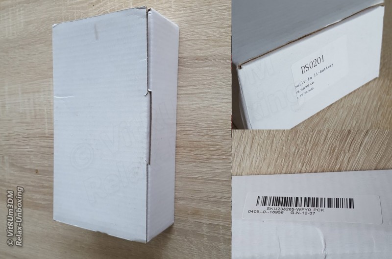
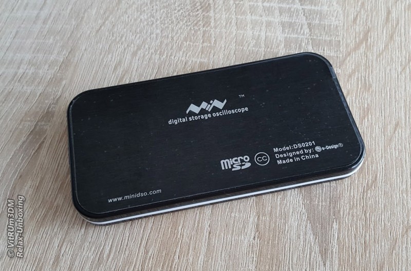
Как я понял данный осциллограф выпускается уже давно и до сих пор пользуется популярностью, хоть и не высокоточный и во многом уступает старшим братьям. Итак, получил, распаковал, коробка без полиграфии, несколько этикеток указывают на модель и SKU в магазине.
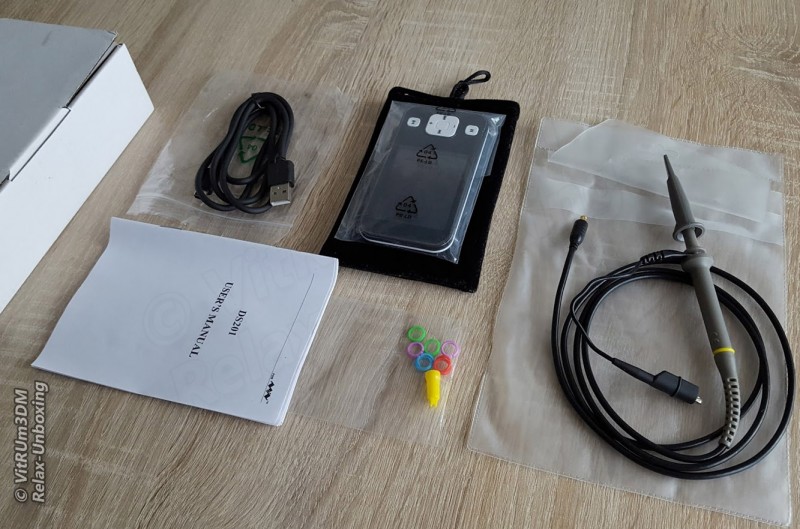
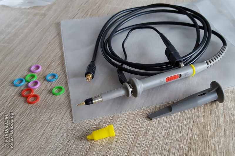
Комплектация: осциллограф, мягкий бархатистый чехол для хранения и переноски осциллографа, щуп с крокодилом, пластиковые колпачки, один с крючком, кабель с miniUSB разъемом, пластиковые кольца для щупа, и инструкция на английском.
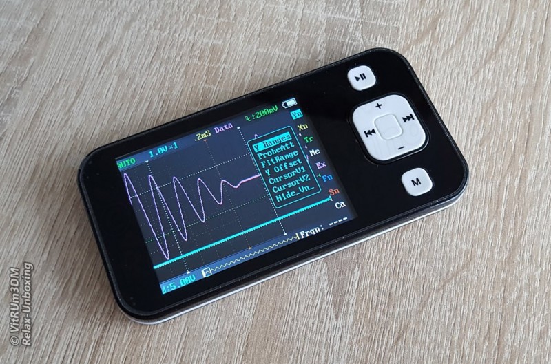
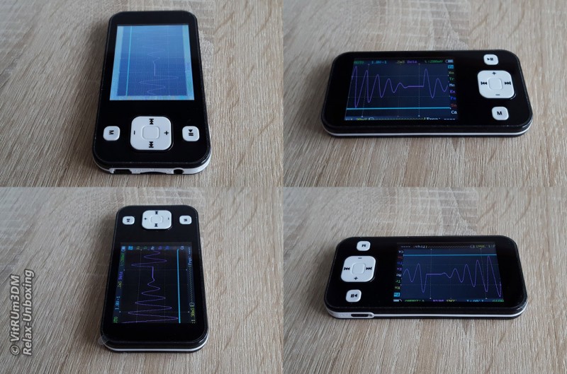
Осциллограф очень маленький и легкий, его легко можно спутать с MP3 плеером.
Флешка microSD необходима для сохранения данных в текстовом виде или картинках.
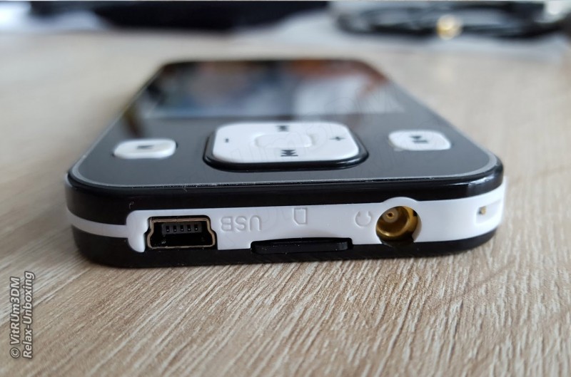
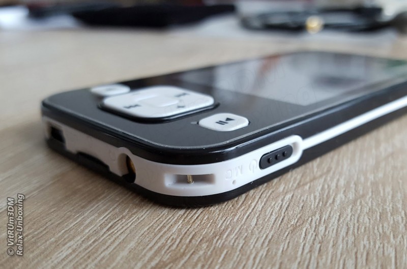
Отверстие с надписью MIC, конечно, нерабочее, а вот металлическая дужка это генератор импульсов.
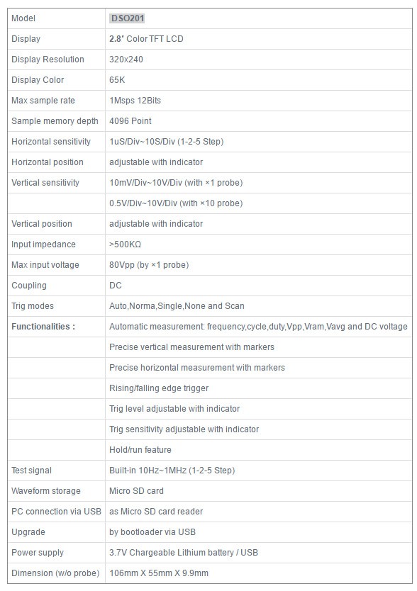
Технические характеристики, устройства очень скромные, как по мне это скорее обучающий набор, чем измерительный прибор, хотя и при помощи даже этого прибора можно проводить измерения, пусть и простые.
В инструкции сказано, что полоса пропускания 1 МГц. Об этом уже говорилось в предыдущем обзоре что это фикция, на самом деле более 100 кГц частоты сильно искажаются и от прошивки это не зависит. Технические характеристики очень скромные, при помощи этого прибора можно проводить простые измерения.
В устройстве стоит аккумулятор на 550mAh, этого хватит для работы устройства до 3-4 часов. Корпус не разборный, точнее он склеен двухсторонним скотчем, вскрыть пластиковый корпус без повреждений не получиться.
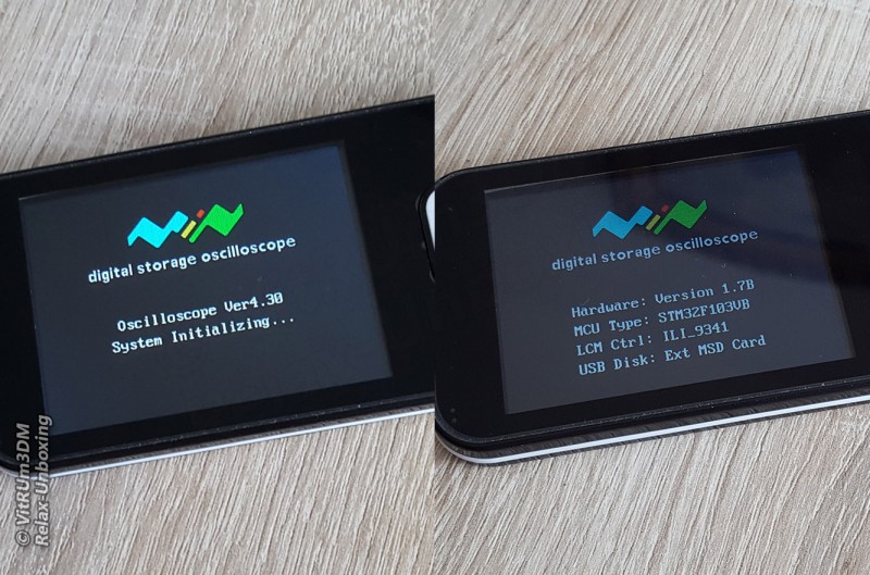
Дисплей TFT 320×240, всего один угол засвечивается.
Версия прошивки: Ver4.30.
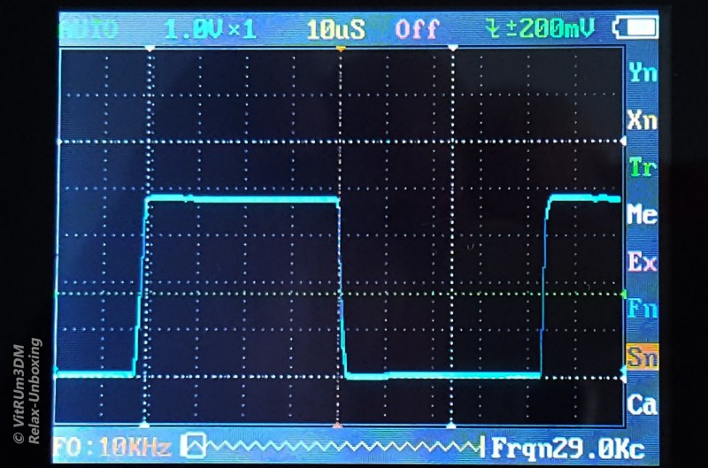
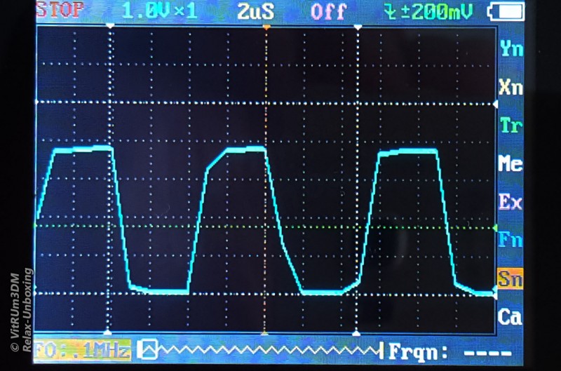
В осциллографе DSO201 встроен свой генератор прямоугольных импульсов.
10KHz
20KHz
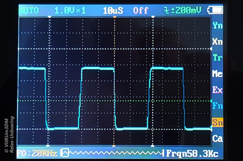
Выше 100KHz сигнал уже сильно искажен.
Для обзора спаял генератор прямоугольных импульсов на NE555, много места не занимает, пусть лежит, еще пригодится в будущем.
Картинка все та же, выше 100KHz сигнал искажен.
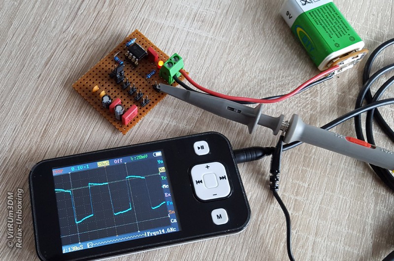
Схема генератора прямоугольных импульсов.
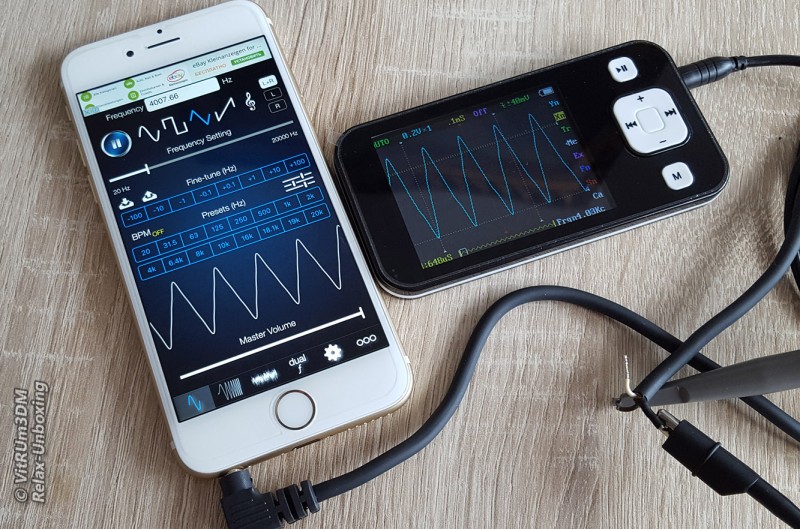
Для проверки других импульсов использовал смартфон и специальный софт.
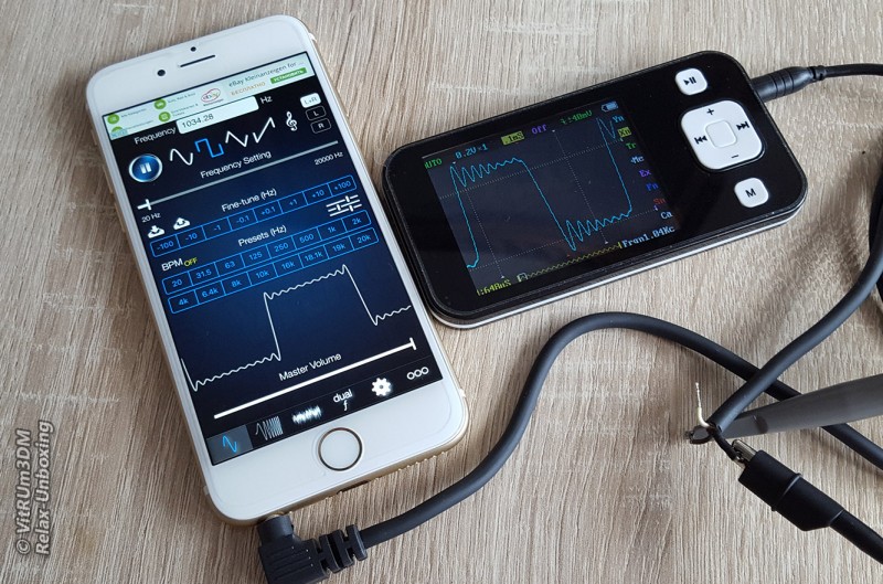
Меню полностью символьное, сначала думал буду долго разбираться, но уже через полчаса я разобрался в этой головоломке.
Кому интересно могут прочитать инструкцию на русском языке здесь.
При желании можно поменять прошивку, на дисплее будут отображаться больше данных, свежие прошивки можно найти по адресу .
Учтите, обновления затрагивают только интерфейс и практически никак не влияют на технически параметры. В осциллографе стоит контроллер ARM Cortex M3 (STM32F103VB).
С прибором я еще на ты поэтому на видео я разговариваю не уверенно ))
Для меня, начинающего электронщика, этот осциллограф не имеет недостатков, как по мне, тут шумы минимальны, TFT дисплей устарел но все параметры можно увидеть отчетливо, тормозов замечено не было, на все нажатия откликается быстро. Пожалуй чехол для хранения мог быть и побольше, не хватает места для щупа. И цена вполне приемлемая за такой функционал.
Товар для написания обзора предоставлен магазином. Обзор опубликован в соответствии с п.18 Правил сайта.
Главная
› Видео › DSO Nano v2 осциллограф цифровой, 2 канала х 1МГц
Опубликовано 28.03.2012
Ведущий Антон Панкратов
Тэги:
измерения, осциллограф, обработка сигналов
Цифровые осциллографы — это самые распространенные контрольно-измерительные приборы в мире. Обусловлено это тем, что с их помощью можно производить широкий спектр выполняемых работ. Прежде всего, это ремонт электронного оборудования, проектирование и обучение. DSO Nano v2 это 2-х канальный цифровой, запоминающий осциллограф с полосой пропускания до 1МГц …
Смотрите также
2:57
Мультиметр APPA-82RH
4:56
Некоторые особенности радиосвязи в космосе
2:17
GOS-620FG осциллограф и генератор
4:53
РЛС
2:23
Пирометры OPTEX S80 и U80
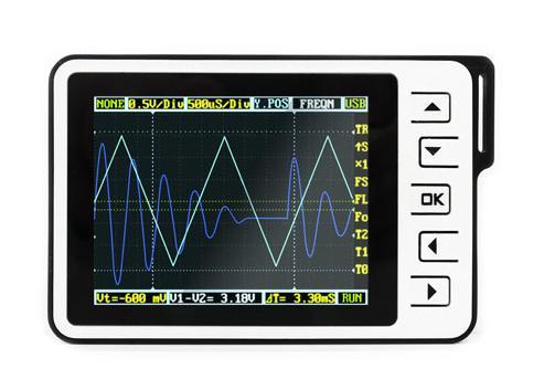
DSO Nano v2 is a Digital Storage Oscilloscope designed for basic electronic engineering tasks. The device runs on the ARM Cortex™-M3 32 bit platform, providing basic waveform monitoring with extensive functions. It features a 320 x 240 full-color TFT LCD, micro SD card storage slot, portable probes, LiPo Battery, USB connection and signal generator. Its palm size and handy features make it great for in-field diagnosis, quick measurement, and hobbyist projects. Schematics and source code files are also openly available for re-innovating.
This is an upgraded version of the previous Nano, with multiple improvements.
What’s new?
- Upgraded to steel alloy case for:
- Mechanical endurance
- Noise shielding
- Easier assembly
- Unibody PCB design for better reliability
- Complete charging circuit with LTC4054 IC
- Dedicated channel for signal generator.
- Extra button for quick-access features
- Fixed battery connector
- Compact size (95mm x 62mm x 13mm, 76g)
- Updated software (something beyond v2.4 is in the works)
Model: TOL131B2P
Features
- Portable and lightweight
- Color display
- Waveform storage and playback
- 6 triggering modes
- 200Khz Analog Bandwidth
- Complete measurement markers and signal characteristics
- Built-in Signal Generator
- Accessories available
- Open Source
Cautions
The ground probe of the DSO Nano is connected directly to the ground line of the USB port. This means that, when using the Nano with a PC, the PC’s ground will be tied to the measurement target’s ground. Do not connect the Nano to a circuit and computer simultaneously unless the computer and circuit share a common ground.
Specifications
Key Specs
| Display | Full Color 2.8″ TFT LCD 65K 320×240 |
| Analog bandwidth | 0 — 200KHz |
| Max sample rate | 1Msps 12Bits |
| Sample memory depth | 4096 Point |
| Horizontal sensitivity | 1uS/Div~10S/Div |
| Horizontal position | adjustable with indicator |
| Vertical sensitivity | 10mV/Div~10V/Div (with ×1 probe) |
| 0.5V/Div~100V/Div (with ×10 probe) | |
| Vertical position | adjustable with indicator |
| Input impedance | >500K6 |
| Max input voltage | 80Vpp (by ×1 probe) |
| Coupling | DCs |
| Trig modes | Auto, Normal, Single, None, Scan and Fit |
| Rising/Falling edge/level trigger | |
| Trig level adjustable with indicator | |
| Trig sensitivity adjustable with indicator | |
| Waveform Functions | Auto measurement: frequency, cycle time, duty cycle, peak voltage, RMS voltage, Average voltage and DC voltage |
| Precise vertical measurement with markers | |
| Precise horizontal measurement with markers | |
| Hold/Run | |
| Signal Generator | 10Hz~1MHz square wave |
| Waveform storage | Micro SD card |
| PC connection via USB | as SD card reader |
| Upgrade | USB |
| Power supply | 500mAh 3.7V Lithium battery / USB |
| Dimension (w/o probe) | 95mm*62mm*13mm |
| Weight | 76 gram |
Usage
Structure

Basic Operation
Left/Right buttons are mainly used to navigate through menu items. The selected menu item will be highlighted; its corresponding screen element will blink. Press UP/Down buttons to adjust. The OK button controls display/hide markers or confirm operations.
Pressing A (Run/Stop) Button once will freeze the current display. Press ‘A’ again to resume. The B (Shift) Button is used for quick functions.
Throughout this text, adjustable items will be labeled in red.

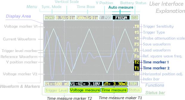
User Interface Overview
The screen is broken into a central display area and 3 operation bars around it. The menu on the top provides the most frequently-used adjustments to signal display. The status bar on the bottom provides precise measurement results and monitoring status. Adjust more advanced functions with the column of function icons on the right.
Zooming on Signals
Move the cursor to the Vertical Scale and Time Base to start exploring the signal display. Press the up/down buttons to adjust the voltage/div or time/div. Each “div” is a grid unit «division» of the screen; count the divisions to estimate a quick measurement. The vertical scale ranges from 10mV/div to 10V/div. The time base ranges from 1uS/div to 10S/div. Beware that in the larger time bases the display may look frozen, since 10S/div means it takes 120 seconds to refresh whole the screen (12 divs wide).
The waveform might be out of the range of the display even in the appropriate voltage/div setting. You can change the Y position to move the waveform up and down to center the wave onscreen. The Y position marker indicates 0V for your reference.
Press button A to freeze the current display (setting the status to HOLD) and press again to resume refreshing (status RUN). With the status on HOLD, you can select the T0 icon and press the up/down buttons to pan back and forth. Press the OK button to display or hide the X position marker (a yellow dotted vertical line).
Triggering Modes
The Nano has six triggering modes, accessible in the top left corner of the screen. These are:
AUTO: Always refresh the display, and synchronize when triggered.
NORM (al): Display synchronized waveform when triggered, and blank if not triggering.
SING (le): Display triggered waveform and hold, then blank again before triggering.
SCAN: Repeatedly sweep waveform onscreen left to right.
NONE: Refresh unsynchronized waveform ignoring triggering.
FIT: Automatically adjust vertical and horizontal scale to display waveform.
| Mode | Trigger | Display Waveform | Synchronization | Example Applications |
|---|---|---|---|---|
| AUTO | Yes | Always | Yes | General use |
| NORM | Yes | Triggered | Yes | Only watch periodic signals |
| SING | Yes | Triggered | Auto-hold | Capture a random pulse |
| SCAN | No | Always | No | Keep monitoring signals |
| NONE | No | Always | No | Watch an unsynchronized waveform |
| FIT | Yes | Auto-adjust | Yes | Easily watch periodic signals |
To set the triggering level, move cursor to Vt = ??.?mV and press the up/down buttons. Press OK to display or hide the trigger level markers (horizontal green dotted lines). To fine tune triggering, you may tweak the trigger sensitivity range TR and the trigger type. By default the trigger type is set to up S which means the trigger will fire when the signal crosses from the lower trigger line to the higher line. Down S will likewise trigger on a falling signal edge.
This could prevent mistaken triggering caused by noise, especially while measuring fast low-amplitude signals. If you set the sensitivity to 0, where the two trigger level markers overlap each other, you get level triggering. Please refer to Wikipedia for more informaiton on oscilloscope triggering.
Measurement
Auto measurement is useful for quickly exploring signal characteristics. Measurement options include frequency, cycle time, duty cycle, peak voltage, RMS voltage, average voltage and DC voltage. Please note that frequency, cycle time and duty cycle can only be measured while triggering.
To get a more precise measurement, use the measurement markers. T2 and T1 control the time markers, the two vertical dotted lines. A precise time difference between two marker positions is displayed in «time measure» near bottom of the screen. The V1 marker and V2 marker can be adjusted directly from the «voltage measure» result panel («V1-V2=? V») at the bottom center of the screen.
Pressing the OK button in a menu item will hide or show the corresponding line onscreen.
Waveform Storage
Please note : For the device with firmware app2.6, it is not necessary to the execute the third step .
Waveforms can be saved to an SD card or loaded to the display. You need a microSD card to do this (not included). Please note that SDHC cards (high-speed cards larger than 2 GB) are not supported for now. Follow the below steps to set up your microSD card:
- Make sure your SD card supports SPI mode. (Most SDHC cards over 2GB do not.
- Format your SD card with the FAT16 filesystem.
- Create a new file named FILEXXX.DAT in your SDcard root (file size must be bigger than 1KB). Or directly download SrcFileForSave and uncompress it into SD card root.
When the microSD card is prepared, the FS (file save) and FL (file load) icons are enabled. Press the OK button on FS to save a waveform, or on FL to load the waveform from the microSD card.
Signal Generator
The 3.5mm audio jack under the mini USB port is used for the signal generator. It outputs a square wave from 10Hz to 1MHz. Frequency can be adjusted via Fo («frequency out»). The peak voltage is the same as the supplied power, or approximately 3.7v if powered from battery, and 5v when powered by USB.
Power Supply
The DSO Nano can be powered by the internal 500mAh LiPo battery or by the external mini-USB port. Charging takes about 2 hours 20 minutes to reach 4.12V. A brand-new unit can only run about 1 hour by battery, but the battery life will be extended after the LiPo battery is fully charged.

Firmware and Upgrades
DSO Nano firmware update methods(App Ver2.4 and below)
1. Download «DfuSe USB Device Firmware Upgrade» and install . On Linux and Mac OS X you cuold use dfu-util(0.5 or newer).
2. Use USB cable connect DSO Nano with PC, press and hold down key, switch on power, untill DSO Nano displays «Please Connect to USB Host, DSO201 Device Firmware Upgarde Ver 2.0». If it is the first time connection, it will be prompted to install device drivers. You could find the corresponding driver in the «ST official development kit program» installation directory. In the default installation directory path»C:ProgramFileSTMicroelectronicsSoftwareDfuSeDriverx86″ When PC connection is detected, it will display «Firmware Upgrading…Please Wait».
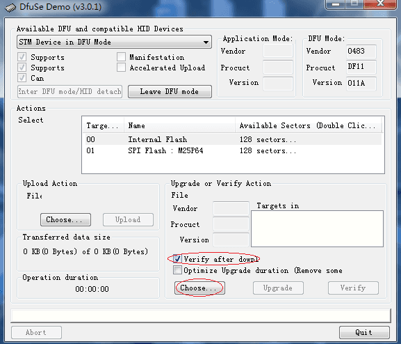
3. Run «Dfuse Demo» on PC, check «Verify after download», check «Choose» to select firmware, check «Upgarde»to upload firmware.(e,g «DS0201_APP_V2.40.dfu».»DS0201_LIB_V2.2.dfu»).Please note that both APP firmware and LIB firmware files needs to be programmed while upgarding.
4. Shut down and reactivate power to use new firmware.
DSO Nano firmware update methods(App Ver2.6):
1. Use USB cable connect DSO Nano with PC, press and hold down key, switch on power, DSO Nano will display «Device Firmware Upgrade V3.22A. Please copy Hex or Bin file to the DFU virtual USB disk». Wait till PC detects DFU virtual USB disk.
2. Download the DSO Nano firmware, copy both of hex files into DFU virtual USB disk(e.g»201AP263.hex».»LIB_A227.hex»). Wait till it change to «LIB_A227.err» and «201AP263.rdy».
3. Shut down and reactivate power to use new firmware.
Please note different device of Dfu corresponse different firmware , please download corresponsing firmware of your device in Resourses.
FAQ
- What is the maximum input voltage when using a 10x probe on the DSO Nano v2?
The maximum input voltage could be 80Vpp. So when using a 10x probe on the Nano DSO, it could be 800 Vpp. However, we did not test that, and we are not responsible for any damage and injury because of measuring high voltage.
- What is the difference between APP Ver2.6 and APP Ver2.4 ?
Firmware for APP Ver2.4 and APP Ver2.6 are different files in format. Firmware for APP Ver2.4 of LIB format suffixe is compatible with Nano which with DFU Ver2.0. Firmware for APP Ver2.6 of HEX format suffixe is compatible with Nano which with DFU Ver3.0. Besides, APP Ver2.6 is more humanized, you could directly save wavaform to SD Card as file in DAT format or PNG format.
Resources
- DSO Nano v2 Manual v0.91B
- DSO Nano Hardware v2.6 Layout.pdf
- DSO Nano Hardware v2.6 Shcematic.pdf
Firmware(.dfu files) for DSO Nano of DFU Ver2.0:
- DSO Nano Official Firmware App2.4
- BenF Firmware v3.64 Thank Benf for sharing this great firmware.
Firmware(.hex files) for DSO Nano of DFU Ver3.22
- DSO Nano Official Firmware App2.6
- BenF Firmware v3.64 Thank Benf for sharing this great firmware and Alf arranging it to work with DFU Ver3.22
External Links
- DSO Nano On SeeedStudio Forum
- Pocket Oscilloscope-DS0201 forum
- Firmware Update Released
Please note that firmwares on the above link is only support DSO Nano with DFU Ver3.0 , don’t use this firmware to upgrade DSO Nano with DFU Ver2.0 or lower.
How to buy
- Click here to buy : DSO Nano v2
See Also
- DSO Nano
- DSO Nano v1
- DSO Quad
Licensing
This documentation is licensed under the Creative Commons Attribution-ShareAlike License 3.0 Source code and libraries are licensed under GPL/LGPL, see source code files for details.
Copyright (c) 2008-2016 Seeed Development Limited (www.seeedstudio.com / www.seeed.cc)
This static html page was created from http://www.seeedstudio.com/wiki
Мини-осциллограф DSO Nano v2 — Страница 2 — ChipTuner Forum
![]()
| Прошивки Hyundai SIM2K от Strit | Прошивки Magneti Marelli VAG от Art-Pro | Прошивки Peugeot/Citroen от Art-Pro | Прошивки Kia SIM2K-241 от Strit |
Мини-осциллограф DSO Nano v2
-
Закрытая тема.
Страница 2 из 3
-

Features
- Portable and lightweight
- Color display
- Waveform storage and playback
- 6 triggering modes
- 200Khz Analog Bandwidth
- Complete measurement markers and signal characteristics
- Built-in Signal Generator
- Accessories available
- Open Source
Cautions
The ground probe of the DSO Nano is connected directly to the ground line of the USB port. This means that, when using the Nano with a PC, the PC’s ground will be tied to the measurement target’s ground. Do not connect the Nano to a circuit and computer simultaneously unless the computer and circuit share a common ground.
Specifications
Key Specs
Display Full Color 2.8″ TFT LCD 65K 320×240 Analog bandwidth 0 — 200KHz Max sample rate 1Msps 12Bits Sample memory depth 4096 Point Horizontal sensitivity 1uS/Div~10S/Div Horizontal position adjustable with indicator Vertical sensitivity 10mV/Div~10V/Div (with ×1 probe) 0.5V/Div~100V/Div (with ×10 probe) Vertical position adjustable with indicator Input impedance >500K6 Max input voltage 80Vpp (by ×1 probe) Coupling DCs Trig modes Auto, Normal, Single, None, Scan and Fit Rising/Falling edge/level trigger Trig level adjustable with indicator Trig sensitivity adjustable with indicator Waveform Functions Auto measurement: frequency, cycle time, duty cycle, peak voltage, RMS voltage, Average voltage and DC voltage Precise vertical measurement with markers Precise horizontal measurement with markers Hold/Run Signal Generator 10Hz~1MHz square wave Waveform storage Micro SD card PC connection via USB as SD card reader Upgrade USB Power supply 500mAh 3.7V Lithium battery / USB Dimension (w/o probe) 95mm*62mm*13mm Weight 76 gram Usage
Structure
Basic Operation
Left/Right buttons are mainly used to navigate through menu items. The selected menu item will be highlighted; its corresponding screen element will blink. Press UP/Down buttons to adjust. The OK button controls display/hide markers or confirm operations.
Pressing A (Run/Stop) Button once will freeze the current display. Press ‘A’ again to resume. The B (Shift) Button is used for quick functions.
Throughout this text, adjustable items will be labeled in red.
User Interface Overview
The screen is broken into a central display area and 3 operation bars around it. The menu on the top provides the most frequently-used adjustments to signal display. The status bar on the bottom provides precise measurement results and monitoring status. Adjust more advanced functions with the column of function icons on the right.
Zooming on Signals
Move the cursor to the Vertical Scale and Time Base to start exploring the signal display. Press the up/down buttons to adjust the voltage/div or time/div. Each “div” is a grid unit «division» of the screen; count the divisions to estimate a quick measurement. The vertical scale ranges from 10mV/div to 10V/div. The time base ranges from 1uS/div to 10S/div. Beware that in the larger time bases the display may look frozen, since 10S/div means it takes 120 seconds to refresh whole the screen (12 divs wide).
The waveform might be out of the range of the display even in the appropriate voltage/div setting. You can change the Y position to move the waveform up and down to center the wave onscreen. The Y position marker indicates 0V for your reference.
Press button A to freeze the current display (setting the status to HOLD) and press again to resume refreshing (status RUN). With the status on HOLD, you can select the T0 icon and press the up/down buttons to pan back and forth. Press the OK button to display or hide the X position marker (a yellow dotted vertical line).
Triggering Modes
The Nano has six triggering modes, accessible in the top left corner of the screen. These are:
AUTO: Always refresh the display, and synchronize when triggered.
NORM (al): Display synchronized waveform when triggered, and blank if not triggering.
SING (le): Display triggered waveform and hold, then blank again before triggering.
SCAN: Repeatedly sweep waveform onscreen left to right.
NONE: Refresh unsynchronized waveform ignoring triggering.
FIT: Automatically adjust vertical and horizontal scale to display waveform.Comparison table of the triggering modes
Mode Trigger Display Waveform Synchronization Example Applications AUTO Yes Always Yes General use NORM Yes Triggered Yes Only watch periodic signals SING Yes Triggered Auto-hold Capture a random pulse SCAN No Always No Keep monitoring signals NONE No Always No Watch an unsynchronized waveform FIT Yes Auto-adjust Yes Easily watch periodic signals To set the triggering level, move cursor to Vt = ??.?mV and press the up/down buttons. Press OK to display or hide the trigger level markers (horizontal green dotted lines). To fine tune triggering, you may tweak the trigger sensitivity range TR and the trigger type. By default the trigger type is set to up S which means the trigger will fire when the signal crosses from the lower trigger line to the higher line. Down S will likewise trigger on a falling signal edge.
This could prevent mistaken triggering caused by noise, especially while measuring fast low-amplitude signals. If you set the sensitivity to 0, where the two trigger level markers overlap each other, you get level triggering. Please refer to Wikipedia for more informaiton on oscilloscope triggering.
Measurement
Auto measurement is useful for quickly exploring signal characteristics. Measurement options include frequency, cycle time, duty cycle, peak voltage, RMS voltage, average voltage and DC voltage. Please note that frequency, cycle time and duty cycle can only be measured while triggering.
To get a more precise measurement, use the measurement markers. T2 and T1 control the time markers, the two vertical dotted lines. A precise time difference between two marker positions is displayed in «time measure» near bottom of the screen. The V1 marker and V2 marker can be adjusted directly from the «voltage measure» result panel («V1-V2=? V») at the bottom center of the screen.
Pressing the OK button in a menu item will hide or show the corresponding line onscreen.
Waveform Storage
Please note : For the device with firmware app2.6, it is not necessary to the execute the third step .
Waveforms can be saved to an SD card or loaded to the display. You need a microSD card to do this (not included). Please note that SDHC cards (high-speed cards larger than 2 GB) are not supported for now. Follow the below steps to set up your microSD card:
- Make sure your SD card supports SPI mode. (Most SDHC cards over 2GB do not.
- Format your SD card with the FAT16 filesystem.
- Create a new file named FILEXXX.DAT in your SDcard root (file size must be bigger than 1KB). Or directly download SrcFileForSave and uncompress it into SD card root.
When the microSD card is prepared, the FS (file save) and FL (file load) icons are enabled. Press the OK button on FS to save a waveform, or on FL to load the waveform from the microSD card.
Signal Generator
The 3.5mm audio jack under the mini USB port is used for the signal generator. It outputs a square wave from 10Hz to 1MHz. Frequency can be adjusted via Fo («frequency out»). The peak voltage is the same as the supplied power, or approximately 3.7v if powered from battery, and 5v when powered by USB.
Power Supply
The DSO Nano can be powered by the internal 500mAh LiPo battery or by the external mini-USB port. Charging takes about 2 hours 20 minutes to reach 4.12V. A brand-new unit can only run about 1 hour by battery, but the battery life will be extended after the LiPo battery is fully charged.
Firmware and Upgrades
DSO Nano firmware update methods(App Ver2.4 and below)
1. Download «DfuSe USB Device Firmware Upgrade» and install . On Linux and Mac OS X you cuold use dfu-util(0.5 or newer).
2. Use USB cable connect DSO Nano with PC, press and hold down key, switch on power, untill DSO Nano displays «Please Connect to USB Host, DSO201 Device Firmware Upgarde Ver 2.0». If it is the first time connection, it will be prompted to install device drivers. You could find the corresponding driver in the «ST official development kit program» installation directory. In the default installation directory path»C:ProgramFileSTMicroelectronicsSoftwareDfuSeDriverx86″ When PC connection is detected, it will display «Firmware Upgrading…Please Wait».
3. Run «Dfuse Demo» on PC, check «Verify after download», check «Choose» to select firmware, check «Upgarde»to upload firmware.(e,g «DS0201_APP_V2.40.dfu».»DS0201_LIB_V2.2.dfu»).Please note that both APP firmware and LIB firmware files needs to be programmed while upgarding.
4. Shut down and reactivate power to use new firmware.
DSO Nano firmware update methods(App Ver2.6):
1. Use USB cable connect DSO Nano with PC, press and hold down key, switch on power, DSO Nano will display «Device Firmware Upgrade V3.22A. Please copy Hex or Bin file to the DFU virtual USB disk». Wait till PC detects DFU virtual USB disk.
2. Download the DSO Nano firmware, copy both of hex files into DFU virtual USB disk(e.g»201AP263.hex».»LIB_A227.hex»). Wait till it change to «LIB_A227.err» and «201AP263.rdy».
3. Shut down and reactivate power to use new firmware.
Please note different device of Dfu corresponse different firmware , please download corresponsing firmware of your device in Resourses.
FAQ
- What is the maximum input voltage when using a 10x probe on the DSO Nano v2?
The maximum input voltage could be 80Vpp. So when using a 10x probe on the Nano DSO, it could be 800 Vpp. However, we did not test that, and we are not responsible for any damage and injury because of measuring high voltage.
- What is the difference between APP Ver2.6 and APP Ver2.4 ?
Firmware for APP Ver2.4 and APP Ver2.6 are different files in format. Firmware for APP Ver2.4 of LIB format suffixe is compatible with Nano which with DFU Ver2.0. Firmware for APP Ver2.6 of HEX format suffixe is compatible with Nano which with DFU Ver3.0. Besides, APP Ver2.6 is more humanized, you could directly save wavaform to SD Card as file in DAT format or PNG format.
Resources
- DSO Nano v2 Manual v0.91B
- DSO Nano Hardware v2.6 Layout.pdf
- DSO Nano Hardware v2.6 Shcematic.pdf
Firmware(.dfu files) for DSO Nano of DFU Ver2.0:
- DSO Nano Official Firmware App2.4
- BenF Firmware v3.64 Thank Benf for sharing this great firmware.
Firmware(.hex files) for DSO Nano of DFU Ver3.22
- DSO Nano Official Firmware App2.6
- BenF Firmware v3.64 Thank Benf for sharing this great firmware and Alf arranging it to work with DFU Ver3.22
External Links
- DSO Nano On SeeedStudio Forum
- Pocket Oscilloscope-DS0201 forum
- Firmware Update Released
Please note that firmwares on the above link is only support DSO Nano with DFU Ver3.0 , don’t use this firmware to upgrade DSO Nano with DFU Ver2.0 or lower.
How to buy
- Click here to buy : DSO Nano v2
See Also
- DSO Nano
- DSO Nano v1
- DSO Quad
Licensing
This documentation is licensed under the Creative Commons Attribution-ShareAlike License 3.0 Source code and libraries are licensed under GPL/LGPL, see source code files for details.
Copyright (c) 2008-2016 Seeed Development Limited (www.seeedstudio.com / www.seeed.cc)
This static html page was created from http://www.seeedstudio.com/wiki
Мини-осциллограф DSO Nano v2 — Страница 2 — ChipTuner Forum

Прошивки Hyundai SIM2K от Strit Прошивки Magneti Marelli VAG от Art-Pro Прошивки Peugeot/Citroen от Art-Pro Прошивки Kia SIM2K-241 от Strit Мини-осциллограф DSO Nano v2
-
Закрытая тема.
Страница 2 из 3
-
offline
Диагностика, ремонт, ГБО, дизели, бензин
- Регистрация:
- 17.02.2006
- Сообщений:
- 12,762
- Адрес:
- г. Пятигорск, лички нет
Мотодок все цилиндры сразу показывает, поэтому можно сравнивать между собой их, да ещё по нескольким измерениям…
А DSO nano — один канал, памяти только экран. Можно в память на карту сохранить и потом смотреть… ну в самом деле, относительную компрессию на нём не померить.
Только исправность конкретной катушки, конкретного провода, конкретного датчика, но ДПКВ уже несколько неудобно смотреть, маловат экран, а импульсов от прорези до прорези очень много, весь цикл окинуть взглядом затруднительно.Последний раз редактировалось Олег_Б; 04.01.2011 в 10:24. -

offline
Преподаватель
- Регистрация:
- 24.01.2006
- Сообщений:
- 625
- Адрес:
- г. Новочеркасск
Олег_Б, осциллограмму на форсунке или на клапане адсорбера можешь выложить?
-
Тогда Вам, имхо, типа
должно подойти.
-
offline
Диагностика, ремонт, ГБО, дизели, бензин
- Регистрация:
- 17.02.2006
- Сообщений:
- 12,762
- Адрес:
- г. Пятигорск, лички нет
-
offline
Преподаватель
- Регистрация:
- 24.01.2006
- Сообщений:
- 625
- Адрес:
- г. Новочеркасск
И так, и так. Частоту укажет?
И еще, можно ли сохранненый файл разглядеть на компьютере? -

Сейчас диагностика
- Регистрация:
- 05.03.2006
- Сообщений:
- 16,005
- Адрес:
- г.Курчатов
-
offline
Преподаватель
- Регистрация:
- 24.01.2006
- Сообщений:
- 625
- Адрес:
- г. Новочеркасск
-

offline
Ремонт АКПП
- Регистрация:
- 03.02.2010
- Сообщений:
- 478
- Адрес:
- Дагестан.Избербаш
а прибор на русском языке или только английский
-
offline
Диагностика, ремонт, ГБО, дизели, бензин
- Регистрация:
- 17.02.2006
- Сообщений:
- 12,762
- Адрес:
- г. Пятигорск, лички нет
Название кнопок на английском. Надписи 0.2v/Div и 1mS/Div выглядят вполне понятными. Пользуюсь им на столе периодически, подмотку настраиваю например. Как экспресс-осцилограф использую Асю-экспресс. Просто у меня все осцилы относительно габаритные, не очень удобно под капотом лазить, или в салоне. И длительность впрыска осцилографом смотреть — бесполезное занятие.
А вот именно синал увидеть, что есть 12 вольт, есть разумная длительность и амплитуда, или сигнал на все форсунки приходит, и есть выбросы от индукции в конце, то есть через обмотки идёт ток, а цилиндр не работает — это именно то. Пользоваться ДСО-нано неудобнее, чем обычным осцилографом, поскольку у обычного все регулировки доступны сразу, а на ДСО-нано надо сначала курсор подвести к нужному параметру, а потом уже двумя другими кнопками двигать параметр в нужную сторону.Добавлено через 1 час 20 минутОсциллограмма форсунки выглядит так же, как катушка зажигания, только после закрытия форсунки нет горения искры.
Последний раз редактировалось Олег_Б; 05.03.2011 в 12:30.Причина: Добавлено сообщение
-

offline
диагност
- Регистрация:
- 21.06.2007
- Сообщений:
- 2,603
- Адрес:
- Саратов
Там есть очень важный «горбик», по которому можно оценить состояние механики форсунки.
-
offline
Электрик
- Регистрация:
- 10.03.2006
- Сообщений:
- 263
- Адрес:
- Казань
Появились в этой же серии и 4 канальные осцилографики. Вообще все выглядит красиво и заманчиво. Что скажет Олег_Б?
-
offline
Ремонт АКПП
- Регистрация:
- 03.02.2010
- Сообщений:
- 478
- Адрес:
- Дагестан.Избербаш
-
offline
Диагностика, ремонт, ГБО, дизели, бензин
- Регистрация:
- 17.02.2006
- Сообщений:
- 12,762
- Адрес:
- г. Пятигорск, лички нет
Скажу как тестер осциллограф пойдёт, но для начинающих неплохо Ася-экспресс, там многие действия автоматизированы. ДСО-нано на специалиста всё же, надо передвигать курсор на нужную настройку и потом двигать эту настройку куда надо… Это не модель, с которой надо начинать ознакомление с осцилом.
4 канала? Это такой? ССЫЛКА -
offline
Электрик
- Регистрация:
- 10.03.2006
- Сообщений:
- 263
- Адрес:
- Казань
-
offline
Диагностика, ремонт, ГБО, дизели, бензин
- Регистрация:
- 17.02.2006
- Сообщений:
- 12,762
- Адрес:
- г. Пятигорск, лички нет
Там 2 аналоговых и 2 цифровых канала, то есть это не совсем 4 канала будет. Как осциллограф — 2 канала, как логический анализатор — 4 канала. Я так понимаю.
-

offline
эмбдедер
- Регистрация:
- 13.11.2009
- Сообщений:
- 2,711
- Адрес:
- Чебоксары
Сегодня получил этот девайс с диалэкстрима ($73 с компенсированным щупом) — никаких нареканий нет. Да и вообще, за несколько десятков моих опытов работы с диалэкстримом — только приятные впечатления, по крайней мере в пай-пал ни разу пожаловаться не пришлось.Добавлено через 24 минуты
Да, у моего девайса на ак-ре были перепутаны «плюс» и «минус». Про такую особенность знал, т.к. прочёл на диалэстриме, поэтом перед включением отщёлкнул провода и поставил как надо.
Последний раз редактировалось Antel; 24.05.2011 в 16:29.Причина: Добавлено сообщение
-
offline
Диагностика, ремонт, ГБО, дизели, бензин
- Регистрация:
- 17.02.2006
- Сообщений:
- 12,762
- Адрес:
- г. Пятигорск, лички нет
Ну не смотрю я «наной» управление адсорбером, поскольку мне этот сигнал вообще не нужен. Ни наной, ни мотодоком, ни асей-экспресс…
Ася-экспресс месяц назад сломалась, надо отправить в ремонт. Некогда, надеюсь через Ростов куда-то съездить в ближайшее время и по пути в ремонт завести её. Поэтому под капотом DSO-3064 использую, а вот потребовалось проверить наличие сигнала тахометра в панели, от контролера вроде «уходит», а панель откручена уже была.
Выставляю на DSO nano ожидаемую частоту и амплитуду, массу там же в разъёме цепляю и сигнальным — по другим контактам прохожу, поскольку ни цвета, ни номера контакта тахометра не знаю. Опа! Есть сигнал. Перегазовка… он! Значит сам стрелочный прибор приказал долго жить.То есть проще выставлять развёртку и усиление, какие должны быть, и искать.
Версия моего 2.4
Пытаюсь разобраться, как записать новую версию, с компом так и не соеденился. Кто знает, может подскажет пошагово?Последний раз редактировалось Олег_Б; 06.11.2011 в 01:45. -

offline
Основной инструмент паяльник
- Регистрация:
- 15.12.2008
- Сообщений:
- 720
- Адрес:
- Оренбург
DSO Nano V1.1 ищет коннекта с компом при включении питания с нажатой клавишей DOWN.
-
offline
Диагностика, ремонт, ГБО, дизели, бензин
- Регистрация:
- 17.02.2006
- Сообщений:
- 12,762
- Адрес:
- г. Пятигорск, лички нет
А комп его не видит. Ставил программы, как на сайте seeed написано, никак не видит комп этот девайс.
-
offline
радиодело
- Регистрация:
- 28.12.2010
- Сообщений:
- 6
- Адрес:
- Kazakhstan Актау
Всем доброе утро. Приобрел DSO QUAD на деалекстриме. С прежними моделями сравнить не могу, так как не юзал их. Из достоинств, открытый и закрытый вход. можно наблюдать генерацию кварца 27 мгц. Реально же 1-2 мгц без особых искажений, встроенный генератор прямоуг. импульсов до 8 Мгц. Неудобная навигация в меню, маленькими трехпозиционными кнопочками. Привыкать долго. Обошлось все в 170 баксов, в комплекте только 2 щупа, один из них для цифры. (или генератора) Удобная автокалибровка диапазонов по верт. отклонению. Но есть небольшая погрешность у меня по крайней мере. при подаче на закрытый вход 5в, на дисплее 4,88в. как после авто так и после ручной калибровки. Теперь вопрос начинающего автоэлектрика. Подскажите пожалуйста какие датчики можно использовать для наблюдения высоковольтных импульсов зажигания. Можно ли изготовить самодельные и как, спрашиваю потому что у нас с приобретением оборудования в городе напряг. И если что можно изготовить самому, то стараемся сделать.
-
offline
Инженер
- Регистрация:
- 13.11.2011
- Сообщений:
- 3
- Адрес:
- Воркута, республика Коми
Аналогично, так же интересует этот вопрос, осцилла не имею, но но хотел бы приобрести подобный для начала, в первую очередь привлекает мобильность и наличие нескольких каналов, но хочется увеличить функциональную возможность данного или подобного прибора в диагностике, прошу знающих людей подсказать. Спасибо.
Последний раз редактировалось Евгений 11; 04.01.2012 в 23:01. -
offline
Диагностика, ремонт, ГБО, дизели, бензин
- Регистрация:
- 17.02.2006
- Сообщений:
- 12,762
- Адрес:
- г. Пятигорск, лички нет
Как дополнение или как резерв — хорошо, как основной осциллограф — утомительно, лучше с той же Автоас-экспресс начать, экран больше, настройки разнесены. А здесь в четырёх кнопках то, что на осциллографе в 20 не помещается… Если первый осциллограф, ИМХО не самый удачный выбор…
Впрочем не настаиваю…
Надо учесть максимальное входное напряжение и использовать щупы и датчики, которые не превышают это напряжение (70 вольт, кажется?).
То есть обязательно делитель на 10, если смотреть в машине, поскольку там до 400 вольт — легко, это напряжение самоиндукции всяких реле, катушек и форсунок…Последний раз редактировалось Олег_Б; 17.03.2012 в 15:52. -
offline
Инженер
- Регистрация:
- 13.11.2011
- Сообщений:
- 3
- Адрес:
- Воркута, республика Коми
Спасибо за пояснение, к Автоас-экспрес присматривался, но сейчас ещё появился Диско- Экспресс от Мотор Мастер, по цене более лояльный, но отзывом по нему пока ещё не нашёл, это я так понял аналог Автоас-Экспресс или несколько иначе?
-
offline
Диагностика, ремонт, ГБО, дизели, бензин
- Регистрация:
- 17.02.2006
- Сообщений:
- 12,762
- Адрес:
- г. Пятигорск, лички нет
Не держал в руках «Диско».
Обычный осциллограф: Подключаемся и смотрим, какой там сигнал
DSO Nano: Ставим в настройках «сигнал» и смотрим, есть он или нет.
То есть развёртку и усиление надо знать, поскольку настройки устанавливаются дольше. Лично я его (DSO Nano) использую только при поиске сигнала скорости на панели, когда она откручена, держать ноутбук с Автоас-экспресс или просто осциллограф неудобно — предметы габаритные, в том числе Овоны, Хантеки и Риголы всякие… А наладонник — то что нужно.
Последний раз редактировалось Олег_Б; 05.01.2012 в 23:10. -

offline
СТО
- Регистрация:
- 02.03.2006
- Сообщений:
- 164
- Адрес:
- Хакассия
Привет всем!
Вот программы и новая прошивка для DSO NANO v2.
Стало на много удобней пользоваться да косяки поправили .
Сам ставил всё ОК. -

offline
Радиоинженер. Эксплуатация, ремонт, монтаж передающего ТВ/РВ оборудования и АФУ.
- Регистрация:
- 31.07.2009
- Сообщений:
- 68
- Адрес:
- Кубань
Приобрёл подобный «прибор», двухканальный правда. Попользовался чутка, даже тахометр на одной автине запустил с его помощью. В «минусе» — неудобно настройки «крутить» после классических аналоговых осциллоскопов, доступ долгий очень через кнопочки. В «плюсе» — габариты (в карман сунул и пошёл) и автономное питание, очень удобно «на выезде» или на улице, вне гаража. Ну и два канала тоже неплохо. Как «показометр» — вполне сносная цацка. Теперь буду продавать «рабочую лошадку» С1-67, может нужен кому?
-
offline
ремонт авто
- Регистрация:
- 23.02.2009
- Сообщений:
- 109
- Адрес:
- Курская обл.
Coldun, не совсем понял, что не работало? Недавно приобрёл, на стадии ознакомлениня выявил проблемку, на канале А, при установке входного диапазона меньше 1В/дел (0,5 ;0,2, и.т.д.).сигнал пропадает иногда, похоже, пока холодный, как погреется чуть, тогда нормально. И напряжение при этом показывает чуть меньше, на 0,01-0,02 В.
И что делать? Это оно.?
Вход канала А:Миниатюры:
Последний раз редактировалось DEFO; 16.03.2012 в 01:38.
Страница 2 из 3
-
Закрытая тема.
Здесь присутствуют: 1 (пользователей: 0 , гостей: 1)Текущее время: 22:55. Часовой пояс GMT +4.-
-
December 18 2012, 10:11
Categories: - Недвижимость
- Отзывы
- Cancel
если коротко — я весьма доволен. фактически для процентов 70 типичных проверок можно использовать вместо стационарного/USB осцила. а то и больше.
как уже писАл — не хватает переключателя режима входа открытый/закрытый, что не позволит смотреть допустим незначительные пульсации на АКБ. но тут ИМХО аппаратная доработка понадобится. хотелось бы иметь инверсию сигнала — не очень удобно смотреть вторичку. тут решается программно. лично мне еще бы «эмулятор вольтметра» — большие цифры текущего значения, мин/макс помельче и стрелочку/барграф.
а так — однозначно необходимая каждому диагносту вещь. без вариантов вообще. маст хэв. либо двухканальный. тогда можно будет синхронизироваться по второму каналу и закрыть 90% функций USB осцила.
посмотрел лямбда-зонд и подключил датчик разряжения. пассат Б3 с моновпрыском — не самая удачная машина для проверки ДР. ну и фотки получились не сильно резкие и слегка пересвеченные — уж извиняйте. но представление о работе прибора дают исчерпывающее, ИМХО.
датчик разряжения:

можно поставить на паузу и погонять вправо-влево для просмотра большего количества периодов. удобно, хотя без привязки к цилиндру — не очень информативно. но позволит выявить явные аномалии. я правда забыл проверить в другом режиме — у него есть отображение со сглаживанием и без. возможно будет лучше/хуже. ну плюс жиклер можно попробовать менять/краник покрутить… ну как всегда с ДР — адаптация к конкретному мотору, вы ж понимаете.датчик кислорода (лямбда-зонд):

если не ошибаюсь — 0.1 или 0.2с/дел, буфера хватает на один экран, так что «погонять» на паузе не получится. отрисовывает в режиме реального времени, между старым и новым измерением ползет «черный провал» — его видно на фотке. очень понравилось. можно клиентов пугать. стандартный массовый провод коротковат, правда.общие впечатления после перепрошивки и более плотного чем в первый раз использования — трудносдерживаемый восторг

Это тоже интересно:
- Dso 138 инструкция на русском
- Dsg 5737 индезит посудомоечная машина инструкция
- Dt9208a мультиметр инструкция по применению на русском языке
- Dt9208a инструкция на русском измерение
- Dt838 цифровой мультиметр инструкция по применению на русском