- Manuals
- Brands
- Dahua Manuals
- Network Hardware
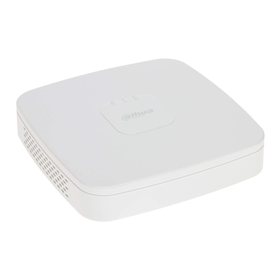
- Lite NVR2104-4KS2
- User manual
-
Contents
-
Table of Contents
-
Bookmarks
Quick Links
Questo manuale d’istruzione è fornito da trovaprezzi.it. Scopri tutte le offerte per
Dahua Lite
NVR2104-4KS2
o cerca il tuo prodotto tra le
migliori offerte di Videosorveglianza
Network Video Recorder User’s Manual
V 4.3.0
Related Manuals for Dahua Lite NVR2104-4KS2
Summary of Contents for Dahua Lite NVR2104-4KS2
-
Page 1
Questo manuale d’istruzione è fornito da trovaprezzi.it. Scopri tutte le offerte per Dahua Lite NVR2104-4KS2 o cerca il tuo prodotto tra le migliori offerte di Videosorveglianza Network Video Recorder User’s Manual V 4.3.0… -
Page 2: Table Of Contents
Table of Contents Features and Specifications …………………….. 13 Overview …………………………13 Features …………………………13 Specifications ……………………….14 Beneficio Smart 1U (S2) Series ………………… 14 1.3.1 1.3.2 Compact 1U(S2)Series ………………….17 1.3.3 Compact 1U Wireless Series ………………….19 Beneficio smart 1U / Beneficio smart 1U with 1 PoE port / Beneficio smart 1U with 8 PoE 1.3.4 ports / Beneficio smart 1U with wireless Series ………………
-
Page 3
Beneficio 1U Series …………………….. 72 2.1.5 2.1.6 Compact 1U(S2)/ 4K compact 1U (S2)/ Compact 1U 4K(S2) Series ……74 2.1.7 1U/1.5U/2U Series ……………………… 74 Beneficio 1.5U Series ……………………75 2.1.8 Beneficio 2U Series …………………….. 77 2.1.9 2.1.10 Beneficio Vertical 1U Series ………………….79 Rear Panel …………………………. -
Page 4
HDD Installation ……………………….. 120 Smart 1U Series ……………………..120 3.4.1 Mini 1U/Compact 1U Series ………………….121 3.4.2 3.4.3 1U Series ……………………….121 1.5U Series ……………………….122 3.4.4 General 2U Series …………………….. 122 3.4.5 3.4.6 Beneficio Vertical 1U Series ………………….123 CD-ROM Installation …………………….. -
Page 5
Preview Control Interface ………………….189 4.3.3 Right Click Menu ……………………..191 4.3.4 4.3.5 Edit View (Sequence) ……………………193 Preview Display Effect Setup ………………….. 195 4.3.6 Fisheye (Optional) …………………….. 202 4.3.7 PTZ …………………………..204 PTZ Settings………………………. 204 4.4.1 PTZ Control ……………………….. 206 4.4.2 Record File ……………………….. -
Page 6
4.10.1 Account ……………………….308 System Info……………………….317 4.10.2 Voice …………………………320 4.10.3 4.10.4 RS232 ………………………… 322 Broadcast ……………………….324 4.10.5 Security ……………………….326 4.10.6 4.10.7 Auto Maintain ……………………..328 Backup ……………………….. 328 4.10.8 Default ………………………… 332 4.10.9 4.10.10 Upgrade ……………………….333 4.11 Logout /Shutdown/Restart …………………… -
Page 7
5.13.1 IVS (Behavior Analytics) …………………… 445 Plate recognition ……………………..446 5.13.2 Human Face ………………………. 447 5.13.3 5.14 Alarm …………………………. 448 5.15 Log out …………………………449 5.16 Un-install Web Control …………………….. 450 Glossary …………………………..451 FAQ …………………………… 452 Appendix A HDD Capacity Calculation …………………. 457 Appendix B Compatible Network Camera List……………… -
Page 8
Welcome Thank you for purchasing our network video recorder! This user’s manual is designed to be a reference tool for your system. Please open the accessory bag to check. Contact your local retailer ASAP if something is missing or damaged in the bag. -
Page 9: Beneficio 1U / Beneficio Entry-Level 1U/ Beneficio 1U With 1 Poe Port/ Beneficio 1U With
Cybersecurity Recommendations Cybersecurity Recommendations Mandatory actions to be taken towards cybersecurity 1. Change Passwords and Use Strong Passwords: The number one reason systems get “hacked” is due to having weak or default passwords. It is recommended to change default passwords immediately and choose a strong password whenever possible.
-
Page 10
● You do not need to forward any ports for individual cameras if they are all connected to a recorder on site; just the NVR is needed. 7. Disable Auto-Login on SmartPSS: Those using SmartPSS to view their system and on a computer that is used by multiple people should disable auto-login. -
Page 11
cannot be accessed directly. 16. Isolate NVR and IP Camera Network The network your NVR and IP camera resides on should not be the same network as your public computer network. This will prevent any visitors or unwanted guests from getting access to the same network the security system needs in order to function properly. -
Page 12
Important Safeguards and Warnings 1.Electrical safety All installation and operation here should conform to your local electrical safety codes. An apparatus with CLASS I construction shall be connected to a MAINS socket outlet with a protective earthing connection. … -
Page 13
CAUTION RISK OF EXPLOSION IF BATTERY IS REPLACED BY AN INCORRECT TYPE. DISPOSE OF USED BATTERIES ACCORDING TO THE INSTRUCTIONS. Standards Approvals For our Wi-Fi series product, please refer to the following important notices. This device complies with Part 15 of the FCC Rules. Operation is subject to the following two conditions: (1) This device may not cause harmful interference, and (2) This device must accept any interference received, including interference that may cause undesired… -
Page 14: Features And Specifications
1 Features and Specifications 1.1 Overview This series NVR is a high performance network video recorder. This series product support local preview, multiple-window display, recorded file local storage, remote control and mouse shortcut menu operation, and remote management and control function. This series product supports center storage, front-end storage and client-end storage.
-
Page 15: Specifications
Through network, sending audio/video data compressed by IPC or NVS to client-ends, then the data will be decompressed and display. Support max 128 connections at the same time. Network Transmit audio/video data by HTTP, TCP, UDP, MULTICAST, Monitor RTP/RTCP and etc.
-
Page 16
Model General Series Ports 8 PoE Ports Series Series Interface H.264 Decode Video Decode Type Max 4-ch 1080P 30fps or 8-ch 720P 30fps or 16-ch D1 30fps Decode Capability Video Video Input 4/8/16-ch network 4/8-ch network compression video input compression video input 1-channel VGA analog video output… -
Page 17
Model General Series Ports 8 PoE Ports Series Series Port and RS232 Port Indicator RS485 Port 2 peripheral USB2.0 ports. USB Port Network 1 RJ45 10/100Mbps self-adaptive Ethernet port. Connection Power Port power socket. power socket. power socket. Power adapter Power adapter Power… -
Page 18: Compact 1U(S2)Series
Model General Series Ports 8 PoE Ports Series Series Dimension 205mm×206.75mm× 205mm×206.75mm× 425mm×95mm×260 45.2mm 45.2mm Weight 0.5kg~2kg (No HDD) Installation Desk installation Mode 1.3.2 Compact 1U(S2)Series Model General Series 4 PoE Ports Series 8 PoE Ports Series 4/8/16-ch series 4/8-ch series product support 4/8 HD System System product…
-
Page 19
Model General Series 4 PoE Ports Series 8 PoE Ports Series Alarm Alarm Input Alarm Output Function Storage 1 built-in SATA port Multiple-Chann Max 4-channel 1080P or 8-channel 720P or 16-channel D1 playback el Playback Port and RS232 Port Indicator RS485 Port 2 peripheral USB2.0 ports. -
Page 20: Compact 1U Wireless Series
1.3.3 Compact 1U Wireless Series Model Compact 1U Wireless Series 4/8-ch series product support 4/8 HD connection respectively. Total System System bandwidth supports 80Mbps. Resources Embedded Linux real-time operation system Operation WEB/Local GUI Interface Decode Video Decode H.264/MJPEG/MPEG4 Type Max 8-ch 1080P or 4-ch 3M or 2-ch 5M. Decode Capability Video…
-
Page 21: Beneficio Smart 1U / Beneficio Smart 1U With 1 Poe Port / Beneficio Smart 1U With 8 Poe Ports / Beneficio Smart 1U With Wireless Series
Model Compact 1U Wireless Series Power Button Power On-off Button Receiver Window Clock Built-in clock. One power status indicator light. Indicator Light One network status indicator light. One HDD status indicator light. General Power <30W (No HDD) Consumption Working ﹣10℃~﹢55℃ Temperature Working 10℅~90℅…
-
Page 22
Model Beneficio Beneficio Beneficio Beneficio smart smart 1U with smart 1U with smart 1U with Series port 8 PoE ports wireless Series Series Series 1-channel VGA analog video output Video Output 1-ch HDMI output. Version number is 1.4 HDMI Window Split 1/4/8/9/16-window 1/4-window 1-ch bidirectional talk input… -
Page 23: Beneficio Mini 1U / Beneficio Mini 1U With 1 Poe Port / Beneficio Mini 1U With 8 Poe Ports Series
Model Beneficio Beneficio Beneficio Beneficio smart smart 1U with smart 1U with smart 1U with Series port 8 PoE ports wireless Series Series Series Clock Built-in clock. One power status indicator light. Indicator Light One network status indicator light. One HDD status indicator light. Power <10W (No HDD) General…
-
Page 24
Model Beneficio mini 1U Beneficio mini 1U Beneficio mini 1U Series with 1 PoE port with 8 PoE ports Series Series 1/4/8/9/16-window Window Split 1-ch bidirectional talk input Audio Audio Input 1-ch bidirectional talk output Audio Output Audio G.711a Compression Standard Alarm Alarm Input… -
Page 25: Beneficio 1U(S2) Series
Model Beneficio mini 1U Beneficio mini 1U Beneficio mini 1U Series with 1 PoE port with 8 PoE ports Series Series Working ﹣10℃~﹢55℃ Temperature Working 10℅~90℅ Humidity Air pressure 86kPa~106kPa Dimension 325mm×250.58mm×51mm Weight 0.5kg~1kg (No HDD) Desk installation Installation Mode 1.3.6 Beneficio 1U(S2) Series Model General Series…
-
Page 26
Model General Series 4 PoE Ports Series 8 PoE Ports Series Audio G.711a Compression Standard Alarm Alarm Input Alarm Output Function Storage 2 built-in SATA ports Multiple-Channel Max 4-channel 1080P or 8-channel 720P or 16-channel D1 playback Playback Port and RS232 Port Indicator RS485 Port… -
Page 27: Beneficio Entry-Level 1U Series
Model General Series 4 PoE Ports Series 8 PoE Ports Series Weight 1.5kg~2.5kg (No HDD) Installation Mode Desk installation 1.3.7 Beneficio Entry-level 1U Series Model Beneficio Entry-level 1U Series System 4/8/16/32-channel series product support 4/8/16/32-channel HD System Resources connection respectively. Main stream bandwidth…
-
Page 28: Beneficio 1U / Beneficio 1U With 1 Poe Port / Beneficio 1U With 8 Poe Ports Series
One power port, power adapter. Input DC 12V. Power Port Power Button One button. At the rear panel. Power On-off One button. At the front-panel. Button Support IR remote control Receiver Window Clock Built-in clock. One power status indicator light. Indicator Light One network status indicator light.
-
Page 29
1/4/8/9/16-window Window Split 1-ch bidirectional talk input Audio Input Audio Audio Output 1-ch bidirectional talk output G.711a Audio Compression Alarm Input 4-ch alarm input Alarm Alarm Output 2-ch alarm output Function Storage 2 built-in SATA ports. Multiple-chan Max 8-channel 720P/4-channel 1080P playback at the same time. nel Playback Port and RS232 Port… -
Page 30: Beneficio 1U With 16 Poe Ports Series
Desk installation Installation 1.3.9 Beneficio 1U with 16 PoE Ports Series Model Beneficio 1U with 16 PoE Ports Series 16/32-channel series product support 4/8/16/32-channel System System Resources connection respectively. Main stream/sub stream bandwidth supports 200Mbps. Embedded Linux real-time operation system Operation System Operation…
-
Page 31: Professional 4K 1U / Professional 4K 1U With 8 Poe Ports / Professional 4K 1U With 16 Poe Ports Series
One button. At the rear panel. Power Button Power On-off Button Receiver Window Clock Built-in clock. Indicator Light One power status indicator light. One network status indicator light. One HDD status indicator light. <30W(No HDD) General Power Consumption Working -10℃~+55℃ Temperature 10℅-90℅…
-
Page 32
1-ch bidirectional talk input Audio Input Audio Audio Output 1-ch bidirectional talk output Audio G.711a, G.711u, PCM, G.726 (The bidirectional talk function supports Compression G.711a, G.711u, PCM only.) Alarm Input 4-ch alarm input Alarm 2-ch relay output Alarm Output Function Storage 2 built-in SATA ports. -
Page 33: Beneficio 1.5U / Beneficio 1.5U With 8 Poe Ports / Beneficio 1.5U With 16 Poe Ports Series
10℅-90℅ Working Humidity Air pressure 86kpa-106kpa Dimension General series: 375mm(W) × 56mm(H) × 281.4mm(D) PoE series: 375mm(W) × 53mm(H) × 327.3mm(D) Weight General series: : 1.60Kg (No HDD) 8 PoE series: 2.60Kg 16 PoE series: 2.70Kg Desk/rack installation Installation 1.3.11 Beneficio 1.5U / Beneficio 1.5U with 8 PoE ports / Beneficio 1.5U with 16 PoE ports Series Model Beneficio…
-
Page 34: Professional 4K 1.5U / Professional 4K 1.5U With 16 Poe Ports Series
One RS232 port to debug transparent COM data. Port and RS232 Port Indicator RS485 port One RS485 port to control PTZ. Support various protocols. 2 peripheral USB2.0 ports. One at the front panel and one at the rear USB2.0 Port panel.
-
Page 35
Audio G.711a, G.711u, PCM, G726 (The bidirectional talk supports Compression G.711a, G.711u, PCM only.) Standard Video Input 16/32/64-ch network compression video input 2-channel VGA Video Output Video 2-channel HDMI. Parameters Video Compression H.264 Standard Window Split 1/4/8/9/16/25/36/64-screen. Mode Alarm Input 16-channel Alarm Parameters… -
Page 36: Beneficio 2U / Beneficio 2U With 16Poe Ports Series
4 indicator lights. 1 system running status indicator light Indicator Light 1 HDD indicator light 1 network status indicator light 1 power status indicator light Power AC90~264V Power General series: 16.7W(No HDD) Consumption 16 PoE series: 17.5W(No HDD) Working -10℃~55℃…
-
Page 37: Beneficio Vertical 1U Series
output) ) Including one controllable DC +12V output. Function Storage 4 built-in SATA ports. 1 external eSATA port. Multiple-channel Max 8-channel 720P/4-channel 1080P playback at the same time. Playback Port and RS232 Port One RS232 port to debug transparent COM data. Indicator One RS485 port to control PTZ.
-
Page 38
WEB/Local GUI Operation Interface Video Compression H.264/MJPEG/MPEG4 Decode Decode Capacity Max supports 16-channel D1, or 8-channel 720P, or 4-channel 1080P, or 4*3M or 2*5M decode. 8/16/32-ch network compression video input Video Input Video Video Output 1-channel VGA analog video output. 1-ch HDMI output. -
Page 39: Professional 4K 2U / Professional 4K 2U With 16 Poe Ports Series
Working Temperature -10℃~+55℃ 10℅-90℅ Working Humidity Air pressure 86kpa-106kpa Dimension 100mm×220mm×146mm Weight 1.5kg~2.5kg(No HDD) Desk installation Installation 1.3.15 Professional 4K 2U / Professional 4K 2U with 16 PoE ports Series Professional 4K 2U / Professional 4K 2U with 16 PoE Specifications ports series Industrial embedded micro processor…
-
Page 40: Smart 1U (S2) Series
Backup Mode Flash disk, eSATA, DVD burner. IPv4/IPv6/HTTP/UPnP/NTP/SADP/SNMP/PPPoE/DNS/FTP/ Network Network Protocol Function ONVIF(Version 2.4)/PSIA SATA Port 8 SATA Ports eSATA Port 1 eSATA port RS232 Port 1 RS232 port. To debug and transmit COM data. 1 RS485 port. To control peripheral PTZ and etc. Support RS485 Port various protocols.
-
Page 41
General 4K 4K Smart 1U 4K Smart 1U Model Smart (S2) with 4 PoE (S2) with 8 PoE (S2) Series ports Series ports Series 4/8/16-channel 4/8-channel series 8/16-channel series System Resources series product product main stream product main stream main stream support support… -
Page 42: Compact 1U (S2) Series
General 4K 4K Smart 1U 4K Smart 1U Model Smart (S2) with 4 PoE (S2) with 8 PoE (S2) Series ports Series ports Series Privacy Mask Each channel supports 4 privacy mask zones Record Storage Overwrite Backup Mode USB device/DVD burner Port and Network Protocol IPv4/IPv6/HTTP/UPnP/NTP/SADP/SNMP/PPPoE/DNS/FTP/ON…
-
Page 43
General 4K Compact 1U 4K Compact 1U Model Compact (S2) with 4 PoE (S2) with 8 PoE (S2) Series ports Series ports Series Industrial embedded micro processor System Main Processor Embedded Linux operation system 4/8/16-channel 4/8-channel series 8/16-channel series System series product product main stream… -
Page 44
General 4K Compact 1U 4K Compact 1U Model Compact (S2) with 4 PoE (S2) with 8 PoE (S2) Series ports Series ports Series Multiple-Channel Max 8-channel 1080P playback Playback Each video supports PAL 396(22*18)/ NTSC 330(22×15) detection Motion Detect zones, support multiple sensivityly levels. Each channel supports 4 privacy mask zones Privacy Mask Record Storage… -
Page 45: 1U (S2) Series
General 4K Compact 1U 4K Compact 1U Model Compact (S2) with 4 PoE (S2) with 8 PoE (S2) Series ports Series ports Series Dimensions(mm) 224.9*47.6*260(D*H*W) Weight 1.2Kg (No HDD) 1.6Kg (No HDD) 2.1Kg (No HDD) Installation Mode Desk/rack installation 1.3.18 4K 1U (S2) Series General Model (S2)
-
Page 46
General Model (S2) (S2) with (S2) with with 16 PoE (S2) ports Series Series ports ports Series Series Video H.264 Compress Standard Window 1/4/8/9/16/3 1/4-window 1/4/8/9-wind 1/4/8/9/16/3 2-window 2-window Split Alarm Alarm 4-channel input Input Alarm 2-channel output:1-channel relay output, 1-channel 12V control Output Decode Decode… -
Page 47
General Model (S2) (S2) with (S2) with with 16 PoE (S2) ports Series Series ports ports Series Series Port RS232 Port RS485 Port 2 peripheral USB ports: one USB 2.0 port at the front panel and one USB Port USB3.0 port at the rear panel Network 1 RJ45 10/100/1000Mbps self-adaptive Ethernet port. -
Page 48: 1U (S2) With 24 Poe Ports Series
General Model (S2) (S2) with (S2) with with 16 PoE (S2) ports Series Series ports ports Series Series Dimensions( 320mm × 48.2mm × 375mm(D*H*W) Weight 3.2Kg (No HDD) 4.1Kg (No HDD) Installati Desk/rack installation on Mode 1.3.19 4K 1U (S2) with 24 PoE Ports Series Model 4K 1U (S2) with 24 PoE Ports series Main…
-
Page 49
recording>motion detection recording>schedule recording. Multiple-chan Max 16-channel 1080P playback at the same time. nel Playback Motion Detect Each screen supports 396/330((PAL 22×18, NTSC 22×15) detection zones. Various sensitivity levels. Privacy Mask Each channel supports 4 privacy mask zones. Record Mode Overwrite Flash disk, DVD burner. -
Page 50: 1.5U (S2) Series
420mm×482.6 mm×44 mm Dimension Weight 4.5Kg (No HDD) Installation Desk/rack installation 1.3.20 4K 1.5U (S2) Series Model General 4K 1.5U (S2) 4K 1.5U (S2) with 16 PoE ports series Industrial embedded micro processor System Main Processor Embedded Linux operation system 16/32-channel series product 16/32-channel series…
-
Page 51
Model General 4K 1.5U (S2) 4K 1.5U (S2) with 16 PoE ports series The record priority: Manual record>Alarm record>Motion detect record>Schedule record Multiple-Channel Max 8-channel 1080P playback Playback Motion Detect Each video supports PAL 396(22*18)/ NTSC 330(22×15) detection zones, support multiple sensivityly levels. Privacy Mask Each channel supports 4 privacy mask zones Record Storage… -
Page 52: 1.5U (S2) With 24 Poe Ports
Model General 4K 1.5U (S2) 4K 1.5U (S2) with 16 PoE ports series Air pressure 86kPa~106kPa Dimensions(mm) 405*72*440(D*H*W) Weight 7.00Kg (No HDD) Installation Mode Desk/rack installation 1.3.21 4K 1.5U (S2) with 24 PoE ports Model 4K 1.5U (S2) with 24 PoE ports Series Main Processor Industrial embedded micro processor System…
-
Page 53
Motion Detect Each screen supports 396/330((PAL 22×18, NTSC 22×15) detection zones. Various sensitivity levels. Privacy Mask Each channel supports 4 privacy mask zones. Record Mode Overwrite Backup Mode Flash disk, DVD burner. Port and Network Protocol IPv4/IPv6/HTTP/UPnP/NTP/SADP/SNMP/PPPoE/DNS/FTP/ONVI F(Version 2.4)/PSIA Indicator SATA Port eSATA Port RS232 Port… -
Page 54: 2U (S2) Series
4.7Kg Weight (No HDD) Installation Desk/rack installation 1.3.22 4K 2U (S2) Series Model General 4K 2U (S2) Series 4K 2U (S2) with 16 PoE Ports Series Industrial embedded micro processor System Main Processor Embedded Linux operation system 16/32-channel series product 16/32-channel series product…
-
Page 55
Model General 4K 2U (S2) Series 4K 2U (S2) with 16 PoE Ports Series Multiple-Channel Max 8-channel 1080P playback Playback Each video supports PAL 396(22*18)/ NTSC 330(22×15) detection Motion Detect zones, support multiple sensivityly levels. Each channel supports 4 privacy mask zones Privacy Mask Record Storage Overwrite… -
Page 56: Beneficio 4K Smart 1U(S2) Series
Model General 4K 2U (S2) Series 4K 2U (S2) with 16 PoE Ports Series 445.5mm×90.65mm×439.7mm(D*H*W) Dimensions(mm) Weight 9.80Kg (No HDD) Desk/rack installation Installation Mode 1.3.23 Beneficio 4K Smart 1U(S2) Series Model General Beneficio Beneficio 4K Smart Beneficio 4K Smart 4K Smart 1U(S2) 1U(S2) with 4 PoE 1U(S2) with 8 PoE Series…
-
Page 57
Model General Beneficio Beneficio 4K Smart Beneficio 4K Smart 4K Smart 1U(S2) 1U(S2) with 4 PoE 1U(S2) with 8 PoE Series Ports Series Ports Series Standard Window Split 1/4/8/9/16-window 1/4-window 1/4/8/9-window 1-ch bidirectional talk input Audio Audio Input 1-ch bidirectional talk output Audio Output Audio PCM,G.711a,G711u… -
Page 58
Model General Beneficio Beneficio 4K Smart Beneficio 4K Smart 4K Smart 1U(S2) 1U(S2) with 4 PoE 1U(S2) with 8 PoE Series Ports Series Ports Series eSATA Port RS232 Port RS485 Port 2 peripheral USB2.0 ports. USB Port HDMI Port Network 1 RJ45 10/100Mbps self-adaptive Ethernet 1 RJ45 Connection… -
Page 59: Compact 1U 4K(S2)Series
Model General Beneficio Beneficio 4K Smart Beneficio 4K Smart 4K Smart 1U(S2) 1U(S2) with 4 PoE 1U(S2) with 8 PoE Series Ports Series Ports Series Working 10℅~90℅ Humidity Air pressure 86kPa~106kPa 425mm × 260mm × Dimension 205mm×205mm×52mm 95mm Weight 0.9kg~1.0kg (No HDD) Installation Mode Desk installation 1.3.24 Compact 1U 4K(S2)Series…
-
Page 60
Model General Compact Compact Compact ( S2 ) with 4 PoE ( S2 ) with 8 PoE 1U 4K(S2) Series Ports Series Ports Series Video Output 1-channel VGA analog video output 1-channel HDMI video output, HDMI version is 1.4. VGA and HDMI output the video from the same video source. Video Compression Standard… -
Page 61
Model General Compact Compact Compact ( S2 ) with 4 PoE ( S2 ) with 8 PoE 1U 4K(S2) Series Ports Series Ports Series Port Network IPv4, IPv6, HTTP, NTP, DNS, ONVIF Indicator Protocol SATA Port eSATA Port RS232 Port RS485 Port 2 peripheral USB2.0 ports. -
Page 62: Beneficio 4K 1U(S2) Series
Model General Compact Compact Compact ( S2 ) with 4 PoE ( S2 ) with 8 PoE 1U 4K(S2) Series Ports Series Ports Series <10W (No HDD, no PoE connection) Power Consumption Working ﹣10℃~﹢50℃ Temperature Working 10℅~90℅ Humidity Air pressure 86kPa~106kPa Dimension 260mm×224mm×47.6mm…
-
Page 63
Model General Beneficio Beneficio Beneficio 4K 1U(S2) Series 1U(S2) with 4 PoE 1U(S2) with 8 PoE Ports Series Ports Series Video Video Input 4/8/16-ch network 4-ch network 8-ch network compression video compression video compression video input input input Video Output 1-channel VGA analog video output 1-channel HDMI video output, HDMI version is 1.4. -
Page 64
Model General Beneficio Beneficio Beneficio 4K 1U(S2) Series 1U(S2) with 4 PoE 1U(S2) with 8 PoE Ports Series Ports Series NVR local/network and etc. Record File Storage Peripheral USB device Backup Mode Port and Network IPv4, IPv6, HTTP, NTP, DNS, ONVIF Indicator Protocol SATA Port… -
Page 65: 1U (S2E) With 16 Poe Ports Series
Model General Beneficio Beneficio Beneficio 4K 1U(S2) Series 1U(S2) with 4 PoE 1U(S2) with 8 PoE Ports Series Ports Series One HDD status indicator light. Power DC12V 4A DC48V 1.5A DC53V 2.2A General Supplying <10W (No HDD, no PoE connection) Power Consumption ﹣10℃~﹢50℃…
-
Page 66
1/4/8/9/16/25/36-screen. Window Split Mode Alarm Alarm Input 4-channel Parameters 2-channel relay output Alarm Output MPEG4, MJPEG, H.264, H.265 Decode Decode Type Parameters Decode H.264/H.265: 64-channel×D1, 32-channel×720P, 16-channel 1080P; Capability 4-channel 4K. Functions Record Mode Manual recording, motion detection recording, schedule recording and alarm recording. -
Page 67: 1.5U (S2E) With 16 Poe Ports
Working -10℃~55℃ Temperature Working 10%~90%(No condensation) Humidity Dimensions 375mm×327.3mm×53mm (Including cushion) (W×H×D) Weight(No 2.7Kg (No HDD) HDD) Rack/desktop Installation Mode 1.3.27 4K 1.5U (S2E) with 16 PoE ports Specifications 4K 1.5U (S2E) with 16 PoE Ports Series System Main Industrial embedded micro processor Processor Operation Embedded LINUX system…
-
Page 68: 2U (S2E) With 16 Poe Ports
Each screen supports 396/330((PAL 22×18, NTSC 22×15) detection Motion Detect zones. Various sensitivity levels. Privacy Mask Each channel supports 4 privacy mask zones. Record Mode Overwrite Backup Mode Flash disk, eSATA, DVD burner. Network Network IPv4/IPv6/HTTP/UPnP/NTP/SADP/SNMP/PPPoE/DNS/FTP/ONVIF Function Protocol (Version 2.4) SATA Port 4 SATA Ports eSATA Port…
-
Page 69
Industrial embedded micro processor System Main Processor Operation Embedded LINUX system System System 16/32/64-channel main stream connection: supports Resources 160/320/320Mbps User Interface WEB, local GUI Audio Audio Input 1-ch MIC bidirectional talk audio input Parameters Audio Output 2-ch MIC bidirectional talk audio output G.711a, G.711u, PCM, G.726 (The bidirectional talk supports G.711a, Audio Compression… -
Page 70
2 USB 2.0 ports at the front panel and 2 USB3.0 ports at the rear USB Port panel. HDMI Port 2 HDMI ports Network Port 1 RJ45 10/100/1000Mbps self-adaptive Ethernet ports PoE Port 16 PoE ports: Port 1 to port 8 support ePoE function (300 meters@100Mbps,800 meters@10Mbps). -
Page 71: Front Panel And Rear Panel
2 Front Panel and Rear Panel 2.1 Front Panel 2.1.1 Beneficio smart 1U/Beneficio smart 1U(S2)/ 4K smart 1U (S2)/ Beneficio 4K Smart 1U(S2) Series The front panel is shown as in Figure 2-1. Figure 2-1 Please refer to the following sheet for detailed information. Name Function HDD status indictor light…
-
Page 72: Compact 1U Wireless Series
Icon Name Function Network status The red light becomes on when the indicator light network connection is abnormal. Power indicator The red light becomes on when the power light connection is OK. status The red light becomes on when HDD is indictor light abnormal.
-
Page 73: Beneficio Smart 1U With 8 Poe Port Series
2.1.4 Beneficio Smart 1U with 8 PoE port Series The front panel is shown as below. See Figure 2-4. Figure 2-4 Please refer to the following sheet for detailed information. Name Function Network status indicator The red light becomes on when the network light connection is abnormal.
-
Page 74
When playback, click these buttons to control playback bar. In text mode, input number 2(English character A/B/C) /3(English character D/E/F) Go to previous menu, or cancel current operation. When playback, click it to restore real-time monitor mode. Confirm current operation Enter ENTER Go to default button… -
Page 75: Compact 1U(S2)/ 4K Compact 1U (S2)/ Compact 1U 4K(S2) Series
Network Network error occurs or there is no network connection, the abnormal light becomes red to alert you. indicator light HDD error occurs or HDD capacity is below specified abnormal threshold value, the light becomes red to alert you. indicator light System is recording or not.
-
Page 76: Beneficio 1.5U Series
The 1.5U series front panel is shown as in Figure 2-8. Figure 2-8 The 2U series front panel is shown as in Figure 2-9. Figure 2-9 Please refer to the following sheet for front panel button information. Icon Name Function STATUS Status indicator light The blue light is on when the device is malfunction.
-
Page 77
Power button, press this button for three seconds to boot up Power button or shut down NVR. In textbox, click this button to switch between numeral, Shift Shift English(Small/Capitalized),donation and etc. Activate current control, modify setup, and then move up and down. -
Page 78: Beneficio 2U Series
In normal playback or pause mode, click this button to Reverse/Pau reverse || se/6 playback In reverse playback, click this button to pause playback. In text mode, input number 6 (English character M/N/O) In playback mode, playback the next video In menu setup, go to down ward of the dropdown list.
-
Page 79
Enable or disable tour. Activate current control, modify setup, and then move up and down. 、 Increase/decrease numeral. Down Assistant function such as PTZ menu. Shift current activated control, and then move left and right. Left/ Right When playback, click these buttons to control playback bar. Go to previous menu, or cancel current operation. -
Page 80: Beneficio Vertical 1U Series
In normal playback click this button to pause playback Play/Pause In pause mode, click this button to resume playback. Window switch Mult Click it to switch one-window/multiple-window. In real-time monitor mode it works as left/right direction key. Shuttle(outer Playback mode, counter clockwise to forward and clock wise to ring) backward.
-
Page 81
Figure 2-12 Please refer to the following sheet for front panel button information. Name Icon Function Power button Power button, press this button for three seconds to boot up or shut down NVR. One-window monitor mode, click this button to display assistant function: PTZ control and image color. -
Page 82: Rear Panel
HDD abnormal HDD error occurs or HDD capacity is below specified threshold indicator light value, the light becomes red to alert you. Network Network error occurs or there is no network connection, the light abnormal becomes red to alert you. indicator light Alarm indicator The light becomes on when an alarm occurred.
-
Page 83
Figure 2-16 Please refer to the following sheet for detailed information. Port Name Connection Function USB2.0 port. Connect to mouse, USB storage USB2.0 port device, USB burner and etc. 10M/100Mbps self-adaptive Ethernet port. Network port Connect to the network cable. High definition audio and video signal output port. -
Page 84: Beneficio Smart 1U (S2)/ Beneficio 4K Smart 1U(S2) Series
Port Name Connection Function MIC IN Audio input port Bidirectional talk input port. It is to receive the analog audio signal output from the devices such as microphone, pickup. Audio output port. It is to output the analog audio MIC OUT Audio output signal to the devices such as the sound box.
-
Page 85: Series
Figure 2-19 Please refer to the following sheet for detailed information. Port Name Connection Function Power socket For general series,input DC 12V/2A. Power input port For 4 PoE ports series,input DC 48V/1.25A. For 8 PoE ports series,input DC 48V/2A. …
-
Page 86
Figure 2-21 The beneficio mini 1U with 8 PoE ports series NVR rear panel is shown as in Figure 2-22. Figure 2-22 Please refer to the following sheet for detailed information. Port Name Connection Function USB2.0 port. Connect to mouse, USB storage USB2.0 port device, USB burner and etc. -
Page 87: Compact 1U(S2)/ Compact 1U 4K(S2)Series
Port Name Connection Function Audio output port. It is to output the analog audio MIC OUT Audio output signal to the devices such as the sound box. port Bidirectional talk output. Audio output on 1-window video monitor. Audio output on 1-window video playback.
-
Page 88: Compact 1U Wireless Series
Port Name Connection Function High definition audio and video signal output port. It High Definition transmits uncompressed high definition video and HDMI Media Interface multiple-channel data to the HDMI port of the display device. HDMI version is 1.4. VGA video output VGA video output port.
-
Page 89: Beneficio 1U (S2)/ Beneficio 4K 1U(S2) Series
Please refer to the following sheet for detailed information. Icon Name Function Power input Power socket. Input DC12V/2A. socket. 10M/100Mbps self-adaptive Ethernet port. Connect to Network port the network cable. USB2.0 port. Connect to mouse, USB storage device, USB2.0 port and etc.
-
Page 90: Poe Ports/ Beneficio 1U With 16 Poe Ports Series
Please refer to the following sheet for detailed information. Port Name Connection Function Power socket. For general series, input DC 12V/4A. Power input port For 4 PoE ports series, input DC 48V/1.5A. For 8 PoE ports series, input DC 53V 120W. 10M/100Mbps self-adaptive Ethernet port.
-
Page 91
The beneficio 1U with 1 PoE port series NVR rear panel is shown as below. See Figure 2-32. Figure 2-32 The beneficio 1U with 8 PoE ports series NVR rear panel is shown as below. See Figure 2-33. Figure 2-33 with 16 PoE Ports The beneficio 1U series rear panel is shown as below. -
Page 92
Name Function Audio output port. It is to output the analog audio signal MIC OUT Audio output port to the devices such as the sound box. Bidirectional talk output. Audio output on 1-window video monitor. Audio output on 1-window video playback. … -
Page 93: Professional 4K 1U/ Professional 4K 1U With 8 Poe Ports/ Professional 4K 1U With 16 Poe Ports/4K 1U (S2) With 24 Poe Ports/4K 1U (S2E) With 16 Poe Ports
2.2.8 Professional 4K 1U/ Professional 4K 1U with 8 PoE ports/ Professional 4K 1U with 16 PoE ports/4K 1U (S2) with 24 PoE Ports/4K 1U (S2E) with 16 PoE ports Series The professional 4K 1U series rear panel is shown as below. See Figure 2-35. Figure 2-35 The professional 4K 1U with 8 PoE ports rear panel is shown as below.
-
Page 94
Icon Port Name Function 10M/100M/1000Mbps self-adaptive Ethernet port. Network port Connect to the network cable. High definition audio and video signal output port. It High Definition transmits uncompressed high definition video and HDMI Media Interface multiple-channel data to the HDMI port of the display device. -
Page 95: Beneficio 1.5U / Beneficio 1.5U With 8 Poe Ports/ Beneficio 1.5U With 16 Poe Ports Series
Icon Port Name Function Power input port Input DC 12V/4A. Power on/off button. Power switch Bult-in Switch. Support PoE or ePoE function. For ePoE series product, port 1 to port 8 are the ePoE ports. ePoE port supports meters@100Mbps, 800 meters@10Mbps. Port 9 to PORTS port 16 are general PoE ports.
-
Page 96
Name Function MIC IN Audio input port Bidirectional talk input port. It is to receive the analog audio signal output from the devices such as microphone, pickup. Audio output port. It is to output the analog audio MIC OUT Audio output port signal to the devices such as the sound box. -
Page 97: Professional 4K 1.5U/ Professional 4K 1.5U With 16 Poe Ports/ Professional 4K 2U
Name Function Network port 10M/100M/1000Mbps self-adaptive Ethernet port. Connect to the network cable. eSATA eSATA port External SATA port. It can connect to the device of the SATA port. Please jump the HDD when there is peripheral connected HDD. USB2.0 port USB2.0 port.
-
Page 98
Figure 2-44 The 4K 1U (S2) with 24 PoE ports series rear panel is shown as below. See Figure 2-45. Figure 2-45 The 4K 1.5U (S2E) with 16 PoE ports series rear panel is shown as below. See Figure 2-46. Figure 2-46 The 4K 2U (S2E) with 16 PoE ports series rear panel is shown as below. -
Page 99
Name Function High definition audio and video signal output port. It High Definition transmits uncompressed high definition video and HDMI Media Interface multiple-channel data to the HDMI port of the display device. HDMI version is 1.4b. MIC IN Audio input port Bidirectional talk input port. -
Page 100: Smart 1U (S2) Series
Name Function +12V power output port. It can provide the power to +12V some peripheral devices such as the camera or the alarm device. Please note the supplying power shall be below 1A. RS-232 RS232 debug It is for general COM debug to configure IP address COM.
-
Page 101: Beneficio Vertical 1U Series
Please refer to the following sheet for detailed information. Port Name Connection Function USB port. Connect to mouse, USB storage device, USB port USB burner and etc. 10M/100Mbps self-adaptive Ethernet port. Network port Connect to the network cable. High definition audio and video signal output port. High Definition It transmits uncompressed high definition video…
-
Page 102
Figure 2-51 Please refer to the following sheet for detailed information. Name Function Power Power on/off button. switch Power input port Input DC 53V—2.3A MIC IN Audio input port Bidirectional talk input port. It is to receive the analog audio signal output from the devices such as microphone, pickup. -
Page 103: Compact 1U (S2) Series
Name Function Normal open alarm output port. Normal open 10M/100M/1000Mbps self-adaptive Ethernet port. Network port Connect to the network cable. USB3.0 port. Connect to mouse, USB storage device, USB3.0 port USB burner and etc. High definition audio and video signal output port. It High Definition transmits uncompressed high definition video and…
-
Page 104: 1U (S2) Series
Figure 2-54 Please refer to the following sheet for detailed information. Port Name Connection Function USB port. Connect to mouse, USB storage device, USB USB port burner and etc. Power socket. For general 4K compact 1U (S2): DC 12V/2A power. …
-
Page 105
Figure 2-56 The 4K 1U (S2) with eight PoE ports series rear panel is shown as below. See Figure 2-57. Figure 2-57 The 4K 1U (S2) with sixteen PoE ports series rear panel is shown as below. See Figure 2-58. Figure 2-58 Please refer to the following sheet for detailed information. -
Page 106: 1.5U (S2) Series
Name Function There are two types; NO (normal open)/NC 1~4 Alarm input port (normal close). 1~4 When your alarm input device is using external power, please make sure the device and the NVR have the same ground. Alarm input ground port. …
-
Page 107
The 4K 1.5U (S2) with sixteen PoE ports series rear panel is shown as below. See Figure 2-60. Figure 2-60 Please refer to the following sheet for detailed information. Name Function Power switch Power on-off button Power input AC90V~264V-12V12.5A/-53V2.83A port MIC IN Audio input port Bidirectional talk input port. -
Page 108: Beneficio 2U/Beneficio 2U With 16 Poe Ports Series
Name Function RS485_A port. It is the cable A. You can connect to RS-485 the control devices such as speed dome PTZ. communication RS485_B.It is the cable B. You can connect to the port control devices such as speed dome PTZ. CTRL 12V Controller 12V power output.
-
Page 109
The beneficio 2U with 16 PoE ports series NVR rear panel is shown as below. See Figure 2-62. Figure 2-62 Please refer to the following sheet for detailed information. Name Function Power switch Power on-off button Power input Input AC 100~240V. port MIC IN Audio input port… -
Page 110: 2U (S2) Series
Name Function RS485_A port. It is the cable A. You can connect to RS-485 the control devices such as speed dome PTZ. communication port RS485_B.It is the cable B. You can connect to the control devices such as speed dome PTZ. Controller 12V power output.
-
Page 111
The 4K 2U (S2) with sixteen PoE ports series rear panel is shown as below. See Figure 2-64. Figure 2-64 Please refer to the following sheet for detailed information. Name Function Power switch Power on-off button Power input AC90V~264V-12V12.5A/-53V2.83A port MIC IN Audio input port Bidirectional talk input port. -
Page 112: Alarm Connection
Name Function RS485_A port. It is the cable A. You can connect to RS-485 the control devices such as speed dome PTZ. communication port RS485_B.It is the cable B. You can connect to the control devices such as speed dome PTZ. Controller 12V power output.
-
Page 113: Alarm Input Port
Figure 2-65 Icon Function 1~16 ALARM1~ALARM16. The alarm becomes activated in the low level. NO1 C1, NO2 C2, NO3 C3, NO4 Four NO activation output groups. (On-off button). NO5 C5 NC5 One NO/NC activation output group. (On-off button). CTRL 12V Control power output.
-
Page 114: Alarm Input And Output Port
Figure 2-66 Note There are two alarm input types: NO/NC. When connect the ground port of the alarm device to the NVR, you can use any of the GND ports Connect the NC port of the alarm device to the alarm input port (ALARM) of the NVR. …
-
Page 115: Bidirectional Talk
1000VAC 1minute Between touches with different polarity Between touch and winding 1000VAC 1minute Between touches with same Surge voltage 1500V (10×160us) polarity Length of open 3ms max time 3ms max Length of close time Longevity Mechanical 50×106 MIN (3Hz) Electrical 200×103 MIN (0.5Hz) Temperature -40℃…
-
Page 116: Mouse Operation
Please refer to the above interface (Figure 2-67) to enable bidirectional talk. Listening Operation At the PC-end, speak via the speaker or the pickup, and then you can get the audio from the earphone or sound box at the device-end. See Figure 2-69. Figure 2-69 2.5 Mouse Operation Please refer to the following sheet for mouse operation instruction.
-
Page 117: Remote Control
Right click In real-time monitor mode, pops up shortcut menu. mouse Exit current menu without saving the modification. Press middle In numeral input box: Increase or decrease numeral value. button Switch the items in the check box. Page up or page down Move mouse Select current control or move control Drag mouse Select motion detection zone…
-
Page 118
normal playback. Next record In playback mode, playback the next video. Previous record In playback mode, playback the previous video. Play/Pause In pause mode, click this button to realize normal playback. In normal playback click this button to pause playback. In real-time monitor mode, click this button to enter video search menu. -
Page 119
In text mode, click it to delete character. 0-9 number key Input password, channel switch channel. Shift is the button to switch the input method. -
Page 120: Device Installation
3 Device Installation Note: All the installation and operations here should conform to your local electric safety rules. 3.1 Device Installation Diagrams Please refer to the following diagrams to install the NVR. 3.2 Check Unpacked NVR When you receive the NVR from the forwarding agent, please check whether there is any visible damage. The protective materials used for the package of the NVR can protect most accidental clashes during transportation.
-
Page 121: Hdd Installation
purchase order. The label in the rear panel is very important too. Usually we need you to represent the serial number when we provide the service after sales. 3.4 HDD Installation Important: Please turn off the power before you replace the HDD. The pictures listed below for reference only.
-
Page 122: Mini 1U/Compact 1U Series
3.4.2 Mini 1U/Compact 1U Series ○ ○ ○ . Loosen the screws of the upper Connect the one end of the Connect the other end of the cover and side panel. HDD data cable and the power HDD data cable and the power cable to the mainboard.
-
Page 123: U Series
④ ⑤ Connect the HDD cable and power Put the cover in accordance with cable. the clip and then fix the screws on the rear panel and side panel. 3.4.4 1.5U Series ① Use the screwdriver to loose the screws of the rear ②…
-
Page 124: Beneficio Vertical 1U Series
① ①Use the screwdriver to loose the screws ② ②Put the HDD to the HDD bracket in of the rear panel and then remove the front the chassis and then line up the four cover. screws to the four holes in the HDD. Use the screwdriver to fix the screws firmly to secure HDD on the HDD bracket…
-
Page 125: Cd-Rom Installation
③ ④ Pull the HDD knob up when you put the HDD Put the knob back after you insert the HDD into the box in case the knob buckle may strike to the SATA board. the front panel. 3.5 CD-ROM Installation Please follow the steps listed below.
-
Page 126: Connection Sample
⑤ Install SATA burner. Line up the SATA ⑥ User screwdriver to fix the screws. burner to the hole positions. ⑦ Put the bracket back. Please adjust the ⑧ Connect the SATA cable and power wire. CD-ROM to the proper position so that the button of the front panel is directly facing the pop-up button of the CD-ROM.
-
Page 127: Series
Figure 3-1 3.6.2 Beneficio Mini 1U / Beneficio Mini 1U with 4 PoE Ports / Beneficio mini 1U with 8 PoE Ports Series Please refer to Figure 3-2 for connection sample. The following figure for reference only.
-
Page 128: Compact 1U Wireless Series
Figure 3-2 3.6.3 Compact 1U Wireless Series Please refer to Figure 3-3 for connection sample. The following figure for reference only.
-
Page 129: Compact 1U(S2)/4K Compact 1U (S2) Series
Figure 3-3 3.6.4 Compact 1U(S2)/4K Compact 1U (S2) Series Please refer to Figure 3-4 for connection sample. The following figure for reference only.
-
Page 130: Beneficio 1U (S2) Series
Figure 3-4 3.6.5 Beneficio 1U (S2) Series Please refer to Figure 3-5 for connection sample. The following figure for reference only.
-
Page 131: Beneficio Entry-Level 1U Series
Figure 3-5 3.6.6 Beneficio Entry-level 1U Series Please refer to Figure 3-6 for connection sample. Figure 3-6…
-
Page 132: With 16 Poe Ports/4K 1U (S2) With 24 Poe Ports/4K 1U (S2E) With 16 Poe Ports
3.6.7 Beneficio 1U/Professional 4K 1U/ Professional 4K 1U with 8 PoE ports/ Professional 4K 1U with 16 PoE ports/4K 1U (S2) with 24 PoE Ports/4K 1U (S2E) with 16 PoE Ports Series Please refer to Figure 3-7 for connection sample. The following figure for reference only.
-
Page 133: Professional 4K 1.5U/ Professional 4K 1.5U With 16 Poe Ports/ Professional 4K 2U
Figure 3-8 3.6.9 Professional 4K 1.5U/ Professional 4K 1.5U with 16 PoE ports/ Professional 4K 2U / Professional 4K 2U with 16 PoE ports/4K 1.5U (S2E) with 16 PoE ports/4K 2U (S2E) with 16 PoE Ports Series Please refer to Figure 3-8 for connection sample. The following figure for reference only.
-
Page 134: Beneficio 1.5U / Beneficio 1.5U With 8 Poe Ports / Beneficio 1.5U With 16 Poe Ports/4K 1.5U
Figure 3-9 3.6.10 Beneficio 1.5U / Beneficio 1.5U with 8 PoE ports / Beneficio 1.5U with 16 PoE ports/4K 1.5U (S2) Series Please refer to Figure 3-10 for connection sample. The following figure for reference only.
-
Page 135: 2U (S2) Series
Figure 3-10 3.6.11 4K 2U (S2) Series Please refer to Figure 3-11 for connection sample. The following figure for reference only. Figure 3-11…
-
Page 136: Beneficio Vertical 1U Series
3.6.12 Beneficio Vertical 1U Series Please refer to Figure 3-12 for connection sample. Figure 3-12…
-
Page 137: Local Basic Operation
4 Local Basic Operation Note Slight difference may be found on the user interface. The following figures for reference only. 4.1 Getting Started 4.1.1 Boot up and Shut down 4.1.1.1 Boot up Warning Before the boot up, please make sure: …
-
Page 138
Please follow the steps listed below. Step 1 Boot up NVR. Device displays device initialization interface. See Figure 4-1. Figure 4-1 Step 4 Set login password of admin. User name: The default user name is admin. Password/confirm password: The password ranges from 8 to 32 digitals. It can contain letters, numbers and special characters (excluding “’”,“»”,“;”,“:”,“&”) . -
Page 139
Figure 4-2 Step 6 Set unlock pattern. After set unlock pattern, device goes to password protection interrface. See Figure 4-3. Note Device adopts unlock pattern to login by default if you have set pattern here. If there is no unlock pattern, please input the password to login. -
Page 140
Figure 4-3 Step 7 Set security questions. Note After setting the security questions here, you can use the email you input here or answer the security questions to reset admin password. Refer to chapter 4.1.3 Reset password for detailed information. -
Page 141: Reset Password
Step 8 Click OK to complete the device initialization setup. Device goes to startup wizard interface. Refer to chapter 4.1.4 Quick Settings for detailed information. Reset Password 4.1.3 If you forgot admin password, you can reset the password by email or by answering the security questions.
-
Page 142
Step 2 Click If you have not input email address information when you are initializing the device, the interface is shown as in Figure 4-6. Please input an email address and then click Next button, devices goes to Figure 4-7. … -
Page 143
Email In Figure 4-7, follow the prompts on the interface to scan the QR code, and then input the security code you get via the assigned email. Warning For the same QR code, max scan twice to get two security codes. Refresh the QR code if you want to get security code again. -
Page 144: Quick Settings
Figure 4-9 Step 5 Input new password and then confirm. WARNING STRONG PASSWORD RECOMMENDED-For your device own safety, please create a strong password of your own choosing. The password shall be at least 8-digit containing at least two types of the following categories: letters, numbers and symbols. We also recommend you change your password periodically especially in the high security system.
-
Page 145
Figure 4-10 Note Smart add and auto check function is for some series products. Refer to your actual interface for detailed information. 4.1.4.1 General It is to set NVR basic information such as system date, holiday and etc. 4.1.4.1.1 General It is to set device basic information such as device name, serial number and etc. -
Page 146
HDD full: Here is for you to select working mode when hard disk is full. There are two options: stop recording or rewrite old files. Pack duration: Here is for you to specify record duration. The value ranges from 1 to 120 minutes. -
Page 147
Here you can set device time. You can enable NTP (Network Time Protocol) function so that the device can sync time with the NTP server. Step 1 Click Date and time button. See Figure 4-12. Note From Main menu->Setting->System->General->Date and time, you can go to the date and time interface. -
Page 148
Here you can add, edit, delete holiday. After you successfully set holiday information, you can view holiday item on the record and snapshot period. Step 1 Click Holiday button. See Figure 4-13. Note From Main menu->Setting->System->General->Holiday, you can go to the holiday interface. Figure 4-13 Step 2 Click Add new holiday button, device displays the following interface. -
Page 149
Figure 4-14 Step 3 Set holiday name, repeat mode and holiday mode. Note Click Add more to add new holiday information. Step 4 Click Add button, you can add current holiday to the list. Note Click the dropdown list of the state; you can enable/disable holiday date. … -
Page 150
Figure 4-15 Step 2 Click , device display edit interface. See Figure 4-16. -
Page 151
Figure 4-16 Step 3 Set parameters. Network Mode : Includes multiple access, fault tolerance, and load balancing Multiple-address mode: eth0 and eth1 operate separately. You can use the services such as HTTP, RTP service via etho0 or the eth1. Usually you need to set one default card (default setup is etho) to request the auto network service form the device-end such as DHCP, email, FTP and etc. -
Page 152
Default gateway: Here you can input the default gateway. Please note system needs to check the validity of all IPv6 addresses. The IP address and the default gateway shall be in the same IP section. That is to say, the specified length of the subnet prefix shall have the same string. -
Page 153
Please follow the steps listed below. Step 1 Click Next button. Enter P2P interface. See Figure 4-17. Note From main menu->Setting->Network->P2P, you can go to P2P interface. Figure 4-17 Step 2 Check the box to enable P2P function. Step 3 Click Next button to complete setup. -
Page 154
Figure 4-18 Step 5 Click Start live preview to view real-time video. 4.1.4.4 Smart Add Note The following figure appears if you check the box to enable smart add function on the startup wizard. When the network camera(s) and the device are in the same router or switch, you can use smart add function to add network cameras to the device. -
Page 155
Figure 4-19 Step 2 Click Next button to continue. 1) Device now enables DHCP function. It says DHCP is in process now, please wait. See Figure 4-20. -
Page 156
Figure 4-20 2) Device goes to change IP address interface. Please change IP address if necessary and then click OK button. See Figure 4-21. Please note this step is optional. Note Please make sure there are several IP segments in the LAN. Otherwise, you can skip this step. -
Page 157
Figure 4-21 3) After complete DHCP function, device is automatically adding network camera to the corresponding channels. See Figure 4-22. Figure 4-22… -
Page 158
4) Device pops up following dialog box after it successfully added network cameras. See Figure 4-23. Figure 4-23 Step 3 Click YES button to complete smart add operation. 4.1.4.5 Registration Note If you skip the smart add function on the startup wizard process, please go to this interface to add the remote device. -
Page 159
Figure 4-24 Step 2 Set parameters Channel: It is the device channel number. If you have not added the network camera, the channel number is shown as . Status: Red circle ( ) means current channel has no video, green circle ( ) means current channel has video. -
Page 160
Figure 4-25 Manual Add: Click Manual Add button, you can set the corresponding network camera information and then select the channel you want to add. See Figure 4-26. Manufacturer: Please select from the dropdown list. Note Different series products may support different manufactures, please refer to the actual product. -
Page 161
Channel No.: Input channel amount or click the Connect button to get the channel amount of the remote device. Note We recommend click Connect button to get remote device channel amount, the manual add operation may result in failure if the input channel amount is not right. … -
Page 162
4.1.4.6 Schedule After set record schedule and snapshot schedule, the device can automatically record video and snapshot image at the specified time. 4.1.4.6.1 Schedule Record After set schedule record, device can record video file according to the period you set here. For example, the alarm record period is from 6:00~18:00 Monday, device can record alarm video files during the 6:00~18:00. -
Page 163
Record Type: Please check the box to select corresponding record type. There are six types: Regular/MD (motion detect)/Alarm/MD&Alarm/IVS/POS. Week day: There are eight options: ranges from Saturday to Sunday and all. Holiday: It is to set holiday setup. Please note you need to go to the General interface (Main Menu->Setting->System->General) to add holiday first. -
Page 164
Figure 4-30 Note When the record type is MD (motion detect), alarm, MD&Alarm, IVS and POS, please enable the channel record function when corresponding alarm occurs. For example, when the alarm type is MD, from main menu->Setting->Event->Video Detect->Motion Detect, please select the record channel and enable record function. -
Page 165
Figure 4-32 Step 4 Click Apply button to save schedule record settings. Note Please enable auto record function so that the record plan can become activated. Refer to chapter 4.1.4.6.3 Record control for detailed information. 4.1.4.6.2 Schedule Snapshot It is to set schedule snapshot period. After set schedule snapshot, device can snapshot image according to the period you set here. -
Page 166
Figure 4-33 Step 2 Select a channel to set schedule snapshot. Step 3 Set snapshot type as schedule. Refer to chapter 4.2.5.3 Snapshot for detailed information. Step 4 Check the box to set alarm type. See Figure 4-34. Figure 4-34 Note … -
Page 167
Figure 4-35 Step 5 Refer to chapter 4.1.4.6.1 to set snapshot period. Step 6 Click Apply button to save snapshot plan. Note Please enable auto snapshot function so that the snapshot plan can become activated. Refer to chapter 4.1.4.6.3 Record control for detailed information. Step 7 Click Finish button, system pops up a dialogue box. -
Page 168
You need to have proper rights to implement the following operations. Please make sure the HDD has been properly installed. There are three ways for you to go to record menu. Right click mouse and then select Manual->Record. In the main menu, from Setting->Storage->Record. -
Page 169: Camera
Figure 4-38 4.2 Camera 4.2.1 Connection After register a remote device to the NVR, you can view the video on the NVR, and manage and storage the video file. Different series products support different remote device amount. Refer to chapter 4.1.4.4 Registration to add a camera.
-
Page 170
Figure 4-39 Step 2 Select IP mode. Check DHCP, there is no need to input IP address, subnet mask, and default gateway. Device automatically allocates the IP address to the camera. Check Static, and then input IP address, subnet mask, default gateway and incremental value. Note If it is to change several devices IP addresses at the same time, please input incremental value. -
Page 171
Step 1 Insert the USB device and then click the Export button. Enter the following interface. See Figure 4-40. Figure 4-40 Step 2 Select the directory address and then click the OK button. Step 3 Device pops up a dialogue box to remind you successfully exported. Please lick OK button to exit. -
Page 172: Remote Device Initialization
Figure 4-41 Step 2 Select the import file and then click the OK button. System pops up a dialogue box to remind you successfully imported. Step 3 Click OK button to exit. Note If the imported IP has conflicted with current added device, system pops up a dialogue box to remind you.
-
Page 173
Step 2 Click Device Search and then click Uninitialized. Device displays camera(s) to be initialized. Step 3 Select a camera to be initialized and then click Initialize. Device displays password setup interface. See Figure 4-42. Note If you want to use current device password and email information, the remote device automatically uses NVR admin account information (login password and email). -
Page 174
Figure 4-43 Set camera password. The user name is admin. The password ranges from 8 to 32 digitals. It can contain letters, numbers and special characters (excluding “’”,“»”,“;”,“:”,“&”) . The password shall contain at least two categories. Usually we recommend the strong password. WARNING STRONG PASSWORD RECOMMENDED-For your device own safety, please create a strong password of your own choosing. -
Page 175
Figure 4-44 Set email information. Email: Input an email address for reset password purpose. Note Cancel the box and then click Next or Skip if you do not want to input email information here. Step 4 Click Next button. Enter Change IP address interface. See Figure 4-45. -
Page 176
Figure 4-45 Step 5 Set camera IP address Check DHCP, there is no need to input IP address, subnet mask, and default gateway. Device automatically allocates the IP address to the camera. Check Static, and then input IP address, subnet mask, default gateway and incremental value. Note … -
Page 177: Short-Cut Menu To Register Camera
Figure 4-46 Step 7 Click Finish to complete the setup. 4.2.3 Short-Cut Menu to Register Camera If you have not register a remote device to a channel, please go to the preview interface to add. Step 1 On the preview interface, Move your mouse to the center, there is an icon “+”.
-
Page 178
Channel: Select a channel from the dropdown list. Saturation: It is to adjust monitor window saturation. The value ranges from 0 to 100. The default value is 50. The larger the number, the strong the color is. This value has no effect on the general brightness of the whole video. -
Page 179: Encode
Sensor: It is to set when there is peripheral connected IR light. Please note some non-IR series product support sensor input function. Figure 4-48 4.2.5 Encode It is to set video encode parameters such as video bit rates, video overlay, snapshot settings. 4.2.5.1 Encode It is to set IPC encode mode, resolution, bit stream type and etc.
-
Page 180
H.264H: High Profile encode mode. H.264B: Baseline Profile encode mode. H.265: Main Profile encode mode. MJPEG: System needs high bit streams to guarantee video definition. Use the recommended max bit stream value to get the better video effect. … -
Page 181
Figure 4-49 4.2.5.2 Overlay Click overlay button, you can see an interface is shown in Figure 4-50. Cover area: Here is for you to cover area section. You can drag you mouse to set proper section size. In one channel video, system max supports 4 zones in one channel. You can set with Fn button or direction buttons. -
Page 182
Figure 4-50 4.2.5.3 Snapshot Here you can set snapshot mode, picture size, quality and frequency. See Figure 4-51. Snapshot mode: There are two modes: regular and trigger. If you set regular mode, you need to set snapshot frequency. If you set trigger snapshot, you need to set snapshot activation operation. … -
Page 183: Channel Name
Figure 4-51 Figure 4-52 4.2.6 Channel Name From main menu->Setting->Camera-Channel name, you can see an interface shown as in Figure 4-53. It is to modify channel name. It max supports 63-character. Please note you can only modify the channel name of the connected network camera.
-
Page 184: Remote Upgrade
Figure 4-53 4.2.7 Remote Upgrade It is to upgrade the connected network camera firmware. It includes online upgrade and file upgrade. From main menu->setting->camera->remote, the interface is shown as below. See Figure 4-54. Figure 4-54…
-
Page 185: Remote Device Info
Online Upgrade Step 1 Select a remote device and then click the Detect button on the right side, or check a box to select a remote device and then click Manual Check. System detects the new version on the cloud. Step 2 Select a remote device that has new version and then click online upgrade.
-
Page 186
Figure 4-55 4.2.8.2 Firmware It is to view channel, IP address, manufacturer, type, system version, SN, video input, audio input, external alarm and etc. See Figure 4-56. Figure 4-56… -
Page 187: Preview
4.3 Preview After device booted up, the system is in multiple-channel display mode. See Figure 4-57.Please note the displayed window amount may vary. The following figure is for reference only. Please refer to chapter 1.3 Specifications for the window-amount your product supported. Figure 4-57 4.3.1 Preview If you want to change system date and time, you can refer to general settings (Main…
-
Page 188
Note Different series products may display different navigation bar icons. Refer to the actual product for detailed information. Go to the Main menu->Setting->System->General to enable navigation bar function; otherwise you cannot see the following interface. Figure 4-58 Figure 4-59 4.3.2.1 Main Menu Click button to go to the main menu interface. -
Page 189
Click to select corresponding window-split mode and output channels. 4.3.2.4 Previous screen/next screen Click to go back to the previous screen, click to go to the next screen. 4.3.2.5 Tour Click button to enable tour, the icon becomes , you can see the tour is in process. Note Close the tour or the triggered tour operation has cancelled, device restore the previous preview video. -
Page 190: Preview Control Interface
Figure 4-62 4.3.2.13 Registration Click , system goes to the registration interface. Please refer to chapter 4.1.4.6.3 Registration for detailed information. 4.3.2.14 Network Click , system goes to the network interface. It is to set network IP address, default gateway and etc. Please refer to chapter 4.8 Network for detailed information.
-
Page 191
Figure 4-63 Instant playback It is to playback the previous 5-60 minutes record of current channel. Please go to the Main menu->Setting->->System->General to set real-time playback time. System may pop up a dialogue box if there is no such record in current channel. Digital zoom It is to zoom in specified zone of current channel. -
Page 192: Right Click Menu
Figure 4-65 Right click mouse to cancel zoom and go back to the original interface. Manual record function It is to back up the video of current channel to the USB device. System cannot backup the video of multiple-channel at the same time. Click button , system begins recording.
-
Page 193
After you logged in the device, right click mouse, you can see the short cut menu. Please see Figure 4-66 or Figure 4-67. Window split mode: You can select window amount and then select channels. Edit view (Sequence): Change channel display sequence on the preview window. … -
Page 194: Edit View (Sequence)
Figure 4-67 4.3.5 Edit View (Sequence) It is to set customized view layout. Warning preview layout restores default channel layout after Default operation. (Main menu->Setting->General->Default). Step 1 On the preview interface, right click mouse and then click Edit view. Enter edit view interface. See Figure 4-68. Note …
-
Page 195
Figure 4-68 Step 2 On the edit view interface, drag the channel to the desired window, or drag on the preview window to switch the position. Check the channel number at the right bottom corner to view the current channel sequence. See Figure 4-69. -
Page 196: Preview Display Effect Setup
Figure 4-69 Click Apply to save current channel sequence. Step 3 After you change the channel sequence, click Cancel button or right click mouse, device pops up the dialogue box. See Figure 4-70. Click OK to save current settings. …
-
Page 197
Figure 4-71 Please refer to the following sheet for detailed information. Item Note Period There are two periods in one day. You can set different sharpness, brightness, and contrast setup for different periods. Effective Time Check the box here to enable this function and then set period time. -
Page 198
Item Note 0 to 100. The default value is 50. The larger the number, the strong the color is. This value has no effect on the general brightness of the whole video. The video color may become too strong if the value is too high. For the grey part of the video, the distortion may occur if the white balance is not accurate. -
Page 199
Display the intelligent rule(s): Check the box to enable IVS function, system can display IVS rule on the preview interface. Please note this function is for some series only. Resolution: There are five options: 1280×1024 (Default), 1280×720, 1920×1080, 1024×768 and 3840×2160. -
Page 200
Set preview display mode, channel display sequence and tour setup. Set preview display mode: On the preview interface, right click mouse, you can view right-click menu. Now you can select preview window amount and channel. Set channel display mode: On the preview interface, if you want to change channel 1 and channel 16 position, please right click channel 1 video window and then drag to the channel 16 video window, release button, you can change channel 1 and channel 16 position. -
Page 201
Note This function is for some series products. Please refer to the actual product for detailed information. Device max supports 5 customized videos. From Main menu->Setting->System->Display->Custom split, you can see an interface shown as in Figure 4-75. Figure 4-75 Click and then click to select basic mode… -
Page 202
Figure 4-76 Select the merging window, the frame is red; you can click to cancel the merge to restore regular mode. Click Save to exit. After the setup, you can go to the preview window, right click mouse and then select custom split. See Figure 4-77. -
Page 203: Fisheye (Optional)
4.3.7 Fisheye (Optional) Please note this function is for some series only. 4.3.7.1 Fisheye de-warp during preview interface The fisheye camera (panoramic camera) has wide video of angle but its video is serious distorted. The de-warp function can present the proper and vivid video suitable for human eyes. On the preview interface, select fisheye channel and then right click mouse, you can select fish eye.
-
Page 204
Figure 4-79 There are three installation modes: ceiling mount/wall mount/ground mount. The different installations modes have different de-warp modes. Please refer to the following sheet for detailed information. Installation modes Icon Note 360° panorama original view (Ceiling mount) 1 de-warp window+1 panorama stretching 2 panorama stretching view (Ground mount)… -
Page 205: Ptz
1 panorama unfolding view+3 de-warp windows 1 panorama unfolding view +4 de warp windows 1 panorama unfolding view +8 de warp windows Figure 4-80 In Figure 4-80, you can adjust the color pane on the left pane or use your mouse to change the position of the small images on the right pane to realize fish eye de-warp.
-
Page 206
PTZ type: There are two types: local/remote. Please select local mode if you are connect RS485 cable to connect to the Speed dome (PTZ). Please select remote mode if you are connecting to the network PTZ camera. Protocol: Select corresponding PTZ protocol(such as PELCOD) … -
Page 207: Ptz Control
Figure 4-82 4.4.2 PTZ Control After completing all the setting please click save button. Right click mouse (click “Fn” Button in the front panel or click “Fn” key in the remote control). The interface is shown as in Figure 4-83. Please note you can only go to the PTZ control interface when you are in 1-window display mode.
-
Page 208
The PTZ operation is only valid in one-window mode. Here you can control PTZ direction, speed, zoom, focus, iris, preset, tour, scan, pattern aux function, light and wiper, rotation and etc. Speed is to control PTZ movement speed. The value ranges from 1 to 8.The speed 8 is faster than speed 1. -
Page 209
Figure 4-86 Please refer to the following sheet for detailed information. Please note the above interface may vary due to different protocols. The button is grey and cannot be selected once the current function is null. Right click mouse or click the ESC button at the front panel to go back to the Figure 4-84. Icon Function Icon… -
Page 210
The interface is shown as in Figure 4-88. Click Set button and then input preset number. Click Set button to save current preset. Figure 4-88 Tour Setup In Figure 4-87, click tour button. Input tour value and preset No. Click Add preset button to add current preset to the tour. See Figure 4-89. Tips Repeat the above steps to add more presets to the tour. -
Page 211
Figure 4-90 Scan Setup In Figure 4-87, click Scan button. Use direction buttons to set camera left limit and then click Left button. Use direction buttons to set camera right limit and then click Right button. Now the scan setup process is complete. -
Page 212: Record File
Call Scan In Figure 4-86, input Scan value and then click to call a tour. Click again to stop call. Rotate In Figure 4-86, click to enable the camera to rotate. System supports preset, tour, pattern, scan, rotate, light and etc function. Note: …
-
Page 213
Figure 4-93 Figure 4-94… -
Page 214
Please refer to the following sheet for more information. Name Function Here is to display the searched picture or file. Display Support 1/4/9/16-window playback. (It depends on the product channel window amount). Here you can select to search the picture or the recorded file. … -
Page 215
File list Double click it, you can view the picture/record file list of current day. switch The file list is to display the first channel of the record file. The system can display max 128 files in one time. Use the │and │ or the … -
Page 216
Click the snapshot button in the full-screen mode, the system can snapshot 1 picture. System supports custom snap picture saved path. Please connect the peripheral device first, click snap button on the full-screen mode, you can select or create path. Click Start button, the snapshot picture can be saved to the specified path. -
Page 217
Select clip stop time on the time bar and then click to stop clip. Click , system pops up file backup dialogue box for you to save. Please note: Clip function is for one-channel mode/multiple-channel mode. System max supports 1024 files backup at the same time. -
Page 218
Figure 4-95 Please refer to the following sheet for more information. Icon Function Play/Pause 、 In slow play mode, click it to switch between play/pause. Backward play In normal play mode, left click the button, the file begins backward play. -
Page 219
Icon Function Note This function is for some series only. In 1-channel playback mode, click it to enable/disable display IVS rule information on the video. 4.6.2.2 Clip This function allows you to clip some footages to a new file and then save to the USB device. See Figure 2-37. -
Page 220: Smart Search Playback
Figure 4-97 Click Backup to begin the process. 4.6.3 Smart Search Playback Note This function is for some series product only. During playback process, it can analyze the motion detect zone in the scene and give the analysis result. This function channel that…
-
Page 221: Mark Playback
4.6.4 Mark Playback Please make sure your purchased device support this function. You can use this function only if you can see the mark playback icon on the Search interface (Figure 4-93 or Figure 4-94). When you are playback record, you can mark the record when there is important information. After playback, you can use time or the mark key words to search corresponding record and then play.
-
Page 222: Playback Image
Figure 4-99 Modify Double click one mark information item, you can see system pops up a dialogue box for you to change mark information. You can only change mark name here. Delete Here you can check the mark information item you want to delete and then click Delete button, you can remove one mark item.
-
Page 223: Smart Playback
time. Figure 4-100. Figure 4-100 Note Select split mode, so that the record can be spliced in several sections. Select splice file. Click Playback, system playbacks from the first of current date by default. Click time bar, system playbacks from the time you click. …
-
Page 224
Figure 4-101 Step 2 Select detection type as behavior analytics. Step 3 Select a channel. Enter the following interface. See Figure 4-102. Note The IVS function is for one-channel mode only. -
Page 225
Figure 4-102 Step 4 Select a channel number and then click OK. Step 5 Set detection type as IVS and then set start time and end time. Step 6 Click Historic Analysis. Device displays the corresponding image. See Figure 4-103. Figure 4-103 Step 7 Click the image;… -
Page 226
Select a file and then click , you can save current file to peripheral storage device. Select a file and then click , you can lock current file in case it will be overwritten in the future Select a file and then click , you can mark the time of the detected event. -
Page 227
high definition. Figure 4-105 Step 5 Click the image; you can view the record file. Select a file and then click , you can save current file to peripheral storage device. Select a file and then click , you can lock current file in case it will be overwritten in the future … -
Page 228: File List
Figure 4-106 Step 2 Set plate number, channel number, start time, end time. Note Device supports fuzzy plate number search function. Device searches all plate numbers by default if you do not input plate number information. The plate number search and playback function is for one-channel mode only. Step 3 Click Historic Analytics.
-
Page 229
Figure 4-107 Check a file name, double click file or click to play. Input accurate time at the top column, you can search records of current day. System max displays 128 record files in one list. Click to go back to the calendar/channel selection interface. -
Page 230: Other Aux Functions
Click you can view the locked file. See Figure 4-108. Figure 4-108 Select a file in the above figure and then click Unlock, you can unlock it. 4.6.9 Other Aux Functions 4.6.9.1 Digital Zoom In 1-window playback mode, left click mouse to select any zone on the screen, you can zoom in current zone.
-
Page 231
Enable: Check the box here to enable motion detect function. Region: Click select button, the interface is shown as in Figure 4-110. Here you can set motion detection zone. There are four zones for you to set. Please select a zone first and then left drag the mouse to select a zone. -
Page 232
Record Delay: System can delay the record for specified time after alarm ended. The value ranges from 10s to 300s. Tour: Here you can enable tour function when alarm occurs. System one-window tour. Snapshot: You can enable this function to snapshot image when a motion detect alarm occurs. … -
Page 233
Figure 4-110 Figure 4-111 Figure 4-112… -
Page 234
Figure 4-113 Motion detect here only has relationship with the sensitivity and region setup. It has no relationship with other setups. 4.7.1.2 Tampering When someone viciously masks the lens, or the output video is in one-color due to the environments light change, the system can alert you to guarantee video continuity. -
Page 235
Figure 4-114 4.7.1.3 Video Loss After connected the system to the remote device, system can generate an alarm once the remote device has lost the video. System can trigger the corresponding alarm operations. In Figure 4-109, select video loss from the type list. You can see the interface is shown as in Figure 4-115. -
Page 236
Figure 4-115 4.7.1.1 Scene Changing When the detected scene has changed, system can generate an alarm. From main menu->Setting->Event->Video detect->Scene change, the interface is shown as in Figure 4-116. Please refer to chapter 4.7.1.1Motion detect for detailed information. -
Page 237: Smart Plan
Figure 4-116 4.7.2 Smart Plan The smart plan is for the smart network camera. If you do not set a rule here, you cannot use the intelligent functions in IVS (Chapter 4.7.3), Face detection (Chapter 4.7.4) and People counting (Chapter 4.7.5) when you are connecting to a smart network camera.
-
Page 238
Figure 4-117 Please select a channel number and a preset. Click Add. The preset is now on the list. See Figure 4-118. Note Some smart camera does not need to add the preset. Please refer to the actual product for detailed information. -
Page 239: Ivs (General Behavior Analytics) (Optional)
Figure 4-118 Select a smart plant from the dropdown list and then click the corresponding intelligent plan icon. See Figure 4-118. Note The NVR supports general behavior analytics (IVS), human face detection, heat map, and people counting. Different network camera supports different smart plans. Please refer to the actual product for detailed information.
-
Page 240
The object total size shall not be more than 10% of the whole video. The object size on the video shall not be more than 10pixels*10 pixels. The abandoned object size shall be more than 15pixels*15 pixels (CIF resolution). The object width shall not be more than 1/3 of the video height and width. -
Page 241
Support several tripwires at the same scene suitable for complicated environment. Support object size filter. From main menu->Setting->Event->Behavior analytics, the interface is shown as below. See Figure 4-120. Figure 4-120 Click Draw button to draw the tripwire. See Figure 4-121. -
Page 242
Figure 4-121 Select direction, and then input customized rule name. Preset: Select a preset you want to use behavior analytics. Name: Input customized rule name. Direction (A→B/B→A/A↔B): System can generate an alarm once there is any object crossing in the specified direction. -
Page 243
In Figure 4-112, Select icon of several dates, all checked items can be edited together. Now the icon is shown as . Click to delete a record type from one period. In Figure 4-112. Click button after one date or a holiday, you can see an interface shown as in Figure 4-113. -
Page 244
Figure 4-123 Figure 4-124… -
Page 245
Figure 4-125 After you set the corresponding parameters, click OK button in Figure 4-122., and then click the Apply button in Figure 4-120 to complete the setup. 4.7.3.2 Intrusion (Cross warning zone) (Optional) System generates an alarm once there is any object entering or exiting the zone in the specified direction. From main menu->Setting->Event->Behavior analytics, click Add button and then select type as intrusion, the interface is shown as below. -
Page 246
Figure 4-126 Click draw button to draw the zone. See Figure 4-127. -
Page 247
Figure 4-127 Select direction, and then input customized rule name. Preset: Select a preset you want to use behavior analytics. Name: Input customized rule name. Direction (A→B/B→A/A↔B): System can generate an alarm once there is any object crossing in the specified direction. -
Page 248
System supports customized area shape and amount. Support duration setup. Support objects filter function. Figure 4-128 Click draw button to draw the zone. See Figure 4-129. -
Page 249
Figure 4-129 Preset: Select a preset you want to use behavior analytics. Name: Input customized rule name. Duration: System can generate an alarm once the object is in the zone for the specified period. Target filter: Click , you can set filter object size. -
Page 250
Figure 4-130 Click Draw button to draw a zone. See Figure 4-131. Figure 4-131… -
Page 251
Preset: Select a preset you want to use behavior analytics. Name: Input customized rule name. Duration: System can generate an alarm once the object in the zone is missing for the specified period. Target filter: Click , you can set filter object size. -
Page 252
Click draw button to draw the zone. See Figure 4-133. Figure 4-133 Preset: Select a preset you want to use behavior analytics. Name: Input customized rule name. Duration: System can generate an alarm once the object is in the zone for the specified period. … -
Page 253
Customized zone and amount setup. Duration setup. Sensitivity setup. Min gathering zone setup. Figure 4-134 Click draw button to draw the zone. See Figure 4-135. -
Page 254
Figure 4-135 Preset: Select a preset you want to use behavior analytics. Name: Input customized rule name. Duration: System can generate an alarm once the object is in the zone for the specified period. Sensitivity: It is to set alarm sensitivity. The value ranges from 1 to 10.The default setup is 5. … -
Page 255
Figure 4-136 Click draw button to draw the zone. See Figure 4-137. -
Page 256
Figure 4-137 Preset: Select a preset you want to use behavior analytics. Name: Input customized rule name. Sensitivity: It is to set alarm sensitivity. The value ranges from 1 to 10.The default setup is 5. Target filter: Click , you can set filter object size. -
Page 257
4-138. Figure 4-138 Click Global config button, the interface is shown as below. See Figure 4-139. Channel: Please select a channel from the dropdown list. Preset: Select a preset you want to set the rule. Please note, you need to add a preset first, otherwise, you cannot see the preset dropdown list. -
Page 258: Face Detect (Optional)
Figure 4-139 4.7.4 Face Detect (Optional) System processes and analyzes the video from the camera. System can generate an alarm when it detects there is any human face information. From main menu->Setting->Event->Face detect, the interface is shown as in Figure 4-140. …
-
Page 259: People Counting (Optional)
Figure 4-140 4.7.5 People Counting (Optional) System adopts video image and graphics analysis technology. System can calculate the entry/exit people amount in the specified zone on the video. It can generate an alarm when the amount has exceeded the threshold. From main menu->Setting->Event->People counting, you can see an interface shown as in Figure 4-141.
-
Page 260: Heat Map
Figure 4-141 After you set the people counting function, from main menu->Info->Event->People counting, you can view people counting statistics report. Please refer to chapter 4.7.1.1 Motion detect for detailed information. 4.7.6 Heat Map Heat map technology can monitor the active objects distribution status on the specified zone during a period of time, and use the different colors to display on the heat map.
-
Page 261
Figure 4-142 Step 2 Select a channel number and then check the box to enable the function. Step 3 Click Setup button. Enter setup interface. See Figure 4-143. Figure 4-143 Step 4 Set arm/disarm period. Refer to chapter 4.7.1.1 Motion detect for detailed setup information. -
Page 262: Plate Recognition
Step 5 Click Apply button to complete setup. Note After set the heat map parameters, go to main menu->Info->Event->Heat map to view heat map report. Refer to chapter 4.10.2.3.3 for detailed setup information. 4.7.7 Plate Recognition 4.7.7.1 Plate recognition settings Device can generate an alarm when it detects the corresponding plate information.
-
Page 263
Whitelist: In this interface, device triggers an alarm when it detects plate number in the whitelist. 4.7.7.2 B/W List It is to set the blacklist and the whitelist. It includes add, delete, import, export blacklist/whitelist. After setting the blacklist/whitelist, in the plate snapshot list on the preview interface, the blacklist plate number is red, the whitelist plate number is green, the regular plate number is white. -
Page 264: Audio Detect (Optional)
Device support blacklist/whitelist import/export function via the USB device. The import file supports .csv and xlsx. The export file is .csv. Import blacklist/whitelist: Set the type as blacklist or whitelist and then click Import button. Select the corresponding file and then click Open button to import. …
-
Page 265: Alarm Settings
Figure 4-146 4.7.9 Alarm Settings In the main menu, from Setting->Event->Alarm, you can see alarm setup interface. Alarm in: Here is for you to select channel number. In the main menu, from Setting->Event->Alarm, you can see alarm setup interface. See Figure 4-147. There are four alarm types.
-
Page 266
In Figure 4-152, Select icon of several dates, all checked items can be edited together. Now the icon is shown as Click to delete a record type from one period. In Figure 4-152. Click button after one date or a holiday, you can see an interface shown as in Figure 4-153. -
Page 267
alarm record instead of the MD record if the local alarm and MD event occurred at the same time. Tour: Here you can enable tour function when an alarm occurs. System supports 1/8 -window tour. Please go to chapter4.3.6.2 Display for tour interval setup. Please note the tour setup here has higher priority than the tour setup you set in the Display interface. -
Page 268
Figure 4-148 Figure 4-149… -
Page 269
Figure 4-150 Figure 4-151… -
Page 270: Abnormality
Figure 4-152 Figure 4-153 Please highlight icon to select the corresponding function. After setting all the setups please click save button. 4.7.10 Abnormality There are three types: Disk/Network/User. Disk: Disk error, no disk, no space. See Figure 4-154. Network: Disconnection, IP conflict, MAC conflict.
-
Page 271
Alarm output: Please select alarm activation output port (multiple choices). Less than: System can alarm you when the HDD space is less than the threshold you set here (For HDD no space type only). Attempts: In user interface, select illegal login from the dropdown list. Here you can set login attempts. -
Page 272: Alarm Output
Figure 4-155 Figure 4-156 4.7.11 Alarm output From Main menu->Setting->Event->Alarm output, you can see an interface shown as in Figure 4-157.
-
Page 273: Pos
Here is for you to set proper alarm output (Auto/manual/stop). Connect the alarm device to the system alarm output port, and set the mode as auto, system can trigger the corresponding operations when an alarm occurs. Auto: Once an alarm event occurs, system can generate an alarm. …
-
Page 274
Figure 4-158 Step 2 Click Add button, the interface is shown as below. See Figure 4-159. Set parameters. Enable: Check the box to enable POS function. Name: Set POS name. Click Input POS name on the pop-up dialogue box. Click OK button. -
Page 275
Turn: Once the overlay information has reached 8 lines, NVR turn to the next page. Roll: Once the overlay information has reached 8 lines, NVR displays the next new line and delete the oldest line. Network overtime: Once there is no POS data for the specified period, NVR automatically deletes POS information after specified period. -
Page 276
Figure 4-159 Step 2 Set privacy information. Step 3 Click OK button. 4.7.12.2 Connection type Connection type is UDP or TCP. Step 1 Click Setup. Enter Setup interface. See Figure 4-160. Figure 4-160 Step 2 Source IP and port refers to POS IP address and port. -
Page 277: Network
Note Destination IP and port refers to NVR IP address and port. System can auto get and display. Step 3 Click OK to complete setup. Connection mode is RS232 or RS485. Step 1 Click Setup. Enter Setup interface. See Figure 4-161. Figure 4-161 Step 2 Set address, baud rate, data bit, stop bit and parity.
-
Page 278
Network fault-tolerance: In this mode, device uses bond0 to communicate with the external devices. You can focus on one host IP address. At the same time, you need to set one master card. Usually there is only one running card (master card).System can enable alternate card when the master card is malfunction. -
Page 279
LAN download: System can process the downloaded data first if you enable this function. The download speed is 1.5X or 2.0X of the normal speed. After completing all the setups please click save button, system goes back to the previous menu. Figure 4-162 Figure 4-163 4.8.1.2 Connection… -
Page 280
The connection setup interface is shown as in Figure 4-164. Max connection: The max client login amount (such as WEB, platform, cellphone and etc). The value ranges from 1 to 128(default). TCP port: Default value is 37777. UDP port: Default value is 37778. -
Page 281
Figure 4-165 4.8.1.3.2 Advanced Click Advanced, you can see an interface shown as below. See Figure 4-166. IPv4 address: Input WIFI AP IP address. IPv4 net mask: Input WIFI AP network mask. IPv4 gateway: Input WIFI AP gateway. … -
Page 282
Figure 4-166 4.8.1.4 WIFI The WIFI interface is shown as below. See Figure 4-167. Enable: Check the box here to enable WIFI function. Refresh: You can click it to search the hotspot list again. It can automatically add the information such as the password if you have set it before. -
Page 283
Figure 4-167 WIFI working status: Here you can view current connection status. Please note: After successful connection, you can see WIFI connection icon at the top right corner of the preview interface. When the hotspot verification type is WEP, system displays as AUTO since the device cannot detect its encryption type. -
Page 284
APN: It is the wireless connection server. It is to set you access the wireless network via which method. AUTH: It is the authentication mode. It supports PAP/CHAP. Dial number: Please input 3G network dialup number you got from your ISP. … -
Page 285
Figure 4-169 4.8.1.7 DDNS DDNS(Dynamic Domain Name Server) is to dynamically refresh the DNS domain name and IP address if the device IP address has changed frequently. The user can use the domain to access the device. Preparation Before the operation, make sure the device supports DNS type and go to the DDNS service provider website to register the domain name via the PC. -
Page 286
Figure 4-170 4.8.1.8 UPnP The UPNP protocol is to establish a mapping relationship between the LAN and the WAN. Please input the router IP address in the LAN in Figure 4-162. See Figure 4-171. UPNP on/off :Turn on or off the UPNP function of the device. … -
Page 287
For the TCP and UDP, please make sure the internal port and external port are the same to guarantee the proper data transmission. Figure 4-171 Figure 4-172 4.8.1.9 Email The email interface is shown as below. See Figure 4-173. SMTP server: Please input your email SMTP server IP here. -
Page 288
Password: Please input the corresponding password here. Sender: Please input sender email box here. Title: Please input email subject here. System support English character and Arabic number. Max 32-digit. Receiver: Please input receiver email address here. System max supports 3 email boxes. System automatically filters same addresses if you input one receiver repeatedly. -
Page 289
Figure 4-174 Please enable the SNMP function. Use the corresponding software tool (MIB Builder and MG-SOFT MIB Browser. You still need two MIB file: BASE-SNMP-MIB, NVR-SNMP-MIB) to connect to the device. You can get the device corresponding configuration information after successfully connection. Please follow the steps listed below to configure. -
Page 290
Figure 4-175 Here you can set a multiple cast group. Please refer to the following sheet for detailed information. IP multiple cast group address -224.0.0.0-239.255.255.255 -“D” address space The higher four-bit of the first byte=”1110” Reserved local multiple cast group address -224.0.0.0-224.0.0.255 -TTL=1 When sending out telegraph -For example… -
Page 291
After you logged in the Web, the Web can automatically get multiple cast address and add it to the multiple cast groups. You can enable real-time monitor function to view the view. Please note multiple cast function applies to special series only. 4.8.1.12 Alarm Centre This interface is reserved for you to develop. -
Page 292
Figure 4-177 2) The proxy server software developed from the SDK. Please open the software and input the global setup. Please make sure the auto connection port here is the same as the port you set in the previous step. 3) Now you can add device. -
Page 293
Figure 4-178 Here we use cell phone APP to continue. Step 1 Use cell phone to scan the QR code and download the APP. Step 2 After installation, run the APP and Live Preview, enter the main interface. Now you can add device to the APP. -
Page 294
Figure 4-179 4.8.1.15 Easy Space This function allows you to upload motion detect record or snapshot image to the dropbox and etc. The easy space interface is shown as below. See Figure 4-180. Please select the easy space address from the dropdown list and then input corresponding user name and password. -
Page 295
Note: The uploaded file is for sub stream only. Please go to record control interface (main stream->setting->Storage->Record) and then select sub stream. The easy space function uses upload bandwidth. Usually the recommended upload bandwidth shall be more than 512kbps and please make sure the network is stable. … -
Page 296: Network Test
Refer to the following table for PoE notice. Type Note Connect After connect the camera to the PoE, NVR allocate an IP address in the camera to the specified IP segment to the camera. NVR tries to use arp ping to set. If the NVR has enabled the DHCP function, it uses DHCP to set.
-
Page 297
Figure 4-182 4.8.2.2 Network Load From main menu->Info-Network->Load, network load is shown as in Figure 4-183. Here you can view the follow statistics of the device network adapter. Here you can view information of all connected network adapters. The connection status is shown as offline if connection is disconnected. -
Page 298: Storage
Figure 4-183 Storage Here you can view HDD information such as type, status, total capacity, record time and etc. The operation includes format, resume from error, change HDD property (Read write, Read-only). Here you can also set alarm and HDD storage position. 4.9.1 Basic It is to manage HDD storage space.
-
Page 299: Schedule
Figure 4-184 Step 2 Set parameters. HDD full: It is to select working mode when hard disk is full. There are two options: stop recording or rewrite. Pack duration: It is to specify record duration. The max length is 120 minutes. …
-
Page 300: Ftp
Figure 4-185 Step 2 Select a HDD and then select an time from the dropdown list. Click Execute button. Step 3 Click OK button to complete the setup. You can see system needs to restart to activate current setup if you want to format the HDD. 4.9.4 FTP It is to backup record file or image to the FTP to storage or view.
-
Page 301: Record Control
If there is remote directory, system can create corresponding folder under the FTP root path and then create different folders according to IP address, time and channel. File length: File length is upload file length. When setup is larger than the actual file length, system will upload the whole file.
-
Page 302: Hdd Information
that the NVR can automatically record or snapshot. For detailed information, please refer to chapter 4.1.4.6.3 record control. 4.9.6 HDD Information Here is to list hard disk type, total space, free space, and status. See Figure 4-187. ○ means current HDD is normal.. — means there is no HDD. If disk is damaged, system shows as “?”.
-
Page 303
Figure 4-188 Parameter Function SATA 1 here means there is 1 HDD. For different series product, the max HDD amount may vary, When HDD is working properly, system is shown as O. . “_” means there is no HDD. You can view the HDD amount the device connected to; ﹡… -
Page 304: Hdd Group
4.9.7 HDD Group It is to set HDD group, and HDD group setup for main stream, sub stream and snapshot operation. Caution When you are setting HDD group, please set a HDD for each channel, otherwise NVR cannot save current setup. The main stream is shown as in Figure 4-189.
-
Page 305
that is recording. 4.9.8.1 Manual Detect From main menu->Setting->Storage->HDD Detect->Manual Detect, the interface is shown as below. See Figure 4-190. Please select detect type and HDD. Click start detect to begin. You can view the corresponding detect information. Figure 4-190 4.9.8.2 Detect Report After the detect operation, you can go to the detect report to view corresponding information. -
Page 306
Figure 4-191 Click View, you can see the detailed information such as detect result, backup and S.M.A.R.T. See Figure 4-192 and Figure 4-193. Figure 4-192… -
Page 307: Raid Manager
Figure 4-193 4.9.9 RAID Manager RAID (redundant array of independent disks) is a data storage virtualization technology that combines multiple physical HDD components into a single logical unit for the purposes of data redundancy, performance improvement, or both. Note RAID function is for some series product only.
-
Page 308
One click to create RAID Click it to automatically create RAID5. For create RAID function, you can select the physical HDD that does not included in the RAID group or the created disk array to create a RAID5. You can refer to the following situations: There is no RAID, no hotspare disk: System directly creates the RAID5 and creates one hotspare … -
Page 309: Device Maintenance And Manager
Global: It is global hotspare disk. When any RAID becomes degrading, it can replace and build the RAID. Local: It is local hotspare disk. When the specified RAID becomes degrading, it can replace and build the RAID. Select a hot spare device and then click Delete button. Click Apply button to delete. Figure 4-195 4.10 Device Maintenance and Manager 4.10.1 Account…
-
Page 310
Figure 4-196 Step 2 Click Add user button in Figure 4-196. The interface is shown as in Figure 4-197. Figure 4-197 Step 3 Input the user name, password, select the group it belongs to from the dropdown list. Then you… -
Page 311
can check the corresponding rights for current user. Note For convenient user management, usually we recommend the general user right is lower than the admin account. Step 4 Click the Set button after the period, you can set valid period to use current account. See Figure 4-198. -
Page 312
Figure 4-199 Step 7 Click OK button. 4.10.1.1.2 Modify user From main menu->Setting->System->Account->User, click , you can go to the following interface to change user information. See Figure 4-200. -
Page 313
Figure 4-200 For admin user, you can change the email, enable/disable unlock pattern, change password prompt question, set security questions. See Figure 4-201. Figure 4-201 Input email information and then click Save, it is to set/change email address. Check the box to enable unlock pattern and then click , click Save to change unlock pattern. -
Page 314
Figure 4-202 Step 2 Input answers and then click Save button. After successfully set security questions, you can answer the security questions to reset admin password. Note Select security questions from the dropdown list and then input the proper answers, click Delete button to reset security questions and answers again. -
Page 315
Figure 4-203 Step 2 Click add group button in Figure 4-203. Enter Add group the interface. See Figure 4-204. Step 3 Input group name and then input some memo information if necessary. Check the box to select authorities. Figure 4-204… -
Page 316
4.10.1.3 Security Question Note This function is for admin user only. Here you can change security questions. After you successfully answered security questions, you can reset admin account password. From main menu->Setting->System->Account->Security question, the interface is shown as below. See Figure 4-205. -
Page 317
Figure 4-206 Step 2 Click Add user button. Enter Add user interface. See Figure 2-43. Figure 4-207 Step 3 Set user name, password and then select group from the dropdown list. Step 4 Click Save to complete setup. Note… -
Page 318: System Info
Click to change user information, click to delete current user. 4.10.1.5 Online User Here is for you manage online users connected to your NVR. See Figure 4-208. You can click button to disconnect or block one user if you have proper system right. System detects there is any newly added or deleted user in each five seconds and refresh the list automatically.
-
Page 319
Figure 4-209 4.10.2.3 Event Information 4.10.2.3.1 Alarm Status From main menu->info-Event, here you can view the channel status of the remote device, connection log and etc. See Figure 4-210. Figure 4-210… -
Page 320
4.10.2.3.2 People Counting This function allows system to detect the people flow amount in the specified zone and display the people amount statistics image. From main menu->Info->Event->People Counting, you can go to the following interface. See Figure 4-211. Channel: Please select a channel from the dropdown list. … -
Page 321: Voice
Figure 4-212 4.10.3 Voice The audio function is to manage audio files and set schedule play function. It is to realize audio broadcast activation function. Note This function is for some series product only. 4.10.3.1.1 File Manage Here you can add audio file, listen to the audio file, or rename/delete audio file. Here you can also set audio volume.
-
Page 322
Figure 4-213 Click Add button, you can add audio file and import the audio file via the USB device. The audio file format shall be MP3 or PCM. See Figure 4-214. Important The audio file shall be saved on the USB device. You need to connect the USB device all the time; otherwise, the audio link function may fail. -
Page 323: Rs232
Figure 4-214 4.10.3.1.2 Schedule It is to set schedule broadcast function. You can play the different audio files in the specified periods. See Figure 4-215. Figure 4-215 4.10.4 RS232…
-
Page 324
After setting RS232 parameters, the NVR can use the COM port to connect to other device to debug and operate. From Main menu->Setting->System->RS232, RS232 interface is shown as below. There are five items. See Figure 4-216. Function: There are various devices for you to select. … -
Page 325: Broadcast
Figure 4-216 4.10.5 Broadcast It is to broadcast to the camera, or broadcast to a channel group. Step 1 From Mani menu->Setting->System->Broadcast. Enter the following interface. See Figure 4-217.
-
Page 326
Figure 4-217 Step 2 Click Add group. Enter add group interface. See Figure 4-218. Figure 4-218 Step 3 Input group name and select one or more channels. -
Page 327: Security
Step 4 Click Save button to complete broadcast group setup. Note On the broadcast interface, click to change group setup, click to delete group. After complete broadcast setup, on the preview interface and then click on the navigation bar, device pops up broadcast diaologue box. Select a group name and then click begin broadcast.
-
Page 328
and then current item is not in the list. System max supports 64 items. Address column supports IPv4 or IPv6 format. If it is IPv6 address, system can optimize it. For example, system can optimize aa:0000: 00: 00aa: 00aa: 00aa: 00aa: 00aa as aa:: aa: aa: aa: aa: aa: aa. -
Page 329: Auto Maintain
Figure 4-221 4.10.7 Auto Maintain Here you can set auto-reboot time and auto-delete old files setup. You can set to delete the files for the specified days. See Figure 4-222. You can select proper setup from dropdown list. After all the setups please click save button, system goes back to the previous menu. Figure 4-222 4.10.8 Backup 4.10.8.1 File Backup…
-
Page 330
Figure 4-223 c) Select backup device and then set channel, file start time and end time. d) Click add button, system begins search. All matched files are listed below. System automatically calculates the capacity needed and remained. See Figure 4-224. e) System only backup files with a √… -
Page 331
h) Click backup button, system begins burning. At the same time, the backup button becomes stop button. You can view the remaining time and process bar at the left bottom. Note During backup process, you can click ESC to exit current interface for other operation (For some series product only). -
Page 332
Note System cannot open config backup interface again if there is backup operation in the process. System refreshes device when you go to the config backup every time and set current directory as the root directory of the peripheral device. … -
Page 333: Default
Figure 4-227 4.10.9 Default Warning! After you use default function, some your customized setup may lose forever! Please think twice before you begin the operation! You can restore factory default setup to fix some problems when the device is running slowly. Configuration error occurred.
-
Page 334: Upgrade
Figure 4-228 4.10.10 Upgrade 4.10.10.1 File Update From Mani menu->Setting->Info->Update, you can go to the following interface. See Figure 4-229. Step 1 Insert USB device that contain the upgrade file. Step 2 Click Start button and then select the .bin file. Step 3 You can see the corresponding dialogue box after the update process is complete.
-
Page 335
Figure 4-229 4.10.10.2 Cloud Upgrade When the NVR is online, you can use the online upgrade to update the firmware. Note Make sure the NVR has properly connected to the network. Version Detection The version detection includes auto detection and manual detection. It displays current system version and application released date. -
Page 336: Logout /Shutdown/Restart
When NVR boots up, during the uboot process, NVR automatically detects there is USB device and there is upgrade file on the USB device or not. If the detection result is OK, NVR automatically begins upgrade. CAUTION The USB device shall contain two files: u-boot.bin.img and update.img. …
-
Page 337: Web Operation
5 Web Operation 5.1 General Introduction If it is your first time to login the device, please initialize your device first. Refer to chapter 5.2 Device Initialization for detailed information. The device web provides channel monitor menu tree, search, alarm setup, system setup, PTZ control and monitor window and etc.
-
Page 338
Figure 5-1 Step 3 Set login password of admin. User name: The default user name is admin. Password/confirm password: The password ranges from 8 to 32 digitals. It can contain letters, numbers and special characters (excluding “’”,“»”,“;”,“:”,“&”) . The password shall contain at least two categories. -
Page 339
Figure 5-2 Step 5 Set security questions. Note After setting the security questions here, you can use the email you input here or answer the security questions to reset admin password Refer to chapter 5.3 Reset password for detailed information. -
Page 340: Log In
Figure 5-3 5.2.1 Log in Open the IE and then input the NVR IP address in the address column. For example, if your NVR IP address is 192.168.1.108, then please input http:// 192.168.1.108 in IE address column. See Figure 5-4. Input address here.
-
Page 341: Reset Password
Figure 5-5 Please input your user name and password. Factory default user name is admin and password is what you set in chapter 5.2 Device initialization. 5.3 Reset Password If you forgot admin password, you can reset the password by email or by answering the security questions (local menu only).
-
Page 342: Lan Mode
Figure 5-7 Step 3 Follow the prompts on the interface and then scan the QR code to get the security code. WARNING For the same QR code, max scan twice to get two security codes. Refresh the QR code if you want to get security code again.
-
Page 343
Section 2: There are monitor channels successfully connected to the NVR. Please refer to Figure 5-8 for main stream and extra stream switch information. Figure 5-8 Section 3: Open all. Open all button is to enable/disable all-channel real-time monitor. Here you can select main stream/sub stream too. -
Page 344: Real-Time Monitor
5-12. Figure 5-12 Section 7: Zero-channel encoding. Please refer to chapter 5.8 for detailed information. Section 8: PTZ operation panel. Please refer to chapter 5.6 for detailed information. Section 9: Image setup and alarm setup. Please refer to chapter 5.7 for detailed information. …
-
Page 345: Ptz
Figure 5-14 On the top right corner, there are six unction buttons. See Figure 5-15. 2 3 4 Figure 5-15 1: Digital zoom: Click this button and then left drag the mouse in the zone to zoom in. right click mouse system restores original status.
-
Page 346: Image/Alarm-Out
Parameter Function Select Tour from the dropdown list. Tour Input preset value in the column. Click Add preset button, you have added one preset in the tour. Repeat the above procedures you can add more presets in one tour.
-
Page 347: Image
Select one monitor channel video and then click Image button in section 9, the interface is shown as Figure 5-17. 5.7.1 Image Here you can adjust its brightness, contrast, hue and saturation. (Current channel border becomes green). Or you can click Reset button to restore system default setup. Figure 5-17 5.7.2 Alarm output Here you can enable or disable the alarm signal of the corresponding port.
-
Page 348: Wan Login
Figure 5-19 5.9 WAN Login In WAN mode, after you logged in, the interface is shown as below. See Figure 5-20. Figure 5-20 Please refer to the following contents for LAN and WAN login difference. 1) In the WAN mode, system opens the main stream of the first channel to monitor by default. The open/close button on the left pane is null.
-
Page 349: Setup
Figure 5-21. Figure 5-21 Important The window display mode and the channel number are by default. For example, for the 16-channel, the max window split mode is 16. 3) Multiple-channel monitor, system adopts extra stream to monitor by default. Double click one channel, system switches to single channel and system uses main stream to monitor.
-
Page 350
Figure 5-22 Please refer to the following sheet for parameter information. Parameter Function Select IP address or the MAC address from the dropdown list and then input the corresponding information, click Search button to view the results. Click Search button, you can view the searched device Search information on the list. -
Page 351
Parameter Function There are two connection types. You can use the network to Type connect to the camera or use the WIFI. The means current network camera connection mode is general; the means current network camera mode is hotspot. Delete Select a device in the Added device list and then click Delete button, system can disconnect the device and remove it from the Added device list. -
Page 352
Parameter Function Input RTSP port of the remote device. The default setup is 554. RTSP port Note Skip this item if the manufacture is private or customize. Input HTTP port of the remote device. The default setup is 80. HTTP port Note Skip this item if the manufacture is private or customize. -
Page 353
Parameter Function address/subnet You can input corresponding information here. mask/default gateway User name/password The account you login the remote device. Please input here to password verification to change the remote device password. Incremental value When you want to change several IP addresses, once you input the IP address of the first device, the IP address of the next device will increase accordingly. -
Page 354
Note The export file extension name is .CVS. The file contains IP address, port, remote channel No. manufacturer, user name, password and etc. Import IP You can import the added device list to add the device conveniently. Click Import button, and then select the import file. Note If the imported IP is already in the added device list, system pops up dialogue box for you to confirm overwrite or not. -
Page 355
Slight difference may be found since the connected network camera may not be same model. Here you can view device property information. The setups become valid immediately after you set. See Figure 5-26. Figure 5-26 Please refer to the following sheet for detailed information. Parameter Function Channel… -
Page 356
The larger the number is, the strong the color is. This value has no effect on the general brightness of the whole video. The video color may become too strong if the value is too high. For the grey part of the video, the distortion may occur if the white balance is not accurate. -
Page 357
Day/Night It is to set device color and the B/W mode switch. The default setup is auto. Color: Device outputs the color video. Auto: Device auto select to output the color or the B/W video according to the device feature (The general bright of the video or there is IR light or not.) … -
Page 358
Video encode mode. Compression H.264: Main Profile encode mode. H.264H: High Profile encode mode. H.264B: Baseline Profile encode mode. H.265: Main Profile encode mode. MJPEG: System needs high bit streams to guarantee video definition. Use the recommended max bit stream value to get the better video effect. -
Page 359
rate frame rate you have set. I Frame Here you can set the P frame amount between two I frames. The value ranges from 1 to 150. Default value is 50. Recommended value is frame rate *2. You can enable or disable the video/audio. The main stream is Video/audio enabled by default. -
Page 360
3600s/picture. Click it; you can copy current channel setup to other channel(s). Copy 5.10.1.3.3 Video Overlay The video overlay interface is shown as in Figure 5-29. Figure 5-29 Please refer to the following sheet for detailed information. Parameter Function Check Preview or Monitor first. Cover-area Click Set button, you can privacy mask the specified video in the preview or monitor video. -
Page 361: Network
Figure 5-30 5.10.1.4 Channel Name Here you can set channel name. See Figure 5-31. Figure 5-31 5.10.2 Network 5.10.2.1 TCP/IP The TCP/IP interface is shown as in Figure 5-32.
-
Page 362
Figure 5-32 Please refer to the following sheet for detailed information. Parameter Function Mode There are two modes: static mode and the DHCP mode. The IP/submask/gateway are null when you select the DHCP mode to auto search the IP. … -
Page 363
System can process the downloaded data first if you enable this LAN load function. The download speed is 1.5X or 2.0X of the normal speed. 5.10.2.2 Connection The connection interface is shown as in Figure 5-33. Figure 5-33 Please refer to the following sheet for detailed information. Parameter Function The max client login amount (such as WEB, platform, cellphone… -
Page 364
Figure 5-34 Please refer to the following sheet for detailed information. Parameter Function It is to set SSID name. You can use this name to search the SSID device. It is to set SSID password. You can use this password to Password connect to the network. -
Page 365
Figure 5-35 Please refer to the following sheet for detailed information. Parameter Function Input WIFI AP IP address. IPv4 address Input WIFI AP network mask. IPv4 netmask Input WIFI AP gateway. IPv4 gateway Start IP/End IP Input start IP and end IP. The NVR can allocate the IP address in the range you specified here. -
Page 366
Please check the box to enable WIFI function and then click the Search SSID button. Now you can view all the wireless network information in the following list. Double click a name to connect to it. Click Refresh button, you can view latest connection status. 5.10.2.5 3G 5.10.2.5.1 CDMA/GPRS The CDMA/GPRS interface is shown as in Figure 5-37. -
Page 367
or the phone you set to get alarm message. Check send SMS box and then input the phone number in the receiver column. Click to add one receiver. Repeat the above steps you can add more phones. Select a phone number and then click you can delete it. -
Page 368
Figure 5-39 5.10.2.7 DDNS The DDNS interface is shown as in Figure 5-40. The DDNS is to set to connect the various servers so that you can access the system via the server. Please go to the corresponding service website to apply a domain name and then access the system via the domain. -
Page 369
Parameter Function You can set interval value between the device and DDNS server here. After setting, click Save button. Input full domain name on the browser and click Enter button. The setting is right if you can view device WEB interface. Otherwise, please check the parameters. 5.10.2.8 Email The email interface is shown as in Figure 5-41. -
Page 370
Parameter Function Input email subject here. Subject System can send out the email of the snapshot picture once Attachment you check the box here. Input receiver email address here. Max three addresses. Receiver It supports SSL, TLS email box. The send interval ranges from 0 to 3600 seconds. 0 means Interval there is no interval. -
Page 371
Figure 5-42 Please refer to the following sheet for detailed information. Parameter Function Check the corresponding box to enable PAT function. Status Display UPnP function status. It is corresponding to the UPnP mapping information on the router. Check the box before the service name to enable current PAT service. Otherwise, the service is null. -
Page 372
Figure 5-43 Please refer to the following sheet for detailed information. Parameter Function SNMP Port The listening port of the proxy program of the device. It is a UDP port not a TCP port. The value ranges from 1 to 65535. The default value is 161 It is a string. -
Page 373
packet, multiple-cast is the best option to reduce the broad width and the CPU load. The source host can just send out one data to transit. This function also depends on the relationship of the group member and group of the outer. Figure 5-44 5.10.2.12 Auto Register The auto register interface is shown as below. -
Page 374
Figure 5-46 5.10.2.14 HTTPS In this interface, you can set to make sure the PC can successfully login via the HTTPS. It is to guarantee communication data security. The reliable and stable technology can secure the user information security and device safety. See Figure 5-47. Note … -
Page 375
Figure 5-48 You can see the corresponding prompt. See Figure 5-49. Now the server certificate is successfully created. Figure 5-49 5.10.2.14.2 Download root certificate In Figure 5-47, click button, system pops up a dialogue box. See Figure 5-50. Figure 5-50 Click Open button, you can go to the following interface. -
Page 376
Figure 5-51 Click Install certificate button, you can go to certificate wizard. See Figure 5-52. Figure 5-52 Click Next button to continue. Now you can select a location for the certificate. See Figure 5-53. -
Page 377
Figure 5-53 Click Next button, you can see the certificate import process is complete. See Figure 5-54. Figure 5-54 Click Finish button, you can see system pops up a security warning dialogue box. See Figure 5-55. Figure 5-55… -
Page 378
Click Yes button, system pops up the following dialogue box, you can see the certificate download is complete. See Figure 5-56. Figure 5-56 5.10.2.14.3 View and set HTTPS port From Setup->Network->Connection, you can see the following interface. See Figure 5-57. You can see HTTPS default value is 443. -
Page 379: Event
Figure 5-58 5.10.3 Event 5.10.3.1 Video detect 5.10.3.1.1 Motion Detect After analysis video, system can generate a video loss alarm when the detected moving signal reached the sensitivity you set here. The motion detect interface is shown as in Figure 5-59. Figure 5-59…
-
Page 380
Figure 5-60 Figure 5-61… -
Page 381
Figure 5-62 Figure 5-63… -
Page 382
Figure 5-64 Please refer to the following sheet for detailed information. Parameter Function Enable You need to check the box to enable motion detection function. Please select a channel from the dropdown list. Period Motion detection function becomes activated in the specified periods. -
Page 383
Parameter Function alarm ended. The value ranges from 1s to 300s. Show System can pop up a message to alarm you in the local host message screen if you enabled this function. Buzzer Check the box here to enable this function. The buzzer beeps when an alarm occurs. -
Page 384
5.10.3.1.3 Tampering The tampering interface is shown as in Figure 5-66. After analysis video, system can generate a tampering alarm when the detected moving signal reached the sensitivity you set here. For detailed setups, please refer to chapter 5.10.3.1.1 motion detect for detailed information. Figure 5-66 5.10.3.1.4 Scene Change From main window->Setup->Event->Video detect->Scene change, the video diagnosis interface is shown… -
Page 385
There are two types to realize intelligent analytics function. Note Smart network camera supports intelligent functions: Some smart camera supports the intelligent functions. For NVR, it just displays the intelligent alarm information from the smart network camera and set or playback the record file. … -
Page 386
Figure 5-69 Click OK button to complete the setup. Note The NVR supports general behavior analytics (IVS), human face detection, heat map, and people counting. Different network camera supports different smart plans. Please refer to the actual product for detailed information. … -
Page 387
environment, avoid direct sunlight. 5.10.3.3.1 Behavior Analytics From main menu->Setup->Event->Behavior analytics->Behavior analytics, you can go to the Behavior analytics interface. See Figure 5-70. Figure 5-70 Please select a channel from the dropdown list Click to add a rule. The default setup is tripwire, you can double click the rule type name to modify. See Figure 5-71. -
Page 388
Figure 5-72 Check the Tripwire box to enable tripwire function. Select SN (Line1/2/3/4) and direction, and then input customized rule name. Direction: There are three options: A->B, B->A, both. System can generate an alarm once there is any object crossing in the specified direction. Now you can draw a rule. -
Page 389
Click to draw filter object. See Figure 5-74. Figure 5-74 Select the blue line and then use mouse to adjust zone size. Note Each rule can set two sizes (min size/max size). Once the object is smaller than the min size or larger than the max size, there is no alarm. -
Page 390
Figure 5-75 Check the Intrusion box to enable intrusion function. Select SN (Area1/2/3/4) and direction, and then input customized rule name. Action: System supports two types: appear/cross. Direction: There are three options: A->B, B->A, both. System can generate an alarm once there is any object enter/exit (Or both) the zone. -
Page 391
Figure 5-76 For detailed setups, please refer to chapter 5.10.3.1.1 motion detect for detailed information. 5.10.3.3.1.3 Abandoned Object Detect From main menu->Setup->Event-> Behavior analytics->Behavior analytics, click , and then select rule type as abandoned object detection, you can see the following interface. See Figure 5-77. … -
Page 392
Figure 5-77 Check the Object box to enable object detect function. Period: System can generate an alarm once the object is in the zone for the specified period. Click to draw the rule. See Figure 5-78. Figure 5-78 Now you can draw a rule. Left click mouse to draw a line, until you draw a rectangle, you can right click mouse. -
Page 393
For detailed setups, please refer to chapter 5.10.3.1.1 motion detect for detailed information. 5.10.3.3.1.4 Missing Object Detect From main menu->Setup->Event-> Behavior analytics->Behavior analytics, click , and then select rule type as missing object detection, you can see the following interface. See Figure 2-6. … -
Page 394
Click Ok to complete the rule setup. For detailed setups, please refer to chapter 5.10.3.1.1 motion detect for detailed information. 5.10.3.3.1.5 Loitering From main menu->Setup->Event-> Behavior analytics->Behavior analytics, click , and then select rule type as loitering detection, you can see the following interface. See Figure 2-19. Note … -
Page 395
Figure 5-82 Duration: System can generate an alarm once the object is in the zone for the specified period. Sensitivity: It is to set alarm sensitivity. The value ranges from 1 to 10.The default setup is 5. Click to draw the rule. -
Page 396
Figure 5-83 Click to draw the rule. Click OK to complete the rule setup. For detailed setups, please refer to chapter 5.10.3.1.1 motion detect for detailed information. 5.10.3.3.2 Global Config From main menu->Setup->Event->Behavior analytics->Global, you can go to the global configuration interface. -
Page 397
Figure 5-84 5.10.3.4 Face Detect (Optional) When camera detects human face, system can generate an alarm. From main menu->Setup->Event->Face detect, the interface is shown as in Figure 5-85. Enable face boost: Check the box here, system can enhance the human face display pane. … -
Page 398
Channel: Please select a channel from the dropdown list. Check the box to enable people counting function. OSD overlay: Check the box here; you can view the people amount on the surveillance video. Direction: It is to set people flow direction. It includes entry/exit. … -
Page 399
Figure 5-87 5.10.3.7 Audio Detect (Optional) System can generate an alarm once it detect the audio input is abnormal or audio volume changes. From main menu->Setup->Event->Audio detect, you can see an interface shown as in Figure 5-88. Input abnormal: Check the box here, system can generate an alarm once the audio input is abnormal. -
Page 400
5.10.3.8 Alarm Before operation, please make sure you have properly connected alarm devices such as buzzer. The input mode includes local alarm and network alarm. 5.10.3.8.1 Local Alarm The local alarm interface is shown as in Figure 5-89. It refers to alarm from the local device. Figure 5-89 Figure 5-90… -
Page 401
Figure 5-91 Please refer to the following sheet for detailed information. Parameter Function Enable You need to check the box to enable this function. Please select a channel from the dropdown list. Period This function becomes activated in the specified periods. There are six periods in one day. -
Page 402
Parameter Function current channel as schedule record. System can delay the record for specified time after alarm Record Delay ended. The value ranges from 10s to 300s. Alarm out Enable alarm activation function. You need to select alarm output port so that system can activate corresponding alarm device when an alarm occurs. -
Page 403
Figure 5-92 5.10.3.8.3 IPC external alarm The IPC external alarm interface is shown as in Figure 5-93. Network alarm refers to the alarm signal from the network. System does not anti-dither and sensor type setup. For setup information, please refer to chapter 5.10.3.8.1. Figure 5-93 5.10.3.8.4 IPC Offline Alarm… -
Page 404
The IPC offline alarm interface is shown as in Figure 5-94. System can generate an alarm once the network camera is offline. For setup information, please refer to chapter 5.10.3.8.1. Figure 5-94 5.10.3.9 Abnormality From main menu->Setup->Event->Abnormality, it includes four types: HDD/Network/User/Device. See Figure 5-95 through Figure 5-98. -
Page 405
Figure 5-96 Figure 5-97… -
Page 406
Figure 5-98 Please refer to the following sheet for detailed information. Parameter Function Event The abnormal events include: Type HDD: No disk, disk error, disk no space; Network: Net disconnection, IP conflict, MAC conflict. User: Illegal login. Device: Temperature is too high, fan speed is abnormal. -
Page 407: Storage
Parameter Function Alarm System can upload the alarm signal to the center (Including alarm upload center. Send If you enabled this function, System can send out an email to alert you Email when an alarm occurs. Buzzer Check the box here to enable this function. The buzzer beeps when an alarm occurs.
-
Page 408
Parameter Function It is to select working mode when hard disk is full. There are two options: HDD full stop recording or rewrite. Stop: If current HDD is full while there is no idle HDD, then system stops recording, … -
Page 409
Figure 5-102 Figure 5-103 Please refer to the following sheet for detailed information. Parameter Function Channel Please select a channel from the dropdown list. Pre-record Please input pre-record time here. The value ranges from 0 to 30. Redundancy Check the box here to enable redundancy function. Please note this function is null if there is only one HDD. -
Page 410
Parameter Function bottom of the interface, current setup is for today only. Please click Save button and then exit. Copy Copy function allows you to copy one channel setup to another. After setting in channel, click Copy button, you can go to interface Figure 5-103. -
Page 411
Figure 5-106 5.10.4.4 Record Control The interface is shown as in Figure 5-107. Figure 5-107… -
Page 412
Please refer to the following sheet for detailed information. Parameter Function Here you can view channel number. Channel The number displayed here is the max channel amount of your device. Status There are three statuses: schedule, manual and stop. System enables auto record function as you set in record schedule Schedule setup (general, motion detect and alarm). -
Page 413
There is no RAID, but there is a hotspare disk: System creates the RAID5 only. It uses previous hotspare disk. There is RAID: System cancel the previous RAID setup and then create the new RAID5. System creates the hotspare disk if there is no one. System uses previous hotspare disk if there is hotspare disk available. -
Page 414
Figure 5-109 5.10.4.6 Storage 5.10.4.6.1 Main Stream The main stream interface is shown as in Figure 5-110. Here you can set corresponding HDD group to save main stream. Figure 5-110 5.10.4.6.2 Sub Stream The sub stream interface is shown as in Figure 5-111. Here you can set corresponding HDD group to save sub stream. -
Page 415: Setting
Figure 5-111 5.10.4.6.3 Snapshot The snapshot interface is shown as in Figure 5-112. Here you can set corresponding HDD group to save snapshot picture. Figure 5-112 5.10.5 Setting 5.10.5.1 General The general interface includes general, date/time and holiday setup. 5.10.5.1.1 General The general interface is shown as in Figure 5-113.
-
Page 416
Figure 5-113 Please refer to the following sheet for detailed information. Parameter Function Device ID It is to set device name. Device No. It is device channel number. Language You can select the language from the dropdown list. Please note the device needs to reboot to get the modification activated. -
Page 417
Figure 5-114 Please refer to the following sheet for detailed information. Parameter Function Here you can select date format from the dropdown list. Date format There are two options: 24-H and 12-H. Time Format The time zone of the device. Time zone It is to set system time. -
Page 418
Here you can click Add holidays box to add a new holiday and then click Save button to save. Figure 5-115 5.10.5.2 Display Display interface includes GUI, TV adjust, Tour and Customized split. 5.10.5.2.1 Display Here you can set background color and transparency level. See Figure 5-116. Figure 5-116 Please refer to the following sheet for detailed information. -
Page 419
Color mode Please select from the dropdown list. Transparency Here is for you to adjust transparency. The value ranges from 128 to 255. Time Check the box here, you can view system time and channel title/channel number on the monitor video. title Image Check the box;… -
Page 420
Please refer to the following sheet for detailed information. Parameter Function Check the box here to enable tour function. Enable tour Here is for you to adjust transparency. The value ranges from 5 to Interval 120s. The default setup is 5s. Here you can set window mode and channel group. -
Page 421
Figure 5-119 Please refer to the following sheet for detailed information. Parameter Function Select the corresponding dome protocol. Protocol Default setup is console. Select the baud rate. Baud Rate Default setup is 115200. Data Bit The value ranges from 5 to 8. Default setup is 8. -
Page 422
Figure 5-120 Figure 5-121 Please refer to the following sheet for detailed information. Parameter Function Select speed dome connected channel. Channel There are two options: local/remote. PTZ Type Please select remote type if you are connecting to the network PTZ. Please select local type if you are using RS485 to the PTZ camera. -
Page 423
Parameter Function The value ranges from 1 to 2. Default setup is 1. Please set according Stop bit to the speed dome dial switch setup. Parity The options include non/odd/even/space/null. Default setup is none. Please set according to the speed dome dial switch setup. 5.10.5.5 POS Connect the NVR to the POS, it can receive the POS information and overlay on the corresponding record. -
Page 424
Figure 5-124 Set source IP and destination IP, and then click OK. System goes back to Figure 5-123. Source IP: POS device IP address. Destination IP: NVR IP address. In Figure 5-123, click Channel Set button, select the channel you want to overlay POS information. Click OK button to complete the setup. -
Page 425
Figure 5-126 5.10.5.6.2 Schedule It is to set schedule broadcast function. You can play the different audio files in the specified periods. From main menu->Setup->System->Voice->.Schedule, you can see the following interface. See Figure 5-127. Figure 5-127 Please refer to the following sheet for detailed information. Parameter Function There are six periods. -
Page 426
Note The audio file end time depends on the audio file size and the interval setup. Priority: Bidirectional talk>Event trigger alarm>Trial listening>Audio schedule broadcast. 5.10.5.7 Account Note For the user name, the string max length is 31-byte, and for the user group, the string max length is 15-byte. -
Page 427
Figure 5-129 Step 3 Click the Set button after the period. It is to set valid period to use current account. See Figure 5-130. Figure 5-130 Click Setting to set the periods. Or you can draw on the interface directly. There are six periods in one day. -
Page 428
Step 4 Click Save to complete the setup. Note Please note the user rights shall not exceed the group right setup. For convenient setup, please make sure the general user has the lower rights setup than the admin. Modify user It is to modify the user property, belonging group, password and rights. -
Page 429
Figure 5-132 Modify password It is to modify the user password. Step 1 In Modify user interface, click Modify password box. See Figure 5-133. -
Page 430
Figure 5-133 Step 2 Input old password, and then input new password and confirm. Step 3 Click Save button. Note The password ranges from 8 to 32 digitals. It can contain letters, numbers and special characters (excluding “’”,“»”,“;”,“:”,“&”) . The password shall contain at least two categories. -
Page 431
Figure 5-134 Add group It is to add group and set its corresponding rights. Step 1 Click Add group button. Enter add group interface. See Figure 5-135. Figure 5-135 Step 2 Input the group name and then check the box to select the corresponding rights. It includes: system, playback, and monitor. -
Page 432
Figure 5-136 Step 2 Change corresponding information and then click Save button. 5.10.5.7.3 ONVIF User When the camera from the third party is connected with the DVR via the ONVIF user, please use the verified ONVIF account to connect to the DVR. Step 1 From main menu->Setting->System->Account->ONVIF User. -
Page 433
Figure 5-138 Step 3 Set user name, password and then select group from the dropdown list. Step 4 Click Save to complete setup. Note Click to change user information, click to delete current user. 5.10.5.8 Security To enhance device network security and protect device data, please set the access right of the IP host (IP host here refers to the IP PC or the server). -
Page 434
System may check newly added IP address exists or not. System does not add if input IP address does not exist. Delete: Click it to remove specified item. Edit: Click it to edit start address and end address. See Figure 5-140. System can check the IP address validity after the edit operation and implement IPv6 optimization. -
Page 435
Figure 5-141 5.10.5.10 Import/Export The interface is shown as in Figure 5-142. This interface is for you to export or import the configuration files. Figure 5-142 Please refer to the following sheet for detailed information. Parameter Function Click to select import file. Browse It is to import the local setup files to the system. -
Page 436
Figure 5-143 5.10.5.12 Upgrade CAUTION During the upgrade process, do not unplug the power cable, network cable, or shutdown the device. Improper upgrade program may result in device malfunction! There are two upgrade modes: file upgrade and online upgrade. 5.10.5.12.1.1 File Upgrade The upgrade interface is shown as in Figure 5-144. -
Page 437: Information
Upgrade System Click Start to upgrade system. 5.11 Information 5.11.1 Version The version interface is shown as in Figure 5-145. Please note the following information for reference only. Here you can view record channel, alarm input/output information, software version, release date and etc. When there is any new version, it prompts found new version.
-
Page 438: Online User
Figure 5-146 Please refer to the following sheet for log parameter information. Parameter Function Log types include: system operation, configuration operation, data Type operation, event operation, record operation, user management, log clear. Set the start time of the requested log. Start time Set the end time of the requested log.
-
Page 439: People Counting
Figure 5-147 5.11.4 People Counting From main menu->Info->People counting, the interface is shown as in Figure 5-148. Figure 5-148 5.11.5 Heat Map From main menu->Info->Heat Map, the interface is shown as in Figure 5-149.
-
Page 440: Hdd
Figure 5-149 5.11.6 HDD From main menu->Info->HDD, the HDD interface is shown as in Figure 5-150. Here you can view HDD information. Figure 5-150 5.12 Playback Click Playback button, you can see an interface is shown as in Figure 5-151.
-
Page 441: Search Record
Figure 5-151 5.12.1 Search Record Please set record type, record date, window display mode and channel name. Select Date You can click the date on the right pane to select the date. The green highlighted date is system current date and the blue highlighted date means it has record files.
-
Page 442: Playback
Figure 5-154 5.12.3 Playback Select a file you want to play and then click Play button, system can begin playback. You can select to playback in full-screen. Please note for one channel, system cannot playback and download at the same time.
-
Page 443: Load More
reference. Please go to you default file saved path to view the files. Figure 5-156 5.12.5 Load more It is for you to search record or picture. You can select record channel, record type and record time to download. Or you can use watermark function to verify file. 5.12.5.1 Download By File Select channel, record type, bit stream type and then input start time and end time.
-
Page 444
Click Download to local, system pops up the following interface for you to set record format and saved path. See Figure 5-158. Figure 5-158 You can click OK to download and view the download process. After the download operation, you can see corresponding dialog box. -
Page 445: Smart Playback
Figure 5-160 Set record format and saved path, you can click OK to download and view the download process. After the download operation, you can see corresponding dialog box. 5.12.5.3 Watermark Watermark interface is shown as In Figure 5-161. Please select a file and then click Verify button to see the file has been tampered with or not Figure 5-161 5.13 Smart Playback…
-
Page 446: Ivs (Behavior Analytics)
There are two types to realize intelligent analytics function. Smart network camera supports intelligent functions: Some smart camera supports the intelligent functions. For NVR, it just displays the intelligent alarm information from the smart network camera and set or playback the record file. …
-
Page 447: Plate Recognition
Figure 5-163 Step 4 Select a channel number and then click OK. Step 5 Set detection type as IVS and then set start time and end time. Step 6 Click Historic Analytics. Device displays the corresponding image. Step 7 Click the image; you can view the record file. …
-
Page 448: Human Face
Figure 5-164 Step 2 Set plate number, channel number, start time, end time. Note Device supports fuzzy plate number search function. Device searches all plate numbers by default if you do not input plate number information. The plate number search and playback function is for one-channel mode only. Step 3 Click Historic Analytics.
-
Page 449: Alarm
Select the file and then click , you can lock the file in case it will be overwrtitten in the future. Select the file and then click , you can mark the time of the detected event. Note The following human face has been modified for privacy reason.
-
Page 450: Log Out
Figure 5-166 Please refer to the following sheet for detailed information. Type Parameter Function Alarm Video loss System alarms when video loss occurs. Type Motion detection System alarms when motion detection alarm occurs. Tampering System alarms when camera is viciously masking. Disk full System alarms when disk is full.
-
Page 451: Un-Install Web Control
Figure 5-167 5.16 Un-install Web Control You can use web un-install tool “uninstall web.bat” to un-install web control. Please note, before you un-installation, please close all web pages, otherwise the un-installation might result in error…
-
Page 452: Glossary
6 Glossary DHCP: DHCP (Dynamic Host Configuration Protocol) is a network protocol. It is one of the TCP/IP protocol cluster. It is principally used to assign temporary IP addresses to computers on a network. DDNS: DDNS (Dynamic Domain Name Server) is a service that maps Internet domain names to IP addresses.
-
Page 453: Faq
7 FAQ Questions Solutions NVR cannot boot up Input power is not correct. properly. Power connection is not correct. Power switch button is damaged. Program upgrade is wrong. HDD malfunction or something wrong with HDD ribbon. …
-
Page 454
Questions Solutions Front panel PTZ error PTZ decoder setup, connection or installation is not correct. Cable connection is not correct. PTZ setup is not correct. PTZ decoder and NVR protocol is not compatible. NVR cannot control PTZ. … -
Page 455
Questions Solutions Alarm setup is not correct. Alarm signal cannot been Alarm output has been open manually. disarmed. Input device error or connection is not correct. Some program versions may have this problem. Please upgrade your system. … -
Page 456
Questions Solutions Please make sure the IPC has booted up. IPC network connection is right and it is online IPC IP is in the blacklist. I can not connect to the The device has connected to the too many IPC. It cannot transmit the video. -
Page 457
Otherwise it may result in HDD malfunction. Please make sure the device is away from the direct sunlight or other heating sources. Please keep the sound ventilation. Please check and maintain the device regularly. -
Page 458: Appendix A Hdd Capacity Calculation
Appendix A HDD Capacity Calculation Calculate total capacity needed by each device according to video recording (video recording type and video file storage time). Step 1: According to Formula (1) to calculate storage capacity that is the capacity of each channel needed for each hour, unit Mbyte.
-
Page 459: Appendix B Compatible Network Camera List
Appendix B Compatible Network Camera List Please note all the models in the following list for reference only. For those products not included in the list, please contact your local retailer or technical supporting engineer for detailed information. Manufact Model Version Video Encode Audio/Vid…
-
Page 460
Manufact Model Version Video Encode Audio/Vid Protocol √ - Cannon VB-M400 H264 Private √ MPix2.0DIR XNETM112011 H264 ONVIF 1229 √ VIPBL1.3MIR XNETM210011 H264 ONVIF 1229 √ IGC-2050F XNETM210011 H264 ONVIF 1229 √ CP PLUS CP-NC9-K 6.E.2.7776 H264 ONVIF/Private √ CP-NC9W-K 6.E.2.7776 H264 Private… -
Page 461
Manufact Model Version Video Encode Audio/Vid Protocol √ HIDC-0100P h.2.2.1824 H264 ONVIF √ HIDC-1300V 2.0.0.21 H264 ONVIF √ HICC-1300W 2.0.1.7 H264 ONVIF √ HICC-2300 2.0.0.21 H264 ONVIF √ HDZ20HDX H20130114NS H264 ONVIF √ - LW342-FP H264 Private √ - LNB5100 H264 ONVIF √… -
Page 462
Manufact Model Version Video Encode Audio/Vid Protocol √ D5118 1.7.8.9310-A1. H264 Private 5288 √ IM10C10 1.6.13.9261-O2 H264 Private .4657 √ DD4N-X 01.02.0015 MPEG4 Private √ DD423-X 01.02.0006 MPEG4 Private √ D5220 1.8.3-FC2-2012 H264 Private 0614-1.9320-A 1.8035 √ Samsung SNB-3000P 2.41 H264、MPEG4 ONVIF/Private √… -
Page 463
Note This manual is for reference only. Slight difference may be found in the user interface. All the designs and software here are subject to change without prior written notice. All trademarks and registered trademarks are the properties of their respective owners. …
Видеорегистратор IP 4-х канальный 6Мп c 4 POE портами; Входящий поток на запись: до 80Мбит/с; Запись : разрешение до 6Мп; HDD: 1 SATA3 до 6Тб; 4 POE порта; декодирование: 4кн х 1080Р; Видеовыходы: 1 HDMI, 1 VGA; Сеть: 1 порт 100Mb; USB: 2 порта 2.0; Аудио вх. вых 1/1 для дуплексной связи; P2P,ONVIF; Поддержка: iOS, Android, Windows Phone; Питание: DC 48В
Тип устройства IP видеорегистратор
Число каналов 4
Число каналов PoE 4
Максимальное количество дисков 1
Поддерживаемые типы сигнала IP
Видео
Поддержка видеокодеков H.264, H.264+
Разъем монитора 1 HDMI, 1 VGA
Аудио
Аудиовход Да
Аудиовыход Да
Сеть
Количество сетевых карт LAN 1
Защита NVR в сети Логин/пароль
Прочее
Количество USB 2.0 2
Тревожные входы 0
Тревожные выходы 0
Питание 48V DC
Максимальная потребляемая мощность, Вт 4
Температура -10 … 55
Габариты 205x205x46
Купить Dahua DHI-NVR2104-P-4KS2 в компании Layta по привлекательной цене. Dahua DHI-NVR2104-P-4KS2: описание, характеристики, отзывы покупателей, фотографии и сопутствующие товары. Широкий выбор товаров категории IP видеорегистраторы на сайте Layta.ru.
Посмотреть инструкция для Dahua Technology NVR2104-4KS2 бесплатно. Руководство относится к категории видеорегистраторы, 3 человек(а) дали ему среднюю оценку 8.9. Руководство доступно на следующих языках: английский. У вас есть вопрос о Dahua Technology NVR2104-4KS2 или вам нужна помощь? Задайте свой вопрос здесь
Dahua Technology NVR2104-4KS2 — видеорегистратор с четырьмя видеовходами, предназначенный для записи и воспроизведения видеоматериалов. Воспроизведение возможно одновременно с четырех каналов. Внутренняя память представлена типом 1 SATA III Port, что обеспечивает достаточно места для сохранения записей.
Битрейт составляет 16 Кбит/с, что гарантирует высокое качество видеозаписи. Аппарат поддерживает одновременное использование 128 пользователей. Функция двусторонней связи позволяет передавать аудиосигналы в обе стороны, что полезно для коммуникации в режиме реального времени.
Для обеспечения безопасности и контроля в записи присутствует функция обнаружения движения на видео. Мультискрин позволяет одновременно отображать изображения с нескольких камер на одно устройство.
Возможность отображения информации на экранной индикации (OSD) позволяет получить дополнительные данные о видеозаписи. Размеры данного видеорегистратора соответствуют стандарту 1U для установки в стойку.
Надежность и безопасность устройства подтверждены сертификатами CE и FCC. Операционная система Embedded LINUX обеспечивает стабильную и надежную работу регистратора.
Описание данного продукта: Dahua Technology NVR2104-4KS2 является видеорегистратором с четырьмя каналами видеовхода. Он предлагает возможность одновременного воспроизведения с четырех каналов и обладает встроенной памятью 1 SATA III Port. Битрейт составляет 16 Кбит/с, а число пользователей, которые могут использовать устройство одновременно, составляет 128. Видеорегистратор поддерживает двустороннюю связь и функцию обнаружения движения на видео. Также присутствуют функции мультискрина и отображения информации на экране (OSD). Устройство можно установить в стойку размером 1U. Оно сертифицировано CE и FCC, а операционная система Embedded LINUX обеспечивает стабильную работу регистратора.

Главная
Производительность
| Входные видео каналы | 4 канала |
| Количество одновременно воспроизводимых каналов | 4 канала |
| Максимальное разрешение | — пикселей |
| Тип внутренней памяти | 1 SATA III Port |
| Скорость цифрового потока | 16 кбит/с |
| Число пользователей | 128 пользов. |
| Двусторонняя связь | Да |
| Видео обнаружение движения | Да |
| Многоекранний | Да |
| Экранное меню (OSD) | Да |
| Установленная операционная система | Встроенный LINUX |
| Функция резервного копирования | Да |
| Режимы воспроизведения | Backup selection, Digital zoom, Full screen, Next camera, Pause, Play, Previous camera, Shuffle, Stop |
| DHCP клиент | Да |
Свойства
| Монтаж в стойку | Да |
| Емкость стойки | 1U |
| Цвет товара | Черный |
| Сертификация | CEnFCC |
Процессор
| Количество ядер процессора | 2 |
| Встроенный процессор | Да |
Экран
| Поддерживаемые разрешения | 1024 × 768,1280 x 720,1280 × 1024,1920 × 1080 |
Энергопитание
| Потребляемая мощность (в обычном режиме) | 4.5 W |
Характеристики беспроводной LAN
Системные требования
| Поддерживаемые мобильные операционные системы | Android, iOS |
Устройства хранения данных
| Число установленных жестких дисков | — |
| Емкость жесткого диска | — GB |
| Максимальная емкость накопителей | 6 TB |
| Интерфейс жесткого диска | — |
Условия эксплуатации
| Диапазон температур при эксплуатации | -10 — 55 °C |
| Диапазон температур при хранении | -20 — 70 °C |
| Диапазон относительной влажности при хранении | 0 — 90 % |
Вес и размеры
| Ширина | 260 mm |
| Глубина | 224.9 mm |
| Вес | 800 g |
| Высота | 47.6 mm |
| Масса брутто | 1600 g |
Порты и интерфейсы
| Количество портов Ethernet LAN ( RJ-45) | 1 |
| Питание по Ethernet (PoE) | Да |
| Количество выходов VGA (D-Sub) | 1 |
| Количество HDMI портов | 1 |
| Количество портов USB 2.0 | 1 |
| Аудио входы RCA | 1 |
показать больше
Не можете найти ответ на свой вопрос в руководстве? Вы можете найти ответ на свой вопрос ниже, в разделе часто задаваемых вопросов о Dahua Technology NVR2104-4KS2.
Какой вес Dahua Technology NVR2104-4KS2?
Dahua Technology NVR2104-4KS2 имеет вес 800 g.
Какие сертификаты Dahua Technology NVR2104-4KS2 имеет?
Dahua Technology NVR2104-4KS2 имеет следующие сертификаты: CEnFCC.
Какая высота Dahua Technology NVR2104-4KS2?
Dahua Technology NVR2104-4KS2 имеет высоту 47.6 mm.
Какая ширина Dahua Technology NVR2104-4KS2?
Dahua Technology NVR2104-4KS2 имеет ширину 260 mm.
Какая толщина Dahua Technology NVR2104-4KS2?
Dahua Technology NVR2104-4KS2 имеет толщину 224.9 mm.
Инструкция Dahua Technology NVR2104-4KS2 доступно в русский?
К сожалению, у нас нет руководства для Dahua Technology NVR2104-4KS2, доступного в русский. Это руководство доступно в английский.
Не нашли свой вопрос? Задайте свой вопрос здесь
-
Page 1
Network Video Recorder User Manual (V2.2.5) UD.6L0202D1060A02… -
Page 2
User Manual of NVR2XXX(-P4-P8) Series NVR Regulatory information FCC information This equipment has been tested and found to comply with the limits for a digital device, compliance: pursuant to part 15 of the FCC Rules. These limits are designed to provide reasonable protection against harmful interference when the equipment is operated in a commercial environment. -
Page 3
User Manual of NVR2XXX(-P4-P8) Series NVR Preventive and Cautionary Tips Before connecting and operating your device, please be advised of the following tips: • Ensure unit is installed in a well-ventilated, dust-free environment. • Unit is designed for indoor use only. •… -
Page 4
User Manual of NVR2XXX(-P4-P8) Series NVR Thank you for purchasing our product. If there is any question or request, please do not hesitate to contact dealer. This manual is applicable to the models listed in the following table. Series Model Type NVR2XXX NVR2104… -
Page 5: Product Key Features
User Manual of NVR2XXX(-P4-P8) Series NVR Product Key Features General Connectable to network cameras, network dome and encoders. Connectable to the third-party network cameras like AXIS, ONVIF, PANASONIC, PSIA, SAMSUNG and SANYO. PAL/NTSC adaptive video inputs. Each channel supports dual-stream.
-
Page 6
User Manual of NVR2XXX(-P4-P8) Series NVR Playing reversely. Adverse playback of multi-channel. Supports pause, play reverse, speed up, speed down, skip forward, and skip backward when playback, and locating by dragging the mouse. Up to 8-ch synchronous playback at 4CIF real time. Backup … -
Page 7
User Manual of NVR2XXX(-P4-P8) Series NVR Embedded WEB server. -
Page 8: Table Of Contents
User Manual of NVR2XXX(-P4-P8) Series NVR TABLE OF CONTENTS Product Key Features ……………………..5 Chapter 1 Introduction ……………………..11 Front Panel ………………………. 12 IR Remote Control Operations …………………. 14 USB Mouse Operation ……………………17 Input Method Description ………………….18 Rear Panel ……………………….. 19 Chapter 2 Getting Started ……………………..
-
Page 9
User Manual of NVR2XXX(-P4-P8) Series NVR Chapter 6 Playback ……………………….68 Playing Back Record Files ………………….69 6.1.1 Playing Back by Channel ……………….. 69 6.1.2 Playing Back by Time ………………..71 6.1.3 Playing Back by Normal Video Search …………… 72 6.1.4 Playing Back by Event Search ……………… -
Page 10
User Manual of NVR2XXX(-P4-P8) Series NVR 9.4.3 Checking the network status ………………131 9.4.4 Checking Network Statistics ………………132 Chapter 10 HDD Management………………….133 10.1 Initializing HDDs ……………………134 10.2 Managing Network HDD ………………….136 10.3 Managing HDD Group …………………… 138 10.3.1 Setting HDD Groups ……………….. -
Page 11: Chapter 1 Introduction
User Manual of NVR2XXX(-P4-P8) Series NVR Chapter 1 Introduction…
-
Page 12: Front Panel
User Manual of NVR2XXX(-P4-P8) Series NVR 1.1 Front Panel NVR2104 NVR2208 & NVR2204-P4 & NVR2208-P8 ① Status Indicator(Power, Status, Tx/Rx) ② USB Interface ③ Digital panel ④ Operation panel Figure 1. 1 and NVR22XX-P Table 1. 1 Description of Front Panel Name Description Power…
-
Page 13
User Manual of NVR2XXX(-P4-P8) Series NVR Table 1. 2 Description of Front Panel Name Description The corresponding indicator blinks when the HDD is being read HDD Status Indicators or written. Panel Lock You can lock or unlock the panel by the key. Running Status Indicator The indicator lights when the device is running. -
Page 14: Ir Remote Control Operations
User Manual of NVR2XXX(-P4-P8) Series NVR 1.2 IR Remote Control Operations The NVR may also be controlled with the included IR remote control, shown in Figure 1. 2. Note: Batteries (2× AAA) must be installed before operation. Figure 1. 2 Remote Control The keys on the remote control closely resemble the ones on the front panel.
-
Page 15
User Manual of NVR2XXX(-P4-P8) Series NVR alphabet, symbols and numeric input). REC Button Enter the Manual Record setting menu. In PTZ control settings, press the button and then you can call a PTZ preset by pressing Numeric button. It is also used to turn audio on/off in the Playback mode. PLAY Button The button is used to enter the All-day Playback mode. -
Page 16
User Manual of NVR2XXX(-P4-P8) Series NVR Go to Menu > Settings > General > More Settings by operating the front control panel or the mouse. Check and remember NVR ID#. The default ID# is 255. This ID# is valid for all the IR remote controls. Press the DEV button on the remote control. -
Page 17: Usb Mouse Operation
User Manual of NVR2XXX(-P4-P8) Series NVR 1.3 USB Mouse Operation A regular 3-button (Left/Right/Scroll-wheel) USB mouse can also be used with this NVR. To use a USB mouse: 1. Plug USB mouse into one of the USB interfaces on the front panel of the NVR. 2.
-
Page 18: Input Method Description
User Manual of NVR2XXX(-P4-P8) Series NVR 1.4 Input Method Description Figure 1. 3 Soft Keyboard Description of the buttons on the soft keyboard: Table 1. 5 Description of the Soft Keyboard Icons Icons Description Icons Description English Capital English Numbers Symbols Lowercase/Uppercase Backspace…
-
Page 19: Rear Panel
User Manual of NVR2XXX(-P4-P8) Series NVR 1.5 Rear Panel Figure 1. 4 NVR2104&2208 Table 1. 6 Description of Rear Panel Interfaces Item Description LAN Interfaces Connector for LAN (Local Area Network). RS-485 Interface Connector for RS-485 devices. Power Supply 12VDC power supply. Power Switch Switch for turning on/off the device.
-
Page 20: Chapter 2 Getting Started
User Manual of NVR2XXX(-P4-P8) Series NVR Network interfaces with Network interface for the cameras and to provide power over Ethernet. PoE function (for NVR22XX-P) Chapter 2 Getting Started…
-
Page 21: Starting Up And Shutting Down The Nvr
User Manual of NVR2XXX(-P4-P8) Series NVR 2.1 Starting Up and Shutting Down the NVR Purpose: Proper startup and shutdown procedures are crucial to expanding the life of the NVR. Before you start: Check that the voltage of the extra power supply is the same with the NVR’s requirement, and the ground connection is working properly.
-
Page 22
User Manual of NVR2XXX(-P4-P8) Series NVR Rebooting the NVR In the Shutdown menu, you can also reboot the NVR. Steps: 1. Enter the Shutdown menu by clicking Menu > Shutdown. 2. Click the Logout button to lock the NVR or the Reboot button to reboot the NVR. -
Page 23: Using The Wizard For Basic Configuration
User Manual of NVR2XXX(-P4-P8) Series NVR 2.2 Using the Wizard for basic configuration By default, the Setup Wizard starts once the NVR has loaded, as shown in Figure below. Figure 2. 3 Start Wizard Interface Operating the Setup Wizard: 1. The Setup Wizard can walk you through some important settings of the NVR. If you don’t want to use the Setup Wizard at that moment, click the Cancel button.
-
Page 24
User Manual of NVR2XXX(-P4-P8) Series NVR Figure 2. 5 Date and Time Settings 6. After the time settings, click Next button which takes you back to the Network Setup Wizard window, as shown in Figure 2. 6. NVR2XXX NVR22XX-P Figure 2. 6 Network Configuration Note: For NVR2XXX-P4(P8) series NVR, the internal NIC IPv4 address should be configured for the cameras… -
Page 25
User Manual of NVR2XXX(-P4-P8) Series NVR connecting to the PoE network interfaces of the NVR. 7. Click Next button after you configured the network parameters, which takes you to the HDD Management window, shown in Figure 2. 7. Figure 2. 7 HDD Management 8. -
Page 26
User Manual of NVR2XXX(-P4-P8) Series NVR Figure 2. 9 Record Settings 12. Click Copy to copy the settings to other channels, as shown in Figure 2. 10. Figure 2. 10 Copy Record Settings 13. Click OK to complete the startup Setup Wizard. -
Page 27: Adding And Connecting The Ip Cameras
User Manual of NVR2XXX(-P4-P8) Series NVR 2.3 Adding and Connecting the IP Cameras 2.3.1 Adding the Online IP Cameras Purpose: The main function of the NVR is to connect the network cameras and record the video got from it. So before you can get a live view or record of the video, you should add the network cameras to the connection list of the device.
-
Page 28: Editing The Connected Ip Cameras And Configuring Customized Protocols
User Manual of NVR2XXX(-P4-P8) Series NVR Click Quick Add to add the camera. To add other IP cameras: On the left side of the interface, you can enter the IP address, protocol, management port, user name, password and other information of the IP camera to be added. Click Add to add the camera.
-
Page 29
User Manual of NVR2XXX(-P4-P8) Series NVR You can edit the network information and the password of the camera. Figure 2. 15 Password Configuration of the Camera Click Apply to save the settings and click OK to exit the interface. Explanation of the icons Edit basic parameters of the camera Delete the IP camera Get the live view of the camera… -
Page 30: Editing Ip Cameras Connected To The Poe Interfaces (Only For Nvr22Xx-P Series)
User Manual of NVR2XXX(-P4-P8) Series NVR Figure 2. 17. Figure 2. 17 Protocol Setting Choose the protocols you just added to validate the connection of the network camera. 2.3.3 Editing IP cameras connected to the PoE interfaces (Only for NVR2204-P4 & NVR2208-P8 & NVR2216-P8) The PoE interfaces enables the NVR system to pass electrical power safely, along with data, on Ethernet cabling to the connected network cameras.
-
Page 31
User Manual of NVR2XXX(-P4-P8) Series NVR Figure 2. 18 List of Connected Cameras Note: The cameras connecting to the PoE interface cannot be deleted in this menu. Click the Edit button. Figure 2. 19 Edit IP Camera Interface Note: Plug-and-Play means that the camera is connected to the PoE interface, so in this case, the parameters of the camera can’t be edited. -
Page 32: Chapter 3 Live View
User Manual of NVR2XXX(-P4-P8) Series NVR Chapter 3 Live View…
-
Page 33: Introduction Of Live View
User Manual of NVR2XXX(-P4-P8) Series NVR 3.1 Introduction of Live View Live view shows you the video image getting from each camera in real time. The NVR automatically enters Live View mode when powered on. Live View Icons In the live view mode, there are icons at the right top of the screen for each channel, showing the status of the record and alarm in the channel, so that you can know whether the channel is recorded, or whether there are alarms occur as soon as possible.
-
Page 34: Operations In Live View Mode
User Manual of NVR2XXX(-P4-P8) Series NVR 3.2 Operations in Live View Mode In live view mode, there are many functions provided. The functions are listed below. • Single Screen: showing only one screen on the monitor. • Multi-screen: showing multiple screens on the monitor simultaneously. •…
-
Page 35: Quick Setting Toolbar In Live View Mode
User Manual of NVR2XXX(-P4-P8) Series NVR Figure 3. 1 Right-click Menu 3.2.2 Quick Setting Toolbar in Live View Mode On the screen of each channel, there is a quick setting toolbar which shows when you single click the mouse in the corresponding screen.
-
Page 36
User Manual of NVR2XXX(-P4-P8) Series NVR Figure 3. 3 Digital Zoom Image Settings icon can be selected to enter the Image Settings menu. You can set the image parameters like brightness, contrast, saturation and hue. Figure 3. 4 Image Settings- Customize Live View Strategy can be selected to set strategy, including Real-time, Balanced, Fluency. -
Page 37: Adjusting Live View Settings
User Manual of NVR2XXX(-P4-P8) Series NVR 3.3 Adjusting Live View Settings Purpose: Live View settings can be customized according to different needs. You can configure the output interface, dwell time for screen to be shown, mute or turning on the audio, the screen number for each channel, etc. Steps: 1.
-
Page 38
User Manual of NVR2XXX(-P4-P8) Series NVR Select a View mode in Select the small window, and double-click on the channel number to display the channel on the window. You can click button to start live view for all the channels and click to stop all the live view. -
Page 39: User Logout
User Manual of NVR2XXX(-P4-P8) Series NVR 3.4 User Logout Purpose: After logging out, the monitor turns to the live view mode and if you want to do some operation, you need to enter user name and password tog in again. Steps: 1.
-
Page 40: Chapter 4 Ptz Controls
User Manual of NVR2XXX(-P4-P8) Series NVR Chapter 4 PTZ Controls…
-
Page 41: Configuring Ptz Settings
User Manual of NVR2XXX(-P4-P8) Series NVR 4.1 Configuring PTZ Settings Purpose: Follow the procedure to set the parameters for PTZ. The configuring of the PTZ parameters should be done before you control the PTZ camera. Steps: 1. Enter the PTZ Settings interface. Menu >Camera>…
-
Page 42: Setting Ptz Presets, Patrols & Patterns
User Manual of NVR2XXX(-P4-P8) Series NVR 4.2 Setting PTZ Presets, Patrols & Patterns Before you start: Please make sure that the presets, patrols and patterns should be supported by PTZ protocols. 4.2.1 Customizing Presets Purpose: Follow the steps to set the Preset location which you want the PTZ camera to point to when an event takes place. Steps: 1.
-
Page 43: Calling Presets
User Manual of NVR2XXX(-P4-P8) Series NVR 4.2.2 Calling Presets Purpose: This feature enables the camera to point to a specified position such as a window when an event takes place. Call preset in the PTZ setting interface: Steps: 1. Enter the PTZ Control interface. Menu>Camera>PTZ>More Settings 2.
-
Page 44: Customizing Patrols
User Manual of NVR2XXX(-P4-P8) Series NVR 2. Choose Camera in the list on the menu. 3. Double click the preset in the Preset list to call it. 4.2.3 Customizing Patrols Purpose: Patrols can be set to move the PTZ to different key points and have it stay there for a set duration before moving on to the next key point.
-
Page 45: Calling Patrols
User Manual of NVR2XXX(-P4-P8) Series NVR Repeat the above steps to add more key points. Click the icon to delete the corresponding key point, and click the trash icon to.delete all the key points. Select a key point, then click button to adjust the order of the key points.
-
Page 46: Customizing Patterns
User Manual of NVR2XXX(-P4-P8) Series NVR Figure 4. 9 PTZ Toolbar- Patrol 4.2.5 Customizing Patterns Purpose: Patterns can be set by recording the movement of the PTZ. You can call the pattern to make the PTZ movement according to the predefined path. Steps: 1.
-
Page 47: Calling Patterns
User Manual of NVR2XXX(-P4-P8) Series NVR 4.2.6 Calling Patterns Purpose: Follow the procedure to move the PTZ camera according to the predefined patterns. Calling pattern in the PTZ setting interface Steps: 1. Enter the PTZ Control interface. Menu>Camera>PTZ>More Settings 2. Select the pattern number. 3.
-
Page 48: Ptz Control Toolbar
User Manual of NVR2XXX(-P4-P8) Series NVR 4.3 PTZ Control Toolbar In the Live View mode, you can press the PTZ Control button on the front panel or on the remote control, or choose the PTZ Control icon to enter the PTZ toolbar. Figure 4.
-
Page 49: Chapter 5 Record Settings
User Manual of NVR2XXX(-P4-P8) Series NVR Chapter 5 Record Settings…
-
Page 50: Configuring Encoding Parameters
User Manual of NVR2XXX(-P4-P8) Series NVR 5.1 Configuring Encoding Parameters Purpose: By configuring the encoding parameters you can define the parameters which affect the image quality, such as the transmission stream type, the resolution and so on. Before you start: 1.
-
Page 51
User Manual of NVR2XXX(-P4-P8) Series NVR 2. Encoding Parameters Setting for Recording Select Record tab page to configure. You can configure the stream type, the resolution, and other parameters on your demand. • Pre-record: The time you set to record before the scheduled time or event. For example, when an alarm triggered the recording at 10:00, if you set the pre-record time as 5 seconds, the camera records it at 9:59:55. -
Page 52: Configuring Record Schedule
User Manual of NVR2XXX(-P4-P8) Series NVR 5.2 Configuring Record Schedule Purpose: Set the record schedule, and then the camera automatically starts/stops recording according to the configured schedule. Steps: 1. Enter the Record Schedule interface. Menu>Record>Schedule 2. Configure Record Schedule 1) Select Record Schedule. Figure 5.
-
Page 53
User Manual of NVR2XXX(-P4-P8) Series NVR Figure 5. 7 Edit Schedule III. To arrange other schedule, leave the All Day checkbox blank and set the Start/End time. Note: Up to 8 periods can be configured for each day. And the time periods can’t be overlapped each other. Repeat the above edit schedule steps to schedule recording for other days in the week. -
Page 54
User Manual of NVR2XXX(-P4-P8) Series NVR Figure 5. 9 Draw the Schedule Descriptions of the color icons are shown in the figure below. Figure 5. 10 Descriptions of the color icons Click the Apply button to validate the settings. If the settings can also be used to other channels, click Copy, and then choose the channel to which you want to copy. -
Page 55
User Manual of NVR2XXX(-P4-P8) Series NVR Figure 5. 11 Copy Schedule to Other Channels… -
Page 56: Configuring Motion Detection Record
User Manual of NVR2XXX(-P4-P8) Series NVR 5.3 Configuring Motion Detection Record Purpose: Follow the steps to set the motion detection parameters. In the live view mode, once a motion detection event takes place, the NVR can analyze it and do many actions to handle it. Enabling motion detection function can trigger certain channels to start recording, or trigger full screen monitoring, audio warning, notify the surveillance center and so on.
-
Page 57
User Manual of NVR2XXX(-P4-P8) Series NVR Figure 5. 14 Motion Detection Handling 5) Select the channels which you want the motion detection event to trigger recording. 6) Click Apply to save the settings. 7) Click OK to back to the upper level menu.Exit the Motion Detection menu.
-
Page 58: Configuring Alarm Triggered Record
User Manual of NVR2XXX(-P4-P8) Series NVR 5.4 Configuring Alarm Triggered Record Purpose: Follow the procedure to configure alarm triggered recording. Steps: Enter the Alarm setting interface. Menu> Configuration> Alarm Figure 5. 15 Alarm Settings Click Alarm Input. Figure 5. 16 Alarm Settings- Alarm Input 1) Select Alarm Input number and configure alarm parameters.
-
Page 59
User Manual of NVR2XXX(-P4-P8) Series NVR Figure 5. 17 Alarm Handling 5) Choose the alarm triggered recording channel. 6) Check the checkbox to select channel. 7) Click Apply to save settings.Click OK to back to the upper level menu. Repeat the above steps to configure other alarm input parameters.
-
Page 60: Manual Record
User Manual of NVR2XXX(-P4-P8) Series NVR 5.5 Manual Record Purpose: Follow the steps to set parameters for the manual record. The manual recording is prior to the scheduled recording. Steps: Enter the Manual settings interface. Menu> Manual Or press the REC button on the remote control. Figure 5.
-
Page 61: Configuring Holiday Record
User Manual of NVR2XXX(-P4-P8) Series NVR 5.6 Configuring Holiday Record Purpose: Follow the steps to configure the record schedule on holiday for that year. You may want to have different plan for recording on holiday. Steps: Enter the Record setting interface. Menu>Record>…
-
Page 62
User Manual of NVR2XXX(-P4-P8) Series NVR Select Mode from the dropdown list. There are three different modes for the date format to configure holiday schedule. Set the start and end date. Click Apply to save settings. Click OK to exit the Edit interface. Enter Record Schedule settings interface to edit the holiday recording schedule. -
Page 63: Configuring Redundant Recording
User Manual of NVR2XXX(-P4-P8) Series NVR 5.7 Configuring Redundant Recording Purpose: Enabling redundant recording, which means saving the record files not only in the R/W HDD but also in the redundant HDD, will effectively enhance the data safety and reliability. . Steps: 1.
-
Page 64
User Manual of NVR2XXX(-P4-P8) Series NVR Figure 5. 24 Encoding Record 2) Select Camera you want to configure in the drop-down list. 3) Check the checkbox of Redundant Record. 4) Click Apply to save settings and back to the upper level menu. Repeat the above steps for configuring other channels. -
Page 65: Configuring Hdd Group For Recording
User Manual of NVR2XXX(-P4-P8) Series NVR 5.8 Configuring HDD Group for Recording Purpose: You can group the HDDs and save the record files in certain HDD group. Steps: Enter HDD setting interface. Menu>HDD Figure 5. 25 HDD General Select Advanced on the left bar. Figure 5.
-
Page 66: Files Protection
User Manual of NVR2XXX(-P4-P8) Series NVR 5.9 Files Protection Purpose: You can lock the recorded files or set the HDD property to Read-only to protect the record files from being overwritten. Protect file by locking the record files: Steps: Enter Playback setting interface. Menu>…
-
Page 67
User Manual of NVR2XXX(-P4-P8) Series NVR Figure 5. 29 Unlocking Attention Protect file by setting HDD property to Read-only Steps: Enter HDD setting interface. Menu> HDD Figure 5. 30 HDD General Click to edit the HDD you want to protect. Figure 5. -
Page 68: Chapter 6 Playback
User Manual of NVR2XXX(-P4-P8) Series NVR Chapter 6 Playback…
-
Page 69: Playing Back Record Files
User Manual of NVR2XXX(-P4-P8) Series NVR 6.1 Playing Back Record Files 6.1.1 Playing Back by Channel Purpose: Play back the recorded video files of a specific channel in the live view mode. Channel switch is supported. Instant playback by channel Steps: Choose a channel in live view mode using the mouse and click the button in the quick setting toolbar.
-
Page 70
User Manual of NVR2XXX(-P4-P8) Series NVR Under multi-screen live view mode, the recorded files of the top-left channel will be played back. Note: Pressing numerical buttons will switch playback to the corresponding channels during playback process. 2. Playback management. The toolbar in the bottom part of Playback interface can be used to control playing progress, as shown in Figure 6. -
Page 71: Playing Back By Time
User Manual of NVR2XXX(-P4-P8) Series NVR Table 6. 1 Detailed Explanation of All-day-playback Toolbar Button Operation Button Operation Button Operation Button Operation Audio Start/Stop 30s forward 30s reverse on/Mute clipping Add default customized Speed down management Pause reverse play/ Pause Reverse play/ play/Play/Sin Stop…
-
Page 72: Playing Back By Normal Video Search
User Manual of NVR2XXX(-P4-P8) Series NVR Figure 6. 7 Interface of Playback by Time Figure 6. 8 Toolbar of Playback by Time Table 6. 2 Detailed Explanation of Playback-by-time Toolbar Button Operation Button Operation Button Operation Button Operation Audio Start/Stop 30s forward 30s reverse on/Mute…
-
Page 73
User Manual of NVR2XXX(-P4-P8) Series NVR Purpose: Play back video files searched out by restricting recording type and recording time. The video files in the result list are played back sequentially and channel switch is supported. Recording types contain Normal, Motion, Alarm, Motion / Alarm, Motion &… -
Page 74
User Manual of NVR2XXX(-P4-P8) Series NVR Figure 6. 11 Result of Normal Video Search 4. Choose channels for simultaneous playback. Note: Optional channels for simultaneous playback are the same as the channels chosen to search record files in step 1. And the channel with the recorded file selected in step 2 is the main channel during multi-channel playback and it is displayed at the upper left corner. -
Page 75
User Manual of NVR2XXX(-P4-P8) Series NVR Figure 6. 13 4-ch Synchronous Playback Interface The hidden list of recorded files displays by moving the mouse to the right of the playback interface. Figure 6. 14 4-ch Synchronous Playback Interface with Video List Figure 6. -
Page 76: Playing Back By Event Search
User Manual of NVR2XXX(-P4-P8) Series NVR Pause reverse play/Reverse Pause play/ play/Play/Sin Stop Speed up Single-frame gle-frame play reverse play Previous file Next file Video search Exit Hide toolbar Progress bar Video type bar Note: 1. Playback progress bar: use the mouse to click any point of the progress bar or drag the progress bar to locate special frames.
-
Page 77
User Manual of NVR2XXX(-P4-P8) Series NVR 4. Click button to enter the Playback interface. If there is only one channel is triggered by an alarm input, clicking button takes you to Full-screen Playback interface of this channel. If several channels are triggered, clicking button takes you to step 7and then step 8. -
Page 78
User Manual of NVR2XXX(-P4-P8) Series NVR Figure 6. 20 Interface of Playback by Event The hidden list of events will be displayed by moving the mouse to the right of the playback interface. Figure 6. 21 Playback Interface with Alarm Input List Figure 6. -
Page 79: Playing Back By Tag
User Manual of NVR2XXX(-P4-P8) Series NVR customized management Pause reverse play/Reverse Pause play/ play/Play/Sin Stop Speed up Single-frame gle-frame play reverse play Previous Next event Event search Exit event Hide Progress bar Video type bar Note: 1. Playback progress bar: use the mouse to click any point of the progress bar or drag the progress bar to locate special frames.
-
Page 80
User Manual of NVR2XXX(-P4-P8) Series NVR Figure 6. 24 Tag Management Interface Steps: 1. Enter Tag Search interface. Menu>Playback>Tag Choose channels, tag type and time, and click Search to enter Search Result interface. Note: Two tag types are selectable: All and Tag Keyword. Input keyword if you choose Tag Keyword. Figure 6. -
Page 81
User Manual of NVR2XXX(-P4-P8) Series NVR Figure 6. 26 Result of Video Search by Tag 3. Playback by tag. Choose a tag and click button to play back the related record file. Figure 6. 27 Interface of Playback by Tag The hidden list of tags will be displayed by moving the mouse to the right of the playback interface. -
Page 82: Playing Back By System Logs
User Manual of NVR2XXX(-P4-P8) Series NVR Figure 6. 28 Interface of Playback by Tag with Video List Figure 6. 29 Toolbar of Playback by Tag Table 6. 5 Detailed Explanation of Playback-by-tag Toolbar Button Operation Button Operation Button Operation Button Operation Audio Start/Stop clipping…
-
Page 83
User Manual of NVR2XXX(-P4-P8) Series NVR Purpose: Play back record file(s) associated with channels after searching system logs. Steps: 1. Enter Log Information interface. Menu>Maintenance>Log Information 2. Click Log Search tab to enter Playback by System Logs. Set search time and type and click Search button. Figure 6. -
Page 84
User Manual of NVR2XXX(-P4-P8) Series NVR Figure 6. 32 Interface of Playback by Log… -
Page 85: Auxiliary Functions Of Playback
User Manual of NVR2XXX(-P4-P8) Series NVR 6.2 Auxiliary Functions of Playback 6.2.1 Playing Back Frame by Frame Purpose: Play video files frame by frame, in case of checking image details of the video when abnormal events happen. Steps: Go to Playback interface. If you choose playback of the record file: click button until the speed changes to Single frame and one click on the playback screen represents playback of one frame.
-
Page 86: Adverse Playback Of Multi-Channel
User Manual of NVR2XXX(-P4-P8) Series NVR Figure 6. 34 Right-click Menu under Playback The right-click menu: Note: This menu differs slightly from one playback interface to another. Table 6. 6 Detailed Explanation of Right-click Menu under Playback Button Function Return to Search interface Enter Digital Zoom interface Show &…
-
Page 87
User Manual of NVR2XXX(-P4-P8) Series NVR Figure 6. 36 4-ch Synchronous Playback Interface Click to play back the record files adversely. -
Page 88: Chapter 7 Backup
User Manual of NVR2XXX(-P4-P8) Series NVR Chapter 7 Backup…
-
Page 89: Backing Up Record Files
User Manual of NVR2XXX(-P4-P8) Series NVR 7.1 Backing up Record Files 7.1.1 Quick Export Purpose: Export record files to backup device(s) quickly. Steps: 1. Enter Video Export interface. Menu>Export>Normal Choose the channel(s) you want to back up and click Quick Export button. Note: 1) The time duration of record files on a specified channel cannot exceed one day.
-
Page 90: Backing Up By Normal Video Search
User Manual of NVR2XXX(-P4-P8) Series NVR Stay in the Exporting interface until all record files are exported. Figure 7. 3 Export Finished 3. Check backup result. Choose the record file in Export interface and click button to check it. Note: The Player player.exe will be exported automatically during record file export.
-
Page 91
User Manual of NVR2XXX(-P4-P8) Series NVR Figure 7. 5 Normal Video Search for Backup 3. Select record files you want to back up. Click to play the record file if you want to check it. Check the checkbox before the record files you want to back up. Note: The size of the currently selected files is displayed in the lower-left corner of the window. -
Page 92
User Manual of NVR2XXX(-P4-P8) Series NVR Figure 7. 7 Export by Normal Video Search using USB Flash Drive Stay in the Exporting interface until all record files are exported with pop-up message box “Export finished”. Figure 7. 8 Export Finished 5. -
Page 93
User Manual of NVR2XXX(-P4-P8) Series NVR Backup using USB writer and SATA writer Steps: 1. Enter Export interface. Menu>Export>Normal 2. Set search condition and click Search button to enter the search result interface. Figure 7. 10 Normal Video Search for Backup 3. -
Page 94
User Manual of NVR2XXX(-P4-P8) Series NVR Figure 7. 12 Export by Normal Video Search using USB Writer Stay in the Exporting interface until all record files are exported with pop-up message box “Export finished”. Figure 7. 13 Export Finished 5. Check backup result. Choose the record file in Export interface and click button to check it. -
Page 95: Backing Up By Event Search
User Manual of NVR2XXX(-P4-P8) Series NVR 7.1.3 Backing up by Event Search Purpose: Back up event-related record files using USB devices (USB flash drives, USB HDDs, USB writer), or SATA writer. Quick Backup and Normal Backup are supported. Steps: 1. Enter Export interface. Menu>Export>Event 1) Select “Alarm Input”…
-
Page 96
User Manual of NVR2XXX(-P4-P8) Series NVR Figure 7. 17 Event Details Interface 3. Export. Click the Export button and start back up. Note: If the inserted USB device is not recognized: • Click the Refresh button. • Reconnect device. • Check for compatibility from vendor. -
Page 97: Backing Up Video Clips
User Manual of NVR2XXX(-P4-P8) Series NVR Figure 7. 19 Export Finished 4. Check backup result. Note: The Player player.exe will be exported automatically during record file export. Figure 7. 20 Checkup of Event Export Result Using USB Flash Drive 7.1.4 Backing up Video Clips Purpose: You may also select video clips to export directly during Playback, using USB devices (USB flash drives, USB HDDs, USB writer) or SATA writer.
-
Page 98
User Manual of NVR2XXX(-P4-P8) Series NVR Figure 7. 21 Interface of Playback by Time 4. Click Yes to save video clips and enter Export interface, or click No to quit and do not save video clips. Figure 7. 22 Attention to Video Clip Saving 5. -
Page 99
User Manual of NVR2XXX(-P4-P8) Series NVR Figure 7. 23 Export Video Clips Using USB Flash Drive Stay in the Exporting interface until all record files are exported with pop-up message “Export finished”. Figure 7. 24 Export Finished 6. Check backup result. Note: The Player player.exe will be exported automatically during record file export. -
Page 100: Managing Backup Devices
User Manual of NVR2XXX(-P4-P8) Series NVR 7.2 Managing Backup Devices Management of USB flash drives and USB HDDs. Enter Search Result interface of record files. Menu>Export>Normal Set search condition and click Search button to enter Search Result interface. Note: At least one channel shall be selected. Figure 7.
-
Page 101
User Manual of NVR2XXX(-P4-P8) Series NVR Figure 7. 28 USB Flash Drive Management Management of USB writers or DVD-R/W Enter Search Result interface of record files. Menu>Export>Normal Set search condition and click Search button to enter Search Result interface. Note: At least one channel shall be selected. -
Page 102
User Manual of NVR2XXX(-P4-P8) Series NVR Figure 7. 30 Result of Normal Video Search for Backup Backup device management. Click Erase button if you want to erase the files from a re-writable CD/DVD. Note: There must be a re-writable CD/DVD when you make this operation. Note: If the inserted USB writer or DVD-R/W is not recognized: •… -
Page 103: Chapter 8 Alarm Settings
User Manual of NVR2XXX(-P4-P8) Series NVR Chapter 8 Alarm Settings…
-
Page 104: Setting Motion Detection Alarm
User Manual of NVR2XXX(-P4-P8) Series NVR 8.1 Setting Motion Detection Alarm Steps: 1. Enter Motion Detection interface of Camera Management and choose a camera you want to set up motion detection. Menu> Camera> Motion Figure 8. 1 Motion Detection Setup Interface 2.
-
Page 105
User Manual of NVR2XXX(-P4-P8) Series NVR Select Arming Schedule tab to set the channel’s arming schedule for the motion detection. Choose one day of a week and up to eight time periods can be set within each day. Note: Time periods shall not be repeated or overlapped. Figure 8. -
Page 106: Setting Sensor Alarms
User Manual of NVR2XXX(-P4-P8) Series NVR 8.2 Setting Sensor Alarms Purpose: Set handling method of an external sensor alarm. Steps: 1. Enter Alarm Settings of System Configuration and select an alarm input. Menu> Configuration> Alarm Select Alarm Input tab to enter Alarm Input Settings interface. Figure 8.
-
Page 107
User Manual of NVR2XXX(-P4-P8) Series NVR Repeat the above steps to set up arming schedule of other days of a week. You can also use Copy button to copy an arming schedule to other days. Figure 8. 6 Set Arming Schedule of Alarm Input 6. -
Page 108
User Manual of NVR2XXX(-P4-P8) Series NVR Figure 8. 8 Copy Settings of Alarm Input… -
Page 109: Detecting Video Loss Alarm
User Manual of NVR2XXX(-P4-P8) Series NVR 8.3 Detecting Video Loss Alarm Purpose: Detect video loss of a channel and take alarm response action(s). Steps: 1. Enter Video Loss interface of Camera Management and select a channel you want to detect. Menu>…
-
Page 110: Detecting Video Tampering Alarm
User Manual of NVR2XXX(-P4-P8) Series NVR 8.4 Detecting Video Tampering Alarm Purpose: Trigger alarm when the lens is covered and take alarm response action(s). Steps: 1. Enter Video Tampering interface of Camera Management and select a channel you want to detect video tampering.
-
Page 111
User Manual of NVR2XXX(-P4-P8) Series NVR Figure 8. 13 Set Arming Schedule of Video Tampering 4. Select Handling tab to set up alarm response actions of video tampering alarm (please refer to Chapter Setting Alarm Response Actions). Repeat the above steps to set up arming schedule of other days of a week. You can also use Copy button to copy an arming schedule to other days. -
Page 112: Handling Exceptions Alarm
User Manual of NVR2XXX(-P4-P8) Series NVR 8.5 Handling Exceptions Alarm Purpose: Exception settings refer to the handling method of various exceptions, e.g. • HDD Full: The HDD is full. • HDD Error: Writing HDD error or unformatted HDD. • Network Disconnected: Disconnected network cable. •…
-
Page 113: Setting Alarm Response Actions
User Manual of NVR2XXX(-P4-P8) Series NVR 8.6 Setting Alarm Response Actions Purpose: Alarm response actions will be activated when an alarm or exception occurs, including Full Screen Monitoring, Audible Warning (buzzer), Notify Surveillance Center, Trigger Alarm Output and Send Email. Full Screen Monitoring When an alarm is triggered, the local monitor (VGA or HDMI monitor) display in full screen the video image from the alarming channel configured for full screen monitoring.
-
Page 114
User Manual of NVR2XXX(-P4-P8) Series NVR 2. Set up arming schedule of the alarm output. Choose one day of a week and up to 8 time periods can be set within each day. Note: Time periods shall not be repeated or overlapped. Figure 8. -
Page 115: Triggering Or Clearing Alarm Output Manually
User Manual of NVR2XXX(-P4-P8) Series NVR 8.7 Triggering or Clearing Alarm Output Manually Purpose: Sensor alarm can be triggered or cleared manually. If “Manually Clear” is selected in the dropdown list of dwell time of an alarm output, the alarm can be cleared only by clicking Clear button in the following interface. Steps: Select the alarm output you want to trigger or clear and make related operations.
-
Page 116: Chapter 9 Network Settings
User Manual of NVR2XXX(-P4-P8) Series NVR Chapter 9 Network Settings…
-
Page 117: Configuring General Settings
User Manual of NVR2XXX(-P4-P8) Series NVR 9.1 Configuring General Settings Purpose: Network settings must be properly configured before you operate NVR over network. Steps: 1. Enter the Network Settings interface. Menu >Configuration>Network 2. Select the General tab. NVR2104/NVR2208 NVR22XX-P Figure 9. 1 Network Settings Interface 3.
-
Page 118: Configuring Advanced Settings
User Manual of NVR2XXX(-P4-P8) Series NVR 9.2 Configuring Advanced Settings 9.2.1 Configuring PPPoE Settings Purpose: Your NVR also allows access by Point-to-Point Protocol over Ethernet (PPPoE). Steps: Enter the Network Settings interface. Menu >Configuration> Network Select the PPPoE tab to enter the PPPoE Settings interface, as shown in Figure 9. 2. Figure 9.
-
Page 119
User Manual of NVR2XXX(-P4-P8) Series NVR Figure 9. 3 DDNS Settings Interface Check the DDNS checkbox to enable this feature. Select DDNS Type. Five different DDNS types are selectable: IPServer, DynDNS, PeanutHull, NO-IP and HiDDNS. • IPServer: Enter Server Address for IPServer. Figure 9. -
Page 120
User Manual of NVR2XXX(-P4-P8) Series NVR 2) In the NVR Domain Name text field, enter the domain obtained from the NO-IP website (www.no-ip.com). 3) Enter the User Name and Password registered in the NO-IP website. Figure 9. 7 NO-IP Settings Interface •… -
Page 121
User Manual of NVR2XXX(-P4-P8) Series NVR Figure 9. 9 Register an Account In the Device Management interface, click to register the device. Figure 9. 10 Register the Device The device name can only contain the lower-case English letter, numeric and ‘-’; and it Note: must start with the lower-case English letter and cannot end with ‘-’. -
Page 122: Configuring Ntp Server
User Manual of NVR2XXX(-P4-P8) Series NVR Figure 9. 11 Access Device via iVMS4200 Click Apply button to save and exit the interface. 9.2.3 Configuring NTP Server Purpose: A Network Time Protocol (NTP) Server can be configured on your NVR to ensure the accuracy of system date/time.
-
Page 123: Configuring Snmp
User Manual of NVR2XXX(-P4-P8) Series NVR 9.2.4 Configuring SNMP Purpose: You can use SNMP protocol to get device status and parameters related information. Steps: 1. Enter the Network Settings interface. Menu >Configuration> Network 2. Select the SNMP tab to enter the SNMP Settings interface, as shown in Figure 9. 13. Figure 9.
-
Page 124: Configuring Multicast
User Manual of NVR2XXX(-P4-P8) Series NVR The Alarm Host IP refers to the IP address of the remote PC on which the Network Video Surveillance Software (e.g., iVMS-4200) is installed, and the Alarm Host Port must be the same as the alarm monitoring port configured in the software.
-
Page 125: Configuring Server And Http Ports
User Manual of NVR2XXX(-P4-P8) Series NVR 1. Enter the Network Settings menu Menu >Configuration> Network 2. Select the More Settings tab to enter the More Settings menu, as shown in Figure 9. 14. Figure 9. 17 RTSP Settings Interface 3. Enter the RTSP port in the text field of RTSP Service Port. The default RTSP port is 554, and you can change it according to different requirements.
-
Page 126
User Manual of NVR2XXX(-P4-P8) Series NVR etc., an alarm or motion event is detected or the administrator password is changed. Before configuring the Email settings, the NVR must be connected to a local area network (LAN) that maintains an SMTP mail server. The network must also be connected to either an intranet or the Internet depending on the location of the e-mail accounts to which you want to send notification. -
Page 127: Configuring Upnp
User Manual of NVR2XXX(-P4-P8) Series NVR Figure 9. 20 Email Testing Attention 9.2.10 Configuring UPnP™ Purpose: Universal Plug and Play (UPnP™) can permit the device seamlessly discover the presence of other network devices on the network and establish functional network services for data sharing, communications, etc. You can use the UPnP™…
-
Page 128
User Manual of NVR2XXX(-P4-P8) Series NVR Figure 9. 22 External Port Settings Dialog Box 5. You can click Refresh to get the latest status of the port mapping. Figure 9. 23 UPnP™ Settings Finished 6. Click Apply to save the settings. -
Page 129: Checking Network Traffic
User Manual of NVR2XXX(-P4-P8) Series NVR 9.3 Checking Network Traffic Purpose: You can check the network traffic to obtain real-time information of NVR such as linking status, MTU, sending/receiving rate, etc. Steps: 1. Enter the Network Traffic interface. Menu >Maintenance>Net Detect Figure 9.
-
Page 130: Configuring Network Detection
User Manual of NVR2XXX(-P4-P8) Series NVR 9.4 Configuring Network Detection Purpose: You can obtain network connecting status of NVR through the network detection function, including network delay, packet loss, etc. 9.4.1 Testing Network Delay and Packet Loss Steps: Enter the Network Traffic interface. Menu >Maintenance>Net Detect Click the Network Detection tab to enter the Network Detection menu, as shown in Figure 9.
-
Page 131: Checking The Network Status
User Manual of NVR2XXX(-P4-P8) Series NVR the backup device, please check whether it is compatible with the NVR. You can format the backup device if the format is incorrect. Figure 9. 27 Export Network Packet 4. Click Export to start exporting. 5.
-
Page 132: Checking Network Statistics
User Manual of NVR2XXX(-P4-P8) Series NVR If the network is normal the following message box pops out. Figure 9. 30 Network status checking result If the message box pops out with other information instead of this one, you can click Network button to show the quick setting interface of the network parameters.
-
Page 133: Chapter 10 Hdd Management
User Manual of NVR2XXX(-P4-P8) Series NVR Chapter 10 HDD Management…
-
Page 134: Initializing Hdds
User Manual of NVR2XXX(-P4-P8) Series NVR 10.1 Initializing HDDs Purpose: A newly installed hard disk drive (HDD) must be initialized before it can be used with your NVR. Steps: 1. Enter the HDD Information interface. Menu > HDD> General Figure 10. 1 HDD Information Interface 2.
-
Page 135
User Manual of NVR2XXX(-P4-P8) Series NVR 5. After the HDD has been initialized, the status of the HDD will change from Uninitialized to Normal. Figure 10. 4 HDD Status Changes to Normal Note: Initializing the HDD will erase all data on it. -
Page 136: Managing Network Hdd
User Manual of NVR2XXX(-P4-P8) Series NVR 10.2 Managing Network HDD Purpose: You can add the allocated NAS or disk of IP SAN to NVR, and use it as network HDD. Steps: Enter the HDD Information interface. Menu > HDD>General Click the Add button to enter the Add NetHDD interface, as shown in Figure 10. 5. Figure 10.
-
Page 137
User Manual of NVR2XXX(-P4-P8) Series NVR • Add IP SAN: 1) Enter the NetHDD IP address in the text field. 2) Click the Search button to the available IP SAN disks. 3) Select the IP SAN disk from the list shown below. 4) Click the OK button to add the selected IP SAN disk. -
Page 138: Managing Hdd Group
User Manual of NVR2XXX(-P4-P8) Series NVR 10.3 Managing HDD Group 10.3.1 Setting HDD Groups Purpose: Multiple HDDs can be managed in groups. Video from specified channels can be recorded onto a particular HDD group through HDD settings. Steps: 1. Enter the Storage Mode interface. Menu >…
-
Page 139: Setting Hdd Property
User Manual of NVR2XXX(-P4-P8) Series NVR Figure 10. 11 Local HDD Settings Interface 7. Select the Group number for the current HDD. Note: The default group No. for each HDD is 1. 8. Click the OK button to confirm the settings. Figure 10.
-
Page 140
User Manual of NVR2XXX(-P4-P8) Series NVR Figure 10. 13 Set HDD Property 3. Set the HDD property to R/W, Read-only or Redundancy. 4. Click the OK button to save the settings and exit the interface. 5. In the HDD Information menu, the HDD property will be displayed in the list. Note: At least 2 hard disks must be installed on your NVR when you want to set a HDD to Redundancy, and there is one HDD with R/W property. -
Page 141: Configuring Quota Mode
User Manual of NVR2XXX(-P4-P8) Series NVR 10.4 Configuring Quota Mode Purpose: Each camera can be configured with allocated quota for the storage of recorded files. Steps: 1. Enter the Storage Mode interface. Menu > HDD > Advanced 2. Set the Mode to Quota, as shown in Figure 10. 14. Note: The NVR must be rebooted to enable the changes to take effect.
-
Page 142
User Manual of NVR2XXX(-P4-P8) Series NVR Figure 10. 16 Copy Settings to Other Camera(s) 6. Select the camera (s) to be configured with the same quota settings. You can also click the checkbox of IP Camera to select all cameras. 7. -
Page 143: Checking Hdd Status
User Manual of NVR2XXX(-P4-P8) Series NVR 10.5 Checking HDD Status Purpose: You may check the status of the installed HDDs on NVR so as to take immediate check and maintenance in case of HDD failure. Checking HDD Status in HDD Information Interface Steps: 1.
-
Page 144
User Manual of NVR2XXX(-P4-P8) Series NVR Figure 10. 18 View HDD Status (2) -
Page 145: Hdd Detection
User Manual of NVR2XXX(-P4-P8) Series NVR 10.6 HDD Detection Purpose: The device provides the HDD detection function such as the adopting of the S.M.A.R.T. and the Bad Sector Detection technique. The S.M.A.R.T. (Self-Monitoring, Analysis and Reporting Technology) is a monitoring system for HDD to detect and report on various indicators of reliability in the hopes of anticipating failures.
-
Page 146
User Manual of NVR2XXX(-P4-P8) Series NVR Select in the dropdown list of the HDD you want to configure Click the Detect button to start the detection Figure 10. 20 Bad Sector Detection If the HDD is normal you can see the green color icon on the screen, otherwise the red icon is shown. And you can click Error info button to see the detailed damage information And you can also pause or cancel the detection. -
Page 147: Configuring Hdd Error Alarms
User Manual of NVR2XXX(-P4-P8) Series NVR 10.7 Configuring HDD Error Alarms Purpose: You can configure the HDD error alarms when the HDD status is Uninitialized or Abnormal. Steps: 1. Enter the Exception interface. Menu > Configuration > Exceptions 2. Select the Exception Type to HDD Error from the dropdown list. 3.
-
Page 148: Chapter 11 Camera Settings
User Manual of NVR2XXX(-P4-P8) Series NVR Chapter 11 Camera Settings…
-
Page 149: Configuring Osd Settings
User Manual of NVR2XXX(-P4-P8) Series NVR 11.1 Configuring OSD Settings Purpose: You can configure the OSD (On-screen Display) settings for the camera, including date /time, camera name, etc. Steps: 1. Enter the OSD Configuration interface. Menu > Camera > OSD 2.
-
Page 150: Configuring Privacy Mask
User Manual of NVR2XXX(-P4-P8) Series NVR 11.2 Configuring Privacy Mask Purpose: You are allowed to configure the four-sided privacy mask zones that cannot be viewed by the operator. The privacy mask can prevent certain surveillance areas to be viewed or recorded. Steps: 1.
-
Page 151: Configuring Video Parameters
User Manual of NVR2XXX(-P4-P8) Series NVR 11.3 Configuring Video Parameters Steps: 1. Enter the Image Settings interface. Menu > Camera >Image Figure 11. 4 Image Settings Interface 2. Select the camera to set image parameters. 3. You can click on the arrow to change the value of each parameter. 4.
-
Page 152: Chapter 12 Nvr Management And Maintenance
User Manual of NVR2XXX(-P4-P8) Series NVR Chapter 12 Management Maintenance…
-
Page 153: Viewing System Information
User Manual of NVR2XXX(-P4-P8) Series NVR 12.1 Viewing System Information 12.1.1 Viewing Device Information Steps: 1. Enter the System Information interface. Menu >Maintenance>System Info 2. Click the Device Info tab to enter the Device Information menu to view the device name, model, serial No. , firmware version and encode version, as shown in Figure 12.
-
Page 154: Viewing Record Information
User Manual of NVR2XXX(-P4-P8) Series NVR 12.1.3 Viewing Record Information Steps: 1. Enter the System Information interface. Menu >Maintenance>System Info 2. Click the Record tab to enter the Record Information menu to view the recording status encoding parameters of each camera, as shown in Figure 12. 3. Figure 12.
-
Page 155: Viewing Network Information
User Manual of NVR2XXX(-P4-P8) Series NVR 12.1.5 Viewing Network Information Steps: Enter the System Information interface. Menu >Maintenance>System Info Click the Network tab to enter the Network Information menu to view the network information, as shown in Figure 12. 5. Figure 12.
-
Page 156: Searching & Export Log Files
User Manual of NVR2XXX(-P4-P8) Series NVR 12.2 Searching & Export Log Files Purpose: The operation, alarm, exception and information of the NVR can be stored in log files, which can be viewed and exported at any time. Steps: 1. Enter the Log Search interface. Menu >Maintenance>Log Search Figure 12.
-
Page 157
User Manual of NVR2XXX(-P4-P8) Series NVR Note: Up to 2000 log files can be displayed each time. 5. You can click the button of each log or double click it to view its detailed information, as shown in Figure 12. 9. And you can also click the button to view the related video files if available. -
Page 158
User Manual of NVR2XXX(-P4-P8) Series NVR The log files exported to the backup device are named by exporting time, e.g., 20110514124841logBack.txt. To export all the log files: You can enter the Log Export interface. Menu> Maintenance> Log Information> Log Export Figure 12. -
Page 159: Importing/Exporting Configuration Files
User Manual of NVR2XXX(-P4-P8) Series NVR 12.3 Importing/Exporting Configuration Files Purpose: The configuration files of the NVR can be exported to local device for backup; and the configuration files of one NVR can be imported to multiple NVR devices if they are to be configured with the same parameters. Steps: 1.
-
Page 160: Upgrading System
User Manual of NVR2XXX(-P4-P8) Series NVR 12.4 Upgrading System Purpose: The firmware on your NVR can be upgraded by local backup device or remote FTP server. 12.4.1 Upgrading by Local Backup Device Steps: 1. Connect your NVR with a local backup device where the update firmware file is located. 2.
-
Page 161
User Manual of NVR2XXX(-P4-P8) Series NVR Figure 12. 14 FTP Upgrade Interface 3. Enter the FTP Server Address in the text field. 4. Click the Upgrade button to start upgrading. 5. After the upgrading is complete, reboot the NVR to activate the new firmware. -
Page 162: Restoring Default Settings
User Manual of NVR2XXX(-P4-P8) Series NVR 12.5 Restoring Default Settings Steps: Enter the Default interface. Menu > Maintenance > Default Figure 12. 15 Restore Factory Default Click the OK button to restore the default settings. Note: Except the network parameters (including IP address, subnet mask, gateway, MTU, default route and server port), all other parameters of the device will be restored to factory default settings.
-
Page 163: Chapter 13 Others
User Manual of NVR2XXX(-P4-P8) Series NVR Chapter 13 Others…
-
Page 164: Configuring General Settings
User Manual of NVR2XXX(-P4-P8) Series NVR 13.1 Configuring General Settings Purpose: You can configure the output resolution, system time, mouse pointer speed through the Menu > Configuration > General interface. Steps: Enter the General Settings interface. Menu >Configuration> General Select the General tab. Figure 13.
-
Page 165: Configuring Dst Settings
User Manual of NVR2XXX(-P4-P8) Series NVR 13.2 Configuring DST Settings Steps: Enter the General Settings interface. Menu >Configuration>General Choose DST Settings tab. Figure 13. 2 DST Settings Interface You can check the checkbox before the Auto DST Adjustment item. Or you can manually check the Enable DST checkbox, and then you choose the date of the DST period.
-
Page 166: Configuring More Settings For Device Parameters
User Manual of NVR2XXX(-P4-P8) Series NVR 13.3 Configuring More Settings for Device Parameters Steps: Enter the General Settings interface. Menu >Configuration>General Click the More Settings tab to enter the More Settings interface, as shown in Figure 13. 3 Figure 13. 3 More Settings Interface Configure the following settings: •…
-
Page 167: Managing User Accounts
User Manual of NVR2XXX(-P4-P8) Series NVR 13.4 Managing User Accounts Purpose: There is a default account in the NVR: Administrator. The Administrator user name is admin and the password is 12345. The Administrator has the permission to add and delete user and configure user parameters. 13.4.1 Adding a User Steps: Enter the User Management interface.
-
Page 168
User Manual of NVR2XXX(-P4-P8) Series NVR Figure 13. 5 Add User Menu Enter the information for new user, including User Name, Password, Level and User’s MAC Address. Level: Set the user level to Operator or Guest. Different user levels have different operating permission. •… -
Page 169
User Manual of NVR2XXX(-P4-P8) Series NVR Figure 13. 7 User Permission Settings Interface Set the operating permission of Local Configuration, Remote Configuration and Camera Configuration for the user. Local Configuration • Local Log Search: Searching and viewing logs and system information of NVR. •… -
Page 170: Deleting A User
User Manual of NVR2XXX(-P4-P8) Series NVR • Remote PTZ Control: Remotely controlling PTZ movement of the selected camera (s). • Local Video Export: Locally exporting recorded files of the selected camera (s). Click the OK button to save the settings and exit interface. Note: Only the admin user account has the permission of restoring factory default parameters.
-
Page 171
User Manual of NVR2XXX(-P4-P8) Series NVR Figure 13. 9 Edit User Interface Edit the user information, including user name, password, level and MAC address. Check the checkbox of Change Password if you want to change the password of the current user. Click the OK button to save the settings and exit the menu. -
Page 172: Appendix
User Manual of NVR2XXX(-P4-P8) Series NVR Appendix…
-
Page 173: Glossary
User Manual of NVR2XXX(-P4-P8) Series NVR Glossary • Dual Stream: Dual stream is a technology used to record high resolution video locally while transmitting a lower resolution stream over the network. The two streams are generated by the DVR, with the main stream having a maximum resolution of 4CIF and the sub-stream having a maximum resolution of CIF.
-
Page 174: Faq
User Manual of NVR2XXX(-P4-P8) Series NVR No image displayed on the monitor after starting up normally. Possible Reasons No VGA or HDMI connections. Connection cable is damaged. Input mode of the monitor is incorrect. Steps 1. Verify the device is connected with the monitor via HDMI or VGA cable. If not, please connect the device with the monitor and reboot.
-
Page 175
User Manual of NVR2XXX(-P4-P8) Series NVR Possible Reasons Network failure, and the NVR and IPC lost connections. The configured parameters are incorrect when adding the IPC. Insufficient bandwidth. Steps 1. Verify the network is connected. 1) Connect the NVR and PC with the RS-232 cable. 2) Open the Super Terminal software, and execute the ping command. -
Page 176
User Manual of NVR2XXX(-P4-P8) Series NVR No monitor connected with the NVR locally and when you manage the IPC to connect with the device by web browser remotely, of which the status displays as Connected. And then you connect the device with the monitor via VGA or HDMI interface and reboot the device, there is black screen with the mouse cursor. -
Page 177
User Manual of NVR2XXX(-P4-P8) Series NVR Steps: 1. Verify the network between NVR and IPC is connected. When image is stuck, connect the RS-232 ports on PC and the rear panel of NVR with the RS-232 cable. Open the Super Terminal, and execute the command of “ping 192.168.0.0 –l 1472 –f” (the IP address may change according to the real condition), and check if there exists packet loss. -
Page 178
User Manual of NVR2XXX(-P4-P8) Series NVR 2. Verify the setting parameters are correct. Select “Menu > Record > Parameters > Record”, and set the Stream Type as “Audio & Video”. 3. Verify the audio encoding standard of the IPC is supported by the NVR. NVR supports G722.1 and G711 standards, and if the encoding parameter of the input audio is not one of the previous two standards, you can log in the IPC to configure it to the supported standard. -
Page 179
User Manual of NVR2XXX(-P4-P8) Series NVR Select “Playback”, and verify the channel and time are correct. 3. Verify the HDD status is normal. Select “Menu > HDD > General” to view the HDD status, and verify the HDD is detected and can be read and written normally. -
Page 180: List Of Compatible Ip Cameras
User Manual of NVR2XXX(-P4-P8) Series NVR List of Compatible IP Cameras Note: ONVIF compatibility refers to the camera can be supported both when it uses the ONVIF protocol and its private protocols. Only ONVIF is supported refers to the camera can only be supported when it uses the ONVIF protocol.
-
Page 181
User Manual of NVR2XXX(-P4-P8) Series NVR √ IXE20DN-AAXVUU2 1.8.2-20120327-2.9081-A1.7852 1920× 1080 × √ IXE10DN-ACDJV44 1.8.2-20120327-2.9081-A1.7852 1280× 1024 × √ IX30DN-ACFZHB3 1.8.2-20120327-2.9080-A1.7852 2048× 1536 × √ SNB-3000P V1.41_110709 704× 576 × √ SNB-5000P V2.00_110727 1280× 1024 × Samsung √ SNB-7000P V1.10_110819 2048×…

Производитель: DAHUA
Купить DHI-NVR2104-4KS2 DAHUA по выгодным ценам в магазине СЕКТОР СБ:
Розница:6 390 руб.
Опт:6 390 руб.
Для дилеров:По запросу
Доставка: по всей России (со склада в Москве или Санкт-Петербурге)
Задайте вопросы менеджеру:
Москва: (495) 150-15-47
СПб: (812) 677-85-80
Описание DHI-NVR2104-4KS2 DAHUA:
DAHUA DHI-NVR2104-4KS2 – это 4-х канальный высокопроизводительный IP видеорегистратор (NVR), который позволит записывать видео с камер разрешением до 8 Мп (формат 4K). Он выполнен в компактном пластиковом корпусе, имеет на борту производительное железо (2-х ядерный процессор) и операционную систему LINUX с интуитивно понятной фирменной оболочкой управления. Наличие HDMI и VGA видеовыходов, позволит подключать внешние мониторы и просматривать как видеоархив, так и онлайн потоковое видео в максимальном разрешении 8 Мп (один поток) или все четыре потока с разрешением Full HD (1080p). Отдельно стоит отметить поддержку фирменного облачного сервиса Easy4ip, благодаря которому всегда можно просматривать архив или живое видео с камер, как со смартфона, так и с компьютера (мобильное приложение или web-клиент). Максимальная емкость архива составляет 6 Тб (1х HDD диск с SATA III интерфейсом), но благодаря поддержке современного кодека сжатия H.265 (на 50% эффективней H.264), глубины архива хватит для длительного хранения видео.
Видеорегистратор DHI-NVR2104-4KS2 идеально подойдет для наблюдения за небольшими коммерческими (магазины, бутики, кафе, офисы и т.п.) и не коммерческими (частный дом, квартира, дача и т.п.) объектами, где не нужна современная видеоаналитика и специфический функционал.
Основные отличительные особенности DAHUA DHI-NVR2104-4KS2:
- высокая производительность благодаря современному процессору;
- операционная система LINUX с фирменной оболочкой для управления;
- запись 4-х каналов с разрешением 8 Мп (4K);
- максимальная скорость записи (входной битрейт) 80 Мбит/с;
- возможность настройки битрейта для каждого канала отдельно (от 16 Кбит/с до 20 Мбит/с);
- настройка режимов записи (непрерывно, по событию, по расписанию и т.п.);
- одновременный онлайн просмотр 4-х потоков с разрешением Full HD (1080p) или 1-го потока с разрешением 8 Мп (4K);
- глубина архива до 6 Тб (1х SATA III HDD в комплект не входит);
- поддержка кодека сжатия H.265 (на 50% эффективней H.264);
- поддержка IP камер любого производителя (ONVIF 2.4);
- поддержка технологии ANR (при потере связи с камерой, видео записывается на flash-накопитель IP камеры, а после восстановления связи, регистратор автоматически извлекает с камеры записанный архив);
- удаленное управление, настройка и просмотр видео при помощи облачного сервиса Easy4ip (мобильное приложение и web-клиент);
- наличие HDMI и VGA интерфейсов для подключения внешних мониторов;
- 2x USB 2.0 для подключения мыши и внешних flash-накопителей;
- компактные габариты и вес (установка на стол, полку либо RACK 1U);
- привлекательный внешний вид.
Подробное описание
Схема подключения DHI-NVR2104-4KS2

Габаритные размеры DHI-NVR2104-4KS2

Расшифровка маркировки модельного ряда видеорегистраторов DAHUA

<< свернуть
Характеристики
DAHUA DHI-NVR2104-4KS2:
| Процессор: | двухъядерный |
| Операционная система: | LINUX |
| Питание: | 12 В DC / 2 A |
| Потребляемая мощность: | <3 Вт (без жесткого диска) |
| Температура эксплуатации: | от -10°C до +55°C |
| Температура храниения: | от -20°C до +70°C при относительной влажности до 90% |
| Габаритные размеры: | 204.6×204.6×45.6 мм (1U — RACK) |
| Вес: | 0.45 кг (без жесткого диска) |
| Вес в упаковке: | 1.5 кг (без жесткого диска) |
| Сертификация: | |
| — CE: | EN55032, EN55024, EN50130-4, EN60950-1 |
| — FCC: | ANSI C63.4-2014 (часть 15, B) |
| — UL: | UL60950-1 |
Аудио и видео:
| Каналы для подключения IP камер: | 4 |
| Двухсторонняя аудиосвязь: | 1х RCA — вход; 1х RCA — выход |
Отображение:
| Интерфейсы подключения: | 1x HDMI; 1x VGA |
| Разрешение: | HDMI: 3840×2160, 1920×1080, 1280×1024, 1280×720; VGA: 1920×1080, 1280×1024, 1280×720 |
| Онлайн просмотр в многооконном режиме: | 1 канал 8 Mп (30 к/с), 4 канала 1080P (30 к/с) |
| Варианты многооконного режима для онлайн просмотра: | 1/4 |
| OSD: | имя камеры, время, потеря видео, обнаружение движения, запись |
Запись:
| Кодеки сжатия: | H.265/H.264 |
| Разрешение: | 8 Mп / 6 Mп / 5 Mп / 4 Mп / 3 Mп / 1080P / 720P / D1 и т.д. |
| Максимальная скорость записи (входящий поток): | 80 Мбит/с |
| Битрейт: | от 16 Кбит/с до 20 Мбит/с на канал |
| Режимы записи: | ручной, по расписанию (регулярный (непрерывный), детекция движения, тревога), стоп |
| Интервал записи: | от 1 до 120 мин. (по умолчанию: 60 мин.); предзапись: от 1 до 30 с.; постзапись: от 10 до 300 с. |
События и тревога:
| Действия при событии: | запись, PTZ, тур, видео Push, снимок и экран советов |
| Видеодетекция: | обнаружение движения, MD зоны: 396 (22×18), взлом (тампер) |
| Вход тревоги: | — |
| Релейный выход: | — |
Воспроизведение и резервное копирование:
| Синхронное воспроизведение: | 1/4 |
| Режимы поиска: | время/дата, тревога, по детекции и точный поиск (точность до секунды) |
| Функции воспроизведения: | воспроизведение, пауза, стоп, перемотка назад, ускоренное/замедленное воспроизведение, следующий/предыдущий файл, следующая/предыдущая камера, полный экран, повтор, вперемешку, выбор резервной копии, цифровой зум |
| Резервное копирование: | на съемный USB носитель / по локальной сети |
Поддержка камер сторонних производителей:
| Производители: | Arecont Vision, AXIS, Bosch, Brickcom, Canon, CP Plus, Dynacolor, Honeywell, Panasonic, Pelco, Samsung, Sanyo, Sony, Videotec и другие |
Сеть:
| Интерфейс подключения к сети: | 1x RJ-45 (10/100 Мбит/с) |
| PoE порты: | — |
| Сетевые протоколы: | HTTP/HTTPS, TCP/IP, IPv4/IPv6, RTSP, UDP, NTP, DHCP, DNS, IP Filter, DDNS, IP поиск (поддержка Dahua IP камер, DVR, NVS и др.), Easy4ip |
| Оптический интерфейс: | — |
| Максимальное количество пользователей: | одновременно до 128 пользователей |
| Поддержка мобильных клиентов: | приложение Easy4ip для iPhone, iPad, Android |
| Совместимость: | ONVIF 2.4, SDK, CGI |
Жесткий диск:
| Количество HDD: | 1x HDD емкостью до 6 Тб |
| SATA: | 1x порт SATA III для подключения 1x HDD емкостью до 6 Тб |
| eSATA: | — |
Дополнительные интерфейсы:
| USB: | 2x USB2.0 (на тыльной стороне) |
| RS232: | — |
| RS485: | — |
Комплект поставки DAHUA DHI-NVR2104-4KS2:
| NVR видеорегистратор: | 1 шт. |
| Адаптер питания: | 1 шт. |
| USB мишь: | 1 шт. |
| Патч-корд: | 1 шт. |
| Комплект винтов для крепления HDD: | 1 шт. |
| Комплект кабелей для подключения HDD: | 1 шт. |
| Руководство по эксплуатации: | 1 шт. |
Полезные файлы
Дополнительно
DHI-NVR2108HS-8P-4KS2 DAHUA 8-канальный IP видеорегистратор
RACK форм-фактор; 8 IP каналов; поддержка камер разрешением до 8 Мп; битрейт записи 80 Мбит/с; компрессия H.265 / H.264; 1x HDD SATA III до 6 Тб; встроенный PoE коммутатор на 8 портов (80 Вт); просмотр: 1 канал с разрешением 8 Мп (4K), 4 каналы с разрешением Full HD (1080p); 1x RJ-45 (10/100 Мбит/с); 2x USB 2.0; RCA аудио вход и выход; 1x HDMI и 1x VGA; интеграция (ONVIF 2.4, SDK, CGI); облачный сервис Easy4ip (iPhone, iPad, Android и web-клиент); ОС LINUX; питание 48 В DC / 2 A (5.8 Вт); 260×224.9×47.6 мм (1U — RACK); от -10°C до +55°C; 0.8 кг.
Розница:16 290 руб.
Опт:16 290 руб.
Для дилеров:По запросу

DHI-NVR2104HS-P-4KS2 DAHUA 4-канальный IP видеорегистратор
RACK форм-фактор; 4 IP каналы; поддержка камер разрешением до 8 Мп; битрейт записи 80 Мбит/с; компрессия H.265 / H.264; 1x HDD SATA III до 6 Тб; встроенный PoE коммутатор на 4 порта (50 Вт); просмотр: 1 канал с разрешением 8 Мп (4K), 4 каналы с разрешением Full HD (1080p); 1x RJ-45 (10/100 Мбит/с); 2x USB 2.0; RCA аудио вход и выход; 1x HDMI и 1x VGA; интеграция (ONVIF 2.4, SDK, CGI); облачный сервис Easy4ip (iPhone, iPad, Android и web-клиент); ОС LINUX; питание 48 В DC / 1.25 A; 260×224.9×47.6 мм (1U — RACK); от -10°C до +55°C; 0.8 кг.
Розница:12 290 руб.
Опт:12 290 руб.
Для дилеров:По запросу

DHI-NVR2108HS-4KS2 DAHUA 8-канальный IP видеорегистратор
RACK форм-фактор; 8 IP каналы; поддержка камер разрешением до 8 Мп; битрейт записи 80 Мбит/с; компрессия H.265 / H.264; 1x HDD SATA III до 6 Тб; просмотр: 1 канал с разрешением 8 Мп (4K), 4 каналы с разрешением Full HD (1080p); 1x RJ-45 (10/100 Мбит/с); 2x USB 2.0; RCA аудио вход и выход; 1x HDMI и 1x VGA; интеграция (ONVIF 2.4, SDK, CGI); облачный сервис Easy4ip (iPhone, iPad, Android и web-клиент); ОС LINUX; питание 12 В DC / 2 A (3 Вт); 260×224.9×47.6 мм (1U — RACK); от -10°C до +55°C; 0.8 кг.
Розница:11 690 руб.
Опт:11 690 руб.
Для дилеров:По запросу
DHI-NVR2104HS-4KS2 DAHUA 4-канальный IP видеорегистратор
RACK форм-фактор; 4 IP каналы; поддержка камер разрешением до 8 Мп; битрейт записи 80 Мбит/с; компрессия H.265 / H.264; 1x HDD SATA III до 6 Тб; просмотр: 1 канал с разрешением 8 Мп (4K), 4 каналы с разрешением Full HD (1080p); 1x RJ-45 (10/100 Мбит/с); 2x USB 2.0; RCA аудио вход и выход; 1x HDMI и 1x VGA; интеграция (ONVIF 2.4, SDK, CGI); облачный сервис Easy4ip (iPhone, iPad, Android и web-клиент); ОС LINUX; питание 12 В DC / 2 A (3 Вт); 260×224.9×47.6 мм (1U — RACK); от -10°C до +55°C; 0.8 кг.
Розница:8 590 руб.
Опт:8 590 руб.
Для дилеров:По запросу
DHI-NVR2108-8P-4KS2 DAHUA 8-канальный IP видеорегистратор
8 IP каналов; поддержка камер разрешением до 8 Мп; битрейт записи 80 Мбит/с; компрессия H.265 / H.264; 1x HDD SATA III до 6 Тб; встроенный PoE коммутатор на 8 портов (80 Вт); просмотр: 1 канал с разрешением 8 Мп (4K), 4 каналы с разрешением Full HD (1080p); 1x RJ-45 (10/100 Мбит/с); 2x USB 2.0; RCA аудио вход и выход; 1x HDMI и 1x VGA; интеграция (ONVIF 2.4, SDK, CGI); облачный сервис Easy4ip (iPhone, iPad, Android и web-клиент); ОС LINUX; питание 48 В DC / 2 A (5.8 Вт); 270×204.7×45.7 мм (1U — RACK); от -10°C до +55°C; 0.65 кг.
Розница:13 990 руб.
Опт:13 990 руб.
Для дилеров:По запросу
DHI-NVR2104-P-4KS2 DAHUA 4-канальный IP видеорегистратор
4 IP каналы; поддержка камер разрешением до 8 Мп; битрейт записи 80 Мбит/с; компрессия H.265 / H.264; 1x HDD SATA III до 6 Тб; встроенный PoE коммутатор на 4 порта (50 Вт); просмотр: 1 канал с разрешением 8 Мп (4K), 4 каналы с разрешением Full HD (1080p); 1x RJ-45 (10/100 Мбит/с); 2x USB 2.0; RCA аудио вход и выход; 1x HDMI и 1x VGA; интеграция (ONVIF 2.4, SDK, CGI); облачный сервис Easy4ip (iPhone, iPad, Android и web-клиент); ОС LINUX; питание 48 В DC / 1.25 A; 204.6×204.6×45.6 мм (1U — RACK); от -10°C до +55°C; 0.45 кг.
Розница:9 990 руб.
Опт:9 990 руб.
Для дилеров:По запросу

DHI-NVR2108-4KS2 DAHUA 8-канальный IP видеорегистратор
8 IP каналов; поддержка камер разрешением до 8 Мп; битрейт записи 80 Мбит/с; компрессия H.265 / H.264; 1x HDD SATA III до 6 Тб; просмотр: 1 канал с разрешением 8 Мп (4K), 4 каналы с разрешением Full HD (1080p); 1x RJ-45 (10/100 Мбит/с); 2x USB 2.0; RCA аудио вход и выход; 1x HDMI и 1x VGA; интеграция (ONVIF 2.4, SDK, CGI); облачный сервис Easy4ip (iPhone, iPad, Android и web-клиент); ОС LINUX; питание 12 В DC / 2 A; 204.6×204.6×45.6 мм (1U — RACK); от -10°C до +55°C; 0.45 кг.
Розница:9 990 руб.
Опт:9 990 руб.
Для дилеров:По запросу

DHI-NVR4104HS-4KS2 DAHUA 4-канальный IP видеорегистратор
RACK форм-фактор; 4 IP каналы; поддержка камер разрешением до 8 Мп; битрейт записи 80 Мбит/с; компрессия Smart H.265+/H.265/ Smart H.264+/H.264; 1x HDD SATA III до 6 Тб; декодирование: 2 каналы 4K (30 к/с) / 8 каналов 1080P (30 к/с); 1x RJ-45 (10/100 Мбит/с); 2x USB 2.0; RCA аудио вход и выход; 1x HDMI и 1x VGA; интеграция (ONVIF 2.4, SDK, CGI); облачный сервис Easy4ip (iPhone, iPad, Android и web-клиент); ОС LINUX; питание 12 В DC / 2 A (6.3 Вт); 260×224.9×47.6 мм (1U — RACK); от -10°C до +55°C; 0.8 кг.
Розница:9 790 руб.
Опт:9 790 руб.
Для дилеров:По запросу
DHI-NVR4208-4KS2 DAHUA 8-канальный IP видеорегистратор
RACK форм-фактор; 8 IP каналов; поддержка камер разрешением до 8 Мп; битрейт записи 200 Мбит/с; компрессия Smart H.265+/H.265/Smart H.264+/H.264; 2x HDD SATA III по 6 Тб; декодирование (просмотр): 2 канала с разрешением 8 Мп (4K) до 30 к/с, 8 каналов с разрешением Full HD (1080p) до 30 к/с; 1x RJ-45 (10/100/1000 Мбит/с); 1x USB 2.0, 1x USB 3.0; RCA аудио вход и выход; 1x HDMI и 1x VGA; интеграция (ONVIF 2.4, SDK, CGI); облачные сервисы Easy4ip и DMSS (iPhone, iPad, Android и web-клиент); ОС LINUX; питание 12 В DC / 4 A (6.9 Вт); 375×281.5×56 мм (1U — RACK); от -10°C до +55°C; 1.6 кг.
Розница:18 790 руб.
Опт:18 790 руб.
Для дилеров:По запросу

DHI-NVR2208-4KS2 DAHUA 8-канальный IP видеорегистратор
RACK форм-фактор; 8 IP каналов; поддержка камер разрешением до 8 Мп; битрейт записи 80 Мбит/с; компрессия H.265 / H.264; 2x HDD SATA III по 6 Тб; декодирование (просмотр): 1 канал с разрешением 8 Мп (4K) до 30 к/с, 4 каналы с разрешением Full HD (1080p) до 30 к/с; 1x RJ-45 (10/100 Мбит/с); 2x USB 2.0; RCA аудио вход и выход; 1x HDMI и 1x VGA; интеграция (ONVIF 2.4, SDK, CGI); облачный сервис Easy4ip (iPhone, iPad, Android и web-клиент); ОС LINUX; питание 12 В DC / 4 A; 375x275x53 мм (1U — RACK); от -10°C до +55°C; 1.5 кг.
Розница:13 790 руб.
Опт:13 790 руб.
Для дилеров:По запросу
DHI-NVR4232-4KS2 DAHUA 32-канальный IP видеорегистратор
RACK форм-фактор; 32 IP канала; поддержка камер разрешением до 8 Мп; битрейт записи 200 Мбит/с; компрессия Smart H.265+/H.265/Smart H.264+/H.264; 2x HDD SATA III по 6 Тб; декодирование (просмотр): 2 канала с разрешением 8 Мп (4K) до 30 к/с, 8 каналов с разрешением Full HD (1080p) до 30 к/с; 1x RJ-45 (10/100/1000 Мбит/с); 1x USB 2.0, 1x USB 3.0; RCA аудио вход и выход; 1x HDMI и 1x VGA; интеграция (ONVIF 2.4, SDK, CGI); облачные сервисы Easy4ip и DMSS (iPhone, iPad, Android и web-клиент); ОС LINUX; питание 12 В DC / 4 A (6.9 Вт); 375×281.5×56 мм (1U — RACK); от -10°C до +55°C; 1.6 кг.
Розница:25 790 руб.
Опт:25 790 руб.
Для дилеров:По запросу

DHI-NVR4104HS-P-4KS2 DAHUA 4-канальный IP видеорегистратор
RACK форм-фактор; 4 IP каналы; поддержка камер разрешением до 8 Мп; битрейт записи 80 Мбит/с; компрессия Smart H.265+/H.265/ Smart H.264+/H.264; 1x HDD SATA III до 6 Тб; встроенный PoE коммутатор на 4 порта (50 Вт); декодирование: 2 каналы 4K (30 к/с) / 8 каналов 1080P (30 к/с); 1x RJ-45 (10/100 Мбит/с); 2x USB 2.0; RCA аудио вход и выход; 1x HDMI и 1x VGA; интеграция (ONVIF 2.4, SDK, CGI); облачный сервис Easy4ip (iPhone, iPad, Android и web-клиент); ОС LINUX; питание 48 В DC / 1.5 A; 260×224.9×47.6 мм (1U — RACK); от -10°C до +55°C; 0.8 кг.
Розница:14 190 руб.
Опт:14 190 руб.
Для дилеров:По запросу

DHI-NVR4216-4KS2 DAHUA 16-канальный IP видеорегистратор
RACK форм-фактор; 16 IP каналов; поддержка камер разрешением до 8 Мп; битрейт записи 200 Мбит/с; компрессия Smart H.265+/H.265/Smart H.264+/H.264; 2x HDD SATA III по 6 Тб; декодирование (просмотр): 2 канала с разрешением 8 Мп (4K) до 30 к/с, 8 каналов с разрешением Full HD (1080p) до 30 к/с; 1x RJ-45 (10/100/1000 Мбит/с); 1x USB 2.0, 1x USB 3.0; RCA аудио вход и выход; 1x HDMI и 1x VGA; интеграция (ONVIF 2.4, SDK, CGI); облачные сервисы Easy4ip и DMSS (iPhone, iPad, Android и web-клиент); ОС LINUX; питание 12 В DC / 4 A (6.9 Вт); 375×281.5×56 мм (1U — RACK); от -10°C до +55°C; 1.6 кг.
Розница:20 090 руб.
Опт:20 090 руб.
Для дилеров:По запросу

DHI-NVR4116HS-4KS2 DAHUA 16-канальный IP видеорегистратор
RACK форм-фактор; 16 IP каналов; поддержка камер разрешением до 8 Мп; битрейт записи 80 Мбит/с; компрессия Smart H.265+/H.265/ Smart H.264+/H.264; 1x HDD SATA III до 6 Тб; декодирование: 2 каналы 4K (30 к/с) / 8 каналов 1080P (30 к/с); 1x RJ-45 (10/100 Мбит/с); 2x USB 2.0; RCA аудио вход и выход; 1x HDMI и 1x VGA; интеграция (ONVIF 2.4, SDK, CGI); облачный сервис Easy4ip (iPhone, iPad, Android и web-клиент); ОС LINUX; питание 12 В DC / 2 A (6.3 Вт); 260×224.9×47.6 мм (1U — RACK); от -10°C до +55°C; 0.8 кг.
Розница:10 000 руб.
Опт:10 000 руб.
Для дилеров:По запросу
DHI-NVR2208-8P-4KS2 DAHUA 8-канальный IP видеорегистратор
RACK форм-фактор; 8 IP каналов; поддержка камер разрешением до 8 Мп; битрейт записи 80 Мбит/с; компрессия H.265 / H.264; 2x HDD SATA III по 6 Тб; встроенный PoE коммутатор на 8 портов (80 Вт); декодирование (просмотр): 1 канал с разрешением 8 Мп (4K) до 30 к/с, 4 каналы с разрешением Full HD (1080p) до 30 к/с; 1x RJ-45 (10/100 Мбит/с); 2x USB 2.0; RCA аудио вход и выход; 1x HDMI и 1x VGA; интеграция (ONVIF 2.4, SDK, CGI); облачный сервис Easy4ip (iPhone, iPad, Android и web-клиент); ОС LINUX; питание 54 В DC / 2.22 A (5.8 Вт); 375x275x53 мм (1U — RACK); от -10°C до +55°C; 1.6 кг.
Розница:18 990 руб.
Опт:18 990 руб.
Для дилеров:По запросу
DHI-NVR4208-8P-4KS2 DAHUA 8-канальный IP видеорегистратор
RACK форм-фактор; 8 IP каналов; поддержка камер разрешением до 8 Мп; битрейт записи 200 Мбит/с; компрессия Smart H.265+/H.265/Smart H.264+/H.264; 2x HDD SATA III по 6 Тб; встроенный PoE коммутатор на 8 портов (130 Вт); декодирование (просмотр): 2 канала с разрешением 8 Мп (4K) до 30 к/с, 8 каналов с разрешением Full HD (1080p) до 30 к/с; 1x RJ-45 (10/100/1000 Мбит/с); 1x USB 2.0, 1x USB 3.0; RCA аудио вход и выход; 1x HDMI и 1x VGA; интеграция (ONVIF 2.4, SDK, CGI); облачные сервисы Easy4ip и DMSS (iPhone, iPad, Android и web-клиент); ОС LINUX; питание 100 — 240 В AC / 50 — 60 Гц (9.6 Вт); 375×327.5×53 мм (1U — RACK); от -10°C до +55°C; 2.6 кг.
Розница:21 490 руб.
Опт:21 490 руб.
Для дилеров:По запросу

DHI-NVR4216-16P-4KS2 DAHUA 16-канальный IP видеорегистратор
RACK форм-фактор; 16 IP каналов; поддержка камер разрешением до 8 Мп; битрейт записи 200 Мбит/с; компрессия Smart H.265+/H.265/Smart H.264+/H.264; 2x HDD SATA III по 6 Тб; встроенный PoE коммутатор на 16 портов (130 Вт); декодирование (просмотр): 2 канала с разрешением 8 Мп (4K) до 30 к/с, 8 каналов с разрешением Full HD (1080p) до 30 к/с; 1x RJ-45 (10/100/1000 Мбит/с); 1x USB 2.0, 1x USB 3.0; RCA аудио вход и выход; 1x HDMI и 1x VGA; интеграция (ONVIF 2.4, SDK, CGI); облачные сервисы Easy4ip и DMSS (iPhone, iPad, Android и web-клиент); ОС LINUX; питание 100 — 240 В AC / 50 — 60 Гц (13.2 Вт); 375×327.5×53 мм (1U — RACK); от -10°C до +55°C; 2.6 кг.
Розница:31 690 руб.
Опт:31 690 руб.
Для дилеров:По запросу

DHI-NVR4232-16P-4KS2 DAHUA 32-канальный IP видеорегистратор
RACK форм-фактор; 32 IP каналов; поддержка камер разрешением до 8 Мп; битрейт записи 200 Мбит/с; компрессия Smart H.265+/H.265/Smart H.264+/H.264; 2x HDD SATA III по 6 Тб; встроенный PoE коммутатор на 16 портов (130 Вт); декодирование (просмотр): 2 канала с разрешением 8 Мп (4K) до 30 к/с, 8 каналов с разрешением Full HD (1080p) до 30 к/с; 1x RJ-45 (10/100/1000 Мбит/с); 1x USB 2.0, 1x USB 3.0; RCA аудио вход и выход; 1x HDMI и 1x VGA; интеграция (ONVIF 2.4, SDK, CGI); облачные сервисы Easy4ip и DMSS (iPhone, iPad, Android и web-клиент); ОС LINUX; питание 100 — 240 В AC / 50 — 60 Гц (13.2 Вт); 375×327.5×53 мм (1U — RACK); от -10°C до +55°C; 2.6 кг.
Розница:39 590 руб.
Опт:39 590 руб.
Для дилеров:По запросу
DHI-NVR4416-4KS2 DAHUA 16-канальный IP видеорегистратор
RACK форм-фактор; 16 IP каналов; поддержка камер разрешением до 8 Мп; битрейт записи 200 Мбит/с; компрессия Smart H.265+/H.265/Smart H.264+/H.264; 4x HDD SATA III по 6 Тб; декодирование (просмотр): 2 канала с разрешением 8 Мп (4K) до 30 к/с, 8 каналов с разрешением Full HD (1080p) до 30 к/с; 2x RJ-45 (10/100/1000 Мбит/с); 1x USB 2.0, 1x USB 3.0; RS-232, RS-485; RCA аудио вход и выход; 1x HDMI и 1x VGA; тревожные входы/выходы: 16/4; интеграция (ONVIF 2.4, SDK, CGI); облачные сервисы Easy4ip и DMSS (iPhone, iPad, Android и web-клиент); ОС LINUX; питание 100 — 240 В AC / 50 — 60 Гц (11.7 Вт); 440×411.1×76 мм (1.5U — RACK); от -10°C до +55°C; 4.5 кг.
Розница:30 590 руб.
Опт:30 590 руб.
Для дилеров:По запросу

DHI-NVR4432-4KS2 DAHUA 32-канальный IP видеорегистратор
RACK форм-фактор; 32 IP канала; поддержка камер разрешением до 8 Мп; битрейт записи 200 Мбит/с; компрессия Smart H.265+/H.265/Smart H.264+/H.264; 4x HDD SATA III по 6 Тб; декодирование (просмотр): 2 канала с разрешением 8 Мп (4K) до 30 к/с, 8 каналов с разрешением Full HD (1080p) до 30 к/с; 2x RJ-45 (10/100/1000 Мбит/с); 1x USB 2.0, 1x USB 3.0; RS-232, RS-485; RCA аудио вход и выход; 1x HDMI и 1x VGA; тревожные входы/выходы: 16/4; интеграция (ONVIF 2.4, SDK, CGI); облачные сервисы Easy4ip и DMSS (iPhone, iPad, Android и web-клиент); ОС LINUX; питание 100 — 240 В AC / 50 — 60 Гц (11.7 Вт); 440×411.1×76 мм (1.5U — RACK); от -10°C до +55°C; 4.5 кг.
Розница:По запросу
Опт:По запросу
Для дилеров:По запросу

DHI-NVR5216-4KS2 DAHUA 16-канальный IP видеорегистратор
RACK форм-фактор; 16 IP каналов; поддержка камер разрешением до 12 Мп; битрейт записи 320 Мбит/с; компрессия Smart H.265+/H.265/Smart H.264+/H.264; 2x HDD SATA III по 10 Тб; декодирование (просмотр): 4 канала с разрешением 8 Мп (4K) до 30 к/с, 16 каналов с разрешением Full HD (1080p) до 30 к/с; 1x RJ-45 (10/100/1000 Мбит/с); 1x USB 2.0, 1x USB 3.0; RS-232, RS-485; RCA аудио вход и выход; 1x HDMI и 1x VGA; тревожные входы/выходы: 4/2; интеграция (ONVIF 2.4, SDK, CGI); облачные сервисы Easy4ip и DMSS (iPhone, iPad, Android и web-клиент); ОС LINUX; питание 12 В DC / 4 A (9.5 Вт); 375×281.5×56 мм (1U — RACK); от -10°C до +55°C; 1.6 кг.
Розница:29 190 руб.
Опт:29 190 руб.
Для дилеров:По запросу

DHI-NVR5208-4KS2 DAHUA 8-канальный IP видеорегистратор
RACK форм-фактор; 8 IP каналов; поддержка камер разрешением до 12 Мп; битрейт записи 320 Мбит/с; компрессия Smart H.265+/H.265/Smart H.264+/H.264; 2x HDD SATA III по 10 Тб; декодирование (просмотр): 4 канала с разрешением 8 Мп (4K) до 30 к/с, 16 каналов с разрешением Full HD (1080p) до 30 к/с; 1x RJ-45 (10/100/1000 Мбит/с); 1x USB 2.0, 1x USB 3.0; RS-232, RS-485; RCA аудио вход и выход; 1x HDMI и 1x VGA; тревожные входы/выходы: 4/2; интеграция (ONVIF 2.4, SDK, CGI); облачные сервисы Easy4ip и DMSS (iPhone, iPad, Android и web-клиент); ОС LINUX; питание 12 В DC / 4 A (9.5 Вт); 375×281.5×56 мм (1U — RACK); от -10°C до +55°C; 1.6 кг.
Розница:По запросу
Опт:По запросу
Для дилеров:По запросу

DHI-NVR5232-4KS2 DAHUA 32-канальный IP видеорегистратор
RACK форм-фактор; 32 IP каналы; поддержка камер разрешением до 12 Мп; битрейт записи 320 Мбит/с; компрессия Smart H.265+/H.265/Smart H.264+/H.264; 2x HDD SATA III по 10 Тб; декодирование (просмотр): 4 канала с разрешением 8 Мп (4K) до 30 к/с, 16 каналов с разрешением Full HD (1080p) до 30 к/с; 1x RJ-45 (10/100/1000 Мбит/с); 1x USB 2.0, 1x USB 3.0; RS-232, RS-485; RCA аудио вход и выход; 1x HDMI и 1x VGA; тревожные входы/выходы: 4/2; интеграция (ONVIF 2.4, SDK, CGI); облачные сервисы Easy4ip и DMSS (iPhone, iPad, Android и web-клиент); ОС LINUX; питание 12 В DC / 4 A (9.5 Вт); 375×281.5×56 мм (1U — RACK); от -10°C до +55°C; 1.6 кг.
Розница:33 790 руб.
Опт:33 790 руб.
Для дилеров:По запросу
DHI-NVR5416-4KS2 DAHUA 16-канальный IP видеорегистратор
RACK форм-фактор; 16 IP каналов; поддержка камер разрешением до 12 Мп; битрейт записи 320 Мбит/с; компрессия Smart H.265+/H.265/Smart H.264+/H.264; 4x HDD SATA III по 10 Тб; 1x eSATA; декодирование (просмотр): 4 канала с разрешением 8 Мп (4K) до 30 к/с, 16 каналов с разрешением Full HD (1080p) до 30 к/с; 2x RJ-45 (10/100/1000 Мбит/с); 1x USB 2.0, 2x USB 3.0; RS-232, RS-485; 1x RCA аудио вход и 2x RCA аудио выхода; 2x HDMI и 2x VGA; тревожные входы/выходы: 16/6; интеграция (ONVIF 2.4, SDK, CGI); облачные сервисы Easy4ip и DMSS (iPhone, iPad, Android и web-клиент); ОС LINUX; питание 100 — 240 В AC / 50 — 60 Гц (16.7 Вт); 440×411.2×76 мм (1.5U — RACK); от -10°C до +55°C; 4.3 кг.
Розница:37 390 руб.
Опт:37 390 руб.
Для дилеров:По запросу

DHI-NVR5432-4KS2 DAHUA 32-канальный IP видеорегистратор
RACK форм-фактор; 32 IP каналы; поддержка камер разрешением до 12 Мп; битрейт записи 320 Мбит/с; компрессия Smart H.265+/H.265/Smart H.264+/H.264; 4x HDD SATA III по 10 Тб; 1x eSATA; декодирование (просмотр): 4 канала с разрешением 8 Мп (4K) до 30 к/с, 16 каналов с разрешением Full HD (1080p) до 30 к/с; 2x RJ-45 (10/100/1000 Мбит/с); 1x USB 2.0, 2x USB 3.0; RS-232, RS-485; 1x RCA аудио вход и 2x RCA аудио выхода; 2x HDMI и 2x VGA; тревожные входы/выходы: 16/6; интеграция (ONVIF 2.4, SDK, CGI); облачные сервисы Easy4ip и DMSS (iPhone, iPad, Android и web-клиент); ОС LINUX; питание 100 — 240 В AC / 50 — 60 Гц (16.7 Вт); 440×411.2×76 мм (1.5U — RACK); от -10°C до +55°C; 4.3 кг.
Розница:48 590 руб.
Опт:48 590 руб.
Для дилеров:По запросу

DHI-NVR5464-4KS2 DAHUA 64-канальный IP видеорегистратор
RACK форм-фактор; 64 IP каналы; поддержка камер разрешением до 12 Мп; битрейт записи 320 Мбит/с; компрессия Smart H.265+/H.265/Smart H.264+/H.264; 4x HDD SATA III по 10 Тб; 1x eSATA; декодирование (просмотр): 4 канала с разрешением 8 Мп (4K) до 30 к/с, 16 каналов с разрешением Full HD (1080p) до 30 к/с; 2x RJ-45 (10/100/1000 Мбит/с); 1x USB 2.0, 2x USB 3.0; RS-232, RS-485; 1x RCA аудио вход и 2x RCA аудио выхода; 2x HDMI и 2x VGA; тревожные входы/выходы: 16/6; интеграция (ONVIF 2.4, SDK, CGI); облачные сервисы Easy4ip и DMSS (iPhone, iPad, Android и web-клиент); ОС LINUX; питание 100 — 240 В AC / 50 — 60 Гц (16.7 Вт); 440×411.2×76 мм (1.5U — RACK); от -10°C до +55°C; 4.3 кг.
Розница:По запросу
Опт:По запросу
Для дилеров:По запросу

DHI-NVR5816-4KS2 DAHUA 16-канальный IP видеорегистратор
RACK форм-фактор; 16 IP каналов; поддержка камер разрешением до 12 Мп; битрейт записи 320 Мбит/с; компрессия Smart H.265+/H.265/Smart H.264+/H.264; 8x HDD SATA III по 10 Тб; 1x eSATA; декодирование (просмотр): 4 канала с разрешением 8 Мп (4K) до 30 к/с, 16 каналов с разрешением Full HD (1080p) до 30 к/с; 2x RJ-45 (10/100/1000 Мбит/с); 2x USB 2.0, 2x USB 3.0; RS-232, RS-485; 1x RCA аудио вход и 2x RCA аудио выхода; 2x HDMI и 2x VGA; тревожные входы/выходы: 16/6; интеграция (ONVIF 2.4, SDK, CGI); облачные сервисы Easy4ip и DMSS (iPhone, iPad, Android и web-клиент); ОС LINUX; питание 100 — 240 В AC / 50 — 60 Гц (16.7 Вт); 440×451.5×94.9 мм (2U — RACK); от -10°C до +55°C; 6.55 кг.
Розница:По запросу
Опт:По запросу
Для дилеров:По запросу
DHI-NVR5832-4KS2 DAHUA 32-канальный IP видеорегистратор
RACK форм-фактор; 32 IP каналы; поддержка камер разрешением до 12 Мп; битрейт записи 320 Мбит/с; компрессия Smart H.265+/H.265/Smart H.264+/H.264; 8x HDD SATA III по 10 Тб; 1x eSATA; декодирование (просмотр): 4 канала с разрешением 8 Мп (4K) до 30 к/с, 16 каналов с разрешением Full HD (1080p) до 30 к/с; 2x RJ-45 (10/100/1000 Мбит/с); 2x USB 2.0, 2x USB 3.0; RS-232, RS-485; 1x RCA аудио вход и 2x RCA аудио выхода; 2x HDMI и 2x VGA; тревожные входы/выходы: 16/6; интеграция (ONVIF 2.4, SDK, CGI); облачные сервисы Easy4ip и DMSS (iPhone, iPad, Android и web-клиент); ОС LINUX; питание 100 — 240 В AC / 50 — 60 Гц (16.7 Вт); 440×451.5×94.9 мм (2U — RACK); от -10°C до +55°C; 6.55 кг.
Розница:По запросу
Опт:По запросу
Для дилеров:По запросу

DHI-NVR5864-4KS2 DAHUA 64-канальный IP видеорегистратор
RACK форм-фактор; 64 IP каналы; поддержка камер разрешением до 12 Мп; битрейт записи 320 Мбит/с; компрессия Smart H.265+/H.265/Smart H.264+/H.264; 8x HDD SATA III по 10 Тб; 1x eSATA; декодирование (просмотр): 4 канала с разрешением 8 Мп (4K) до 30 к/с, 16 каналов с разрешением Full HD (1080p) до 30 к/с; 2x RJ-45 (10/100/1000 Мбит/с); 2x USB 2.0, 2x USB 3.0; RS-232, RS-485; 1x RCA аудио вход и 2x RCA аудио выхода; 2x HDMI и 2x VGA; тревожные входы/выходы: 16/6; интеграция (ONVIF 2.4, SDK, CGI); облачные сервисы Easy4ip и DMSS (iPhone, iPad, Android и web-клиент); ОС LINUX; питание 100 — 240 В AC / 50 — 60 Гц (16.7 Вт); 440×451.5×94.9 мм (2U — RACK); от -10°C до +55°C; 6.55 кг.
Розница:По запросу
Опт:По запросу
Для дилеров:По запросу
DHI-NVR4832-4KS2 DAHUA 32-канальный IP видеорегистратор
RACK форм-фактор; 32 IP канала; поддержка камер разрешением до 8 Мп; битрейт записи 200 Мбит/с; компрессия Smart H.265+/H.265/Smart H.264+/H.264; 8x HDD SATA III по 6 Тб; декодирование (просмотр): 2 канала с разрешением 8 Мп (4K) до 30 к/с, 8 каналов с разрешением Full HD (1080p) до 30 к/с; 2x RJ-45 (10/100/1000 Мбит/с); 2x USB 2.0, 1x USB 3.0; RS-232, RS-485; RCA аудио вход и выход; 1x HDMI и 1x VGA; тревожные входы/выходы: 16/4; интеграция (ONVIF 2.4, SDK, CGI); облачные сервисы Easy4ip и DMSS (iPhone, iPad, Android и web-клиент); ОС LINUX; питание 100 — 240 В AC / 50 — 60 Гц (12 Вт); 440×450.1×95 мм (2U — RACK); от -10°C до +55°C; 5.2 кг.
Розница:По запросу
Опт:По запросу
Для дилеров:По запросу
DHI-NVR4416-16P-4KS2 DAHUA 16-канальный IP видеорегистратор
RACK форм-фактор; 16 IP каналов; поддержка камер разрешением до 8 Мп; битрейт записи 200 Мбит/с; компрессия Smart H.265+/H.265/Smart H.264+/H.264; 4x HDD SATA III по 6 Тб; встроенный PoE коммутатор на 16 портов (150 Вт); декодирование (просмотр): 2 канала с разрешением 8 Мп (4K) до 30 к/с, 8 каналов с разрешением Full HD (1080p) до 30 к/с; 1x RJ-45 (10/100/1000 Мбит/с); 1x USB 2.0, 1x USB 3.0; RS-232, RS-485; RCA аудио вход и выход; 1x HDMI и 1x VGA; тревожные входы/выходы: 16/4; интеграция (ONVIF 2.4, SDK, CGI); облачные сервисы Easy4ip и DMSS (iPhone, iPad, Android и web-клиент); ОС LINUX; питание 100 — 240 В AC / 50 — 60 Гц (13.7 Вт); 440×411.1×76 мм (1.5U — RACK); от -10°C до +55°C; 4.7 кг.
Розница:39 590 руб.
Опт:39 590 руб.
Для дилеров:По запросу

DHI-NVR4432-16P-4KS2 DAHUA 32-канальный IP видеорегистратор
RACK форм-фактор; 32 IP канала; поддержка камер разрешением до 8 Мп; битрейт записи 200 Мбит/с; компрессия Smart H.265+/H.265/Smart H.264+/H.264; 4x HDD SATA III по 6 Тб; встроенный PoE коммутатор на 16 портов (150 Вт); декодирование (просмотр): 2 канала с разрешением 8 Мп (4K) до 30 к/с, 8 каналов с разрешением Full HD (1080p) до 30 к/с; 1x RJ-45 (10/100/1000 Мбит/с); 1x USB 2.0, 1x USB 3.0; RS-232, RS-485; RCA аудио вход и выход; 1x HDMI и 1x VGA; тревожные входы/выходы: 16/4; интеграция (ONVIF 2.4, SDK, CGI); облачные сервисы Easy4ip и DMSS (iPhone, iPad, Android и web-клиент); ОС LINUX; питание 100 — 240 В AC / 50 — 60 Гц (13.7 Вт); 440×411.1×76 мм (1.5U — RACK); от -10°C до +55°C; 4.7 кг.
Розница:По запросу
Опт:По запросу
Для дилеров:По запросу

DHI-NVR5208-8P-4KS2 DAHUA 8-канальный IP видеорегистратор
RACK форм-фактор; 8 IP каналов; поддержка камер разрешением до 12 Мп; битрейт записи 320 Мбит/с; компрессия Smart H.265+/H.265/Smart H.264+/H.264; 2x HDD SATA III по 10 Тб; встроенный PoE коммутатор на 8 портов (130 Вт); декодирование (просмотр): 4 канала с разрешением 8 Мп (4K) до 30 к/с, 16 каналов с разрешением Full HD (1080p) до 30 к/с; 1x RJ-45 (10/100/1000 Мбит/с); 1x USB 2.0, 1x USB 3.0; RS-232, RS-485; RCA аудио вход и выход; 1x HDMI и 1x VGA; тревожные входы/выходы: 4/2; интеграция (ONVIF 2.4, SDK, CGI); облачные сервисы Easy4ip и DMSS (iPhone, iPad, Android и web-клиент); ОС LINUX; питание 100 — 240 В AC / 50 — 60 Гц (14.5 Вт); 375×326.5×53 мм (1U — RACK); от -10°C до +55°C; 2.6 кг.
Розница:По запросу
Опт:По запросу
Для дилеров:По запросу
DHI-NVR5232-8P-4KS2 DAHUA 32-канальный IP видеорегистратор
RACK форм-фактор; 32 IP канала; поддержка камер разрешением до 12 Мп; битрейт записи 320 Мбит/с; компрессия Smart H.265+/H.265/Smart H.264+/H.264; 2x HDD SATA III по 10 Тб; встроенный PoE коммутатор на 8 портов (130 Вт); декодирование (просмотр): 4 канала с разрешением 8 Мп (4K) до 30 к/с, 16 каналов с разрешением Full HD (1080p) до 30 к/с; 1x RJ-45 (10/100/1000 Мбит/с); 1x USB 2.0, 1x USB 3.0; RS-232, RS-485; RCA аудио вход и выход; 1x HDMI и 1x VGA; тревожные входы/выходы: 4/2; интеграция (ONVIF 2.4, SDK, CGI); облачные сервисы Easy4ip и DMSS (iPhone, iPad, Android и web-клиент); ОС LINUX; питание 100 — 240 В AC / 50 — 60 Гц (14.5 Вт); 375×326.5×53 мм (1U — RACK); от -10°C до +55°C; 2.6 кг.
Розница:По запросу
Опт:По запросу
Для дилеров:По запросу
DHI-NVR5216-16P-4KS2 DAHUA 16-канальный IP видеорегистратор
RACK форм-фактор; 16 IP каналов; поддержка камер разрешением до 12 Мп; битрейт записи 320 Мбит/с; компрессия Smart H.265+/H.265/Smart H.264+/H.264; 2x HDD SATA III по 8 Тб; встроенный PoE коммутатор на 16 портов (130 Вт); декодирование (просмотр): 4 канала с разрешением 8 Мп (4K) до 30 к/с, 16 каналов с разрешением Full HD (1080p) до 30 к/с; 1x RJ-45 (10/100/1000 Мбит/с); 1x USB 2.0, 1x USB 3.0; RS-232; RCA аудио вход и выход; 1x HDMI и 1x VGA; тревожные входы/выходы: 4/2; интеграция (ONVIF 2.4, SDK, CGI); облачные сервисы Easy4ip и DMSS (iPhone, iPad, Android и web-клиент); ОС LINUX; питание 100 — 240 В AC / 50 — 60 Гц (15.2 Вт); 375×327.5×53 мм (1U — RACK); от -10°C до +55°C; 2.7 кг.
Розница:38 690 руб.
Опт:38 690 руб.
Для дилеров:По запросу
DHI-NVR5224-24P-4KS2 DAHUA 24-канальный IP видеорегистратор
RACK форм-фактор; 24 IP канала; поддержка камер разрешением до 12 Мп; битрейт записи 320 Мбит/с; компрессия Smart H.265+/H.265/Smart H.264+/H.264; 2x HDD SATA III по 8 Тб; встроенный PoE коммутатор на 24 порта (150 Вт); декодирование (просмотр): 4 канала с разрешением 8 Мп (4K) до 30 к/с, 16 каналов с разрешением Full HD (1080p) до 30 к/с; 1x RJ-45 (10/100/1000 Мбит/с); 1x USB 2.0, 1x USB 3.0; RS-232; RCA аудио вход и выход; 1x HDMI и 1x VGA; тревожные входы/выходы: 4/2; интеграция (ONVIF 2.4, SDK, CGI); облачные сервисы Easy4ip и DMSS (iPhone, iPad, Android и web-клиент); ОС LINUX; питание 100 — 240 В AC / 50 — 60 Гц (16 Вт); 440x420x44 мм (1U — RACK); от -10°C до +55°C; 4.5 кг.
Розница:По запросу
Опт:По запросу
Для дилеров:По запросу
DHI-NVR5424-24P-4KS2 DAHUA 24-канальный IP видеорегистратор
RACK форм-фактор; 24 IP канала; поддержка камер разрешением до 12 Мп; битрейт записи 320 Мбит/с; компрессия Smart H.265+/H.265/Smart H.264+/H.264; 4x HDD SATA III по 8 Тб; eSATA; встроенный PoE коммутатор на 24 порта (150 Вт); декодирование (просмотр): 4 канала с разрешением 8 Мп (4K) до 30 к/с, 16 каналов с разрешением Full HD (1080p) до 30 к/с; 1x RJ-45 (10/100/1000 Мбит/с); 1x USB 2.0, 2x USB 3.0; RS-232; RS-485; RCA аудио вход и выход; 2x HDMI и 1x VGA; тревожные входы/выходы: 16/6; интеграция (ONVIF 2.4, SDK, CGI); облачные сервисы Easy4ip и DMSS (iPhone, iPad, Android и web-клиент); ОС LINUX; питание 100 — 240 В AC / 50 — 60 Гц (18 Вт); 440×413.3×76 мм (1.5U — RACK); от -10°C до +55°C; 4.7 кг.
Розница:По запросу
Опт:По запросу
Для дилеров:По запросу

DHI-NVR5416-16P-4KS2 DAHUA 16-канальный IP видеорегистратор
RACK форм-фактор; 16 IP каналов; поддержка камер разрешением до 12 Мп; битрейт записи 320 Мбит/с; компрессия Smart H.265+/H.265/Smart H.264+/H.264; 4x HDD SATA III по 8 Тб; 1x eSATA; встроенный PoE коммутатор на 16 портов (150 Вт); декодирование (просмотр): 4 канала с разрешением 8 Мп (4K) до 30 к/с, 16 каналов с разрешением Full HD (1080p) до 30 к/с; 1x RJ-45 (10/100/1000 Мбит/с); 1x USB 2.0, 2x USB 3.0; RS-232, RS-485; 1x RCA аудио вход и 1x RCA аудио выхода; 2x HDMI и 1x VGA; тревожные входы/выходы: 16/6; интеграция (ONVIF 2.4, SDK, CGI); облачные сервисы Easy4ip и DMSS (iPhone, iPad, Android и web-клиент); ОС LINUX; питание 100 — 240 В AC / 50 — 60 Гц (17.5 Вт); 440×411.1×76 мм (1.5U — RACK); от -10°C до +55°C; 4.65 кг.
Розница:58 990 руб.
Опт:58 990 руб.
Для дилеров:По запросу

DHI-NVR5464-16P-4KS2 DAHUA 16-канальный IP видеорегистратор
RACK форм-фактор; 64 IP канала; поддержка камер разрешением до 12 Мп; битрейт записи 320 Мбит/с; компрессия Smart H.265+/H.265/Smart H.264+/H.264; 4x HDD SATA III по 8 Тб; 1x eSATA; встроенный PoE коммутатор на 16 портов (150 Вт); декодирование (просмотр): 4 канала с разрешением 8 Мп (4K) до 30 к/с, 16 каналов с разрешением Full HD (1080p) до 30 к/с; 1x RJ-45 (10/100/1000 Мбит/с); 1x USB 2.0, 2x USB 3.0; RS-232, RS-485; 1x RCA аудио вход и 1x RCA аудио выхода; 2x HDMI и 1x VGA; тревожные входы/выходы: 16/6; интеграция (ONVIF 2.4, SDK, CGI); облачные сервисы Easy4ip и DMSS (iPhone, iPad, Android и web-клиент); ОС LINUX; питание 100 — 240 В AC / 50 — 60 Гц (17.5 Вт); 440×411.1×76 мм (1.5U — RACK); от -10°C до +55°C; 4.65 кг.
Розница:По запросу
Опт:По запросу
Для дилеров:По запросу
DHI-NVR4816-16P-4KS2 DAHUA 16-канальный IP видеорегистратор
RACK форм-фактор; 16 IP каналов; поддержка камер разрешением до 8 Мп; битрейт записи 200 Мбит/с; компрессия H.265/H.264; 8x HDD SATA III по 6 Тб; встроенный PoE коммутатор на 16 портов (150 Вт); декодирование (просмотр): 2 канала с разрешением 8 Мп (4K) до 30 к/с, 8 каналов с разрешением Full HD (1080p) до 30 к/с; 1x RJ-45 (10/100/1000 Мбит/с); 2x USB 2.0, 1x USB 3.0; RS-232, RS-485; RCA аудио вход и выход; 1x HDMI и 1x VGA; тревожные входы/выходы: 16/4; интеграция (ONVIF 2.4, SDK, CGI); облачные сервисы Easy4ip и DMSS (iPhone, iPad, Android и web-клиент); ОС LINUX; питание 100 — 240 В AC / 50 — 60 Гц (14.1 Вт); 440×450.1×95 мм (2U — RACK); от -10°C до +55°C; 5.4 кг.
Розница:По запросу
Опт:По запросу
Для дилеров:По запросу

DHI-NVR4832-16P-4KS2 DAHUA 32-канальный IP видеорегистратор
RACK форм-фактор; 32 IP канала; поддержка камер разрешением до 8 Мп; битрейт записи 200 Мбит/с; компрессия H.265/H.264; 8x HDD SATA III по 6 Тб; встроенный PoE коммутатор на 16 портов (150 Вт); декодирование (просмотр): 2 канала с разрешением 8 Мп (4K) до 30 к/с, 8 каналов с разрешением Full HD (1080p) до 30 к/с; 1x RJ-45 (10/100/1000 Мбит/с); 2x USB 2.0, 1x USB 3.0; RS-232, RS-485; RCA аудио вход и выход; 1x HDMI и 1x VGA; тревожные входы/выходы: 16/4; интеграция (ONVIF 2.4, SDK, CGI); облачные сервисы Easy4ip и DMSS (iPhone, iPad, Android и web-клиент); ОС LINUX; питание 100 — 240 В AC / 50 — 60 Гц (14.1 Вт); 440×450.1×95 мм (2U — RACK); от -10°C до +55°C; 5.4 кг.
Розница:По запросу
Опт:По запросу
Для дилеров:По запросу
DHI-NVR5816-16P-4KS2 DAHUA 16-канальный IP видеорегистратор
RACK форм-фактор; 16 IP каналов; поддержка камер разрешением до 12 Мп; битрейт записи 320 Мбит/с; компрессия Smart H.265+/H.265/Smart H.264+/H.264; 8x HDD SATA III по 8 Тб; 1x eSATA; встроенный PoE коммутатор на 16 портов (150 Вт); декодирование (просмотр): 4 канала с разрешением 8 Мп (4K) до 30 к/с, 16 каналов с разрешением Full HD (1080p) до 30 к/с; 1x RJ-45 (10/100/1000 Мбит/с); 2x USB 2.0, 2x USB 3.0; RS-232, RS-485; 1x RCA аудио вход и 1x RCA аудио выхода; 2x HDMI и 1x VGA; тревожные входы/выходы: 16/6; интеграция (ONVIF 2.4, SDK, CGI); облачные сервисы Easy4ip и DMSS (iPhone, iPad, Android и web-клиент); ОС LINUX; питание 100 — 240 В AC / 50 — 60 Гц (17.5 Вт); 440×450.1×95 мм (2U — RACK); от -10°C до +55°C; 7 кг.
Розница:По запросу
Опт:По запросу
Для дилеров:По запросу

DHI-NVR5832-16P-4KS2 DAHUA 32-канальный IP видеорегистратор
RACK форм-фактор; 32 IP канала; поддержка камер разрешением до 12 Мп; битрейт записи 320 Мбит/с; компрессия Smart H.265+/H.265/Smart H.264+/H.264; 8x HDD SATA III по 8 Тб; 1x eSATA; встроенный PoE коммутатор на 16 портов (150 Вт); декодирование (просмотр): 4 канала с разрешением 8 Мп (4K) до 30 к/с, 16 каналов с разрешением Full HD (1080p) до 30 к/с; 1x RJ-45 (10/100/1000 Мбит/с); 2x USB 2.0, 2x USB 3.0; RS-232, RS-485; 1x RCA аудио вход и 1x RCA аудио выхода; 2x HDMI и 1x VGA; тревожные входы/выходы: 16/6; интеграция (ONVIF 2.4, SDK, CGI); облачные сервисы Easy4ip и DMSS (iPhone, iPad, Android и web-клиент); ОС LINUX; питание 100 — 240 В AC / 50 — 60 Гц (17.5 Вт); 440×450.1×95 мм (2U — RACK); от -10°C до +55°C; 7 кг.
Розница:По запросу
Опт:По запросу
Для дилеров:По запросу

DHI-NVR5864-16P-4KS2 DAHUA 64-канальный IP видеорегистратор
RACK форм-фактор; 64 IP канала; поддержка камер разрешением до 12 Мп; битрейт записи 320 Мбит/с; компрессия Smart H.265+/H.265/Smart H.264+/H.264; 8x HDD SATA III по 8 Тб; 1x eSATA; встроенный PoE коммутатор на 16 портов (150 Вт); декодирование (просмотр): 4 канала с разрешением 8 Мп (4K) до 30 к/с, 16 каналов с разрешением Full HD (1080p) до 30 к/с; 1x RJ-45 (10/100/1000 Мбит/с); 2x USB 2.0, 2x USB 3.0; RS-232, RS-485; 1x RCA аудио вход и 1x RCA аудио выхода; 2x HDMI и 1x VGA; тревожные входы/выходы: 16/6; интеграция (ONVIF 2.4, SDK, CGI); облачные сервисы Easy4ip и DMSS (iPhone, iPad, Android и web-клиент); ОС LINUX; питание 100 — 240 В AC / 50 — 60 Гц (17.5 Вт); 440×450.1×95 мм (2U — RACK); от -10°C до +55°C; 7 кг.
Розница:По запросу
Опт:По запросу
Для дилеров:По запросу
DHI-NVR5216-16P-4KS2E DAHUA 16-канальный IP видеорегистратор
RACK форм-фактор; 16 IP каналов; поддержка камер разрешением до 12 Мп; битрейт записи 320 Мбит/с; компрессия Smart H.265+/H.265/Smart H.264+/H.264; 2x HDD SATA III по 10 Тб; встроенный PoE коммутатор на 16 портов (130 Вт) + поддержка ePoE и EoC на 8 портах; декодирование (просмотр): 4 канала с разрешением 8 Мп (4K) до 30 к/с, 16 каналов с разрешением Full HD (1080p) до 30 к/с; 1x RJ-45 (10/100/1000 Мбит/с); 1x USB 2.0, 1x USB 3.0; RS-232 и RS-485; RCA аудио вход и выход; 1x HDMI и 1x VGA; тревожные входы/выходы: 4/2; интеграция (ONVIF 2.4, SDK, CGI); облачные сервисы Easy4ip и DMSS (iPhone, iPad, Android и web-клиент); ОС LINUX; питание 100 — 240 В AC / 50 — 60 Гц (15.2 Вт); 375×326.5×53 мм (1U — RACK); от -10°C до +55°C; 2.7 кг.
Розница:48 590 руб.
Опт:48 590 руб.
Для дилеров:По запросу

DHI-NVR5232-16P-4KS2E DAHUA 32-канальный IP видеорегистратор
RACK форм-фактор; 32 IP канала; поддержка камер разрешением до 12 Мп; битрейт записи 320 Мбит/с; компрессия Smart H.265+/H.265/Smart H.264+/H.264; 2x HDD SATA III по 10 Тб; встроенный PoE коммутатор на 16 портов (130 Вт) + поддержка ePoE и EoC на 8 портах; декодирование (просмотр): 4 канала с разрешением 8 Мп (4K) до 30 к/с, 16 каналов с разрешением Full HD (1080p) до 30 к/с; 1x RJ-45 (10/100/1000 Мбит/с); 1x USB 2.0, 1x USB 3.0; RS-232 и RS-485; RCA аудио вход и выход; 1x HDMI и 1x VGA; тревожные входы/выходы: 4/2; интеграция (ONVIF 2.4, SDK, CGI); облачные сервисы Easy4ip и DMSS (iPhone, iPad, Android и web-клиент); ОС LINUX; питание 100 — 240 В AC / 50 — 60 Гц (15.2 Вт); 375×326.5×53 мм (1U — RACK); от -10°C до +55°C; 2.7 кг.
Розница:51 990 руб.
Опт:51 990 руб.
Для дилеров:По запросу
DHI-NVR5416-16P-4KS2E DAHUA 16-канальный IP видеорегистратор
RACK форм-фактор; 16 IP каналов; поддержка камер разрешением до 12 Мп; битрейт записи 320 Мбит/с; компрессия Smart H.265+/H.265/Smart H.264+/H.264; 4x HDD SATA III по 10 Тб; eSATA; встроенный PoE коммутатор на 16 портов (150 Вт) + поддержка ePoE и EoC на 8 портах; декодирование (просмотр): 4 канала с разрешением 8 Мп (4K) до 30 к/с, 16 каналов с разрешением Full HD (1080p) до 30 к/с; 1x RJ-45 (10/100/1000 Мбит/с); 2x USB 2.0, 1x USB 3.0; RS-232 и RS-485; RCA аудио вход и 2x выхода; 2x HDMI и 2x VGA; тревожные входы/выходы: 16/6; интеграция (ONVIF 2.4, SDK, CGI); облачные сервисы Easy4ip и DMSS (iPhone, iPad, Android и web-клиент); ОС LINUX; питание 100 — 240 В AC / 50 — 60 Гц (17.5 Вт); 440×411.2×76 мм (1.5U — RACK); от -10°C до +55°C; 4.65 кг.
Розница:71 790 руб.
Опт:71 790 руб.
Для дилеров:По запросу
DHI-NVR2104-S2 DAHUA 4-канальный IP видеорегистратор
4 IP каналы; поддержка камер разрешением до 6 Мп; битрейт записи 80 Мбит/с; компрессия H.264+ / H.264; 1x HDD SATA III до 6 Тб; просмотр 1/4 окна; 1x RJ-45 (10/100 Мбит/с); 2x USB 2.0; RCA аудио вход и выход; 1x HDMI и 1x VGA; интеграция (ONVIF 2.4, SDK, CGI); облачный сервис Easy4ip (iPhone, iPad, Android и web-клиент); ОС LINUX; питание 12 В DC / 2 A (3 Вт); 204.6×204.6×45.6 мм (1U — RACK); от -10°C до +55°C; 0.4 кг.
Розница:4 590 руб.
Опт:4 590 руб.
Для дилеров:По запросу

DHI-NVR2108-S2 DAHUA 8-канальный IP видеорегистратор
8 IP каналов; поддержка камер разрешением до 6 Мп; битрейт записи 80 Мбит/с; компрессия H.264+ / H.264; 1x HDD SATA III до 6 Тб; просмотр 1/4/8 окон; 1x RJ-45 (10/100 Мбит/с); 2x USB 2.0; RCA аудио вход и выход; 1x HDMI и 1x VGA; интеграция (ONVIF 2.4, SDK, CGI); облачный сервис Easy4ip (iPhone, iPad, Android и web-клиент); ОС LINUX; питание 12 В DC / 2 A (3 Вт); 204.6×204.6×45.6 мм (1U — RACK); от -10°C до +55°C; 0.4 кг.
Розница:6 590 руб.
Опт:6 590 руб.
Для дилеров:По запросу

DHI-NVR2116-S2 DAHUA 16-канальный IP видеорегистратор
16 IP каналов; поддержка камер разрешением до 6 Мп; битрейт записи 80 Мбит/с; компрессия H.264+ / H.264; 1x HDD SATA III до 6 Тб; просмотр 1/4/8/9/16 окон; 1x RJ-45 (10/100 Мбит/с); 2x USB 2.0; RCA аудио вход и выход; 1x HDMI и 1x VGA; интеграция (ONVIF 2.4, SDK, CGI); облачный сервис Easy4ip (iPhone, iPad, Android и web-клиент); ОС LINUX; питание 12 В DC / 2 A (3 Вт); 204.6×204.6×45.6 мм (1U — RACK); от -10°C до +55°C; 0.4 кг.
Розница:8 890 руб.
Опт:8 890 руб.
Для дилеров:По запросу
DHI-NVR2208-S2 DAHUA 8-канальный IP видеорегистратор
8 IP каналов; поддержка камер разрешением до 6 Мп; битрейт записи 80 Мбит/с; компрессия H.264+ / H.264; 2x HDD SATA III до 6 Тб; просмотр 1/4/8 окон; 1x RJ-45 (10/100 Мбит/с); 2x USB 2.0; RCA аудио вход и выход; 1x HDMI и 1x VGA; интеграция (ONVIF 2.4, SDK, CGI); облачный сервис Easy4ip (iPhone, iPad, Android и web-клиент); ОС LINUX; питание 12 В DC / 2 A (3 Вт); 375x275x53 мм (1.5U — RACK); от -10°C до +55°C; 1.5 кг.
Розница:11 390 руб.
Опт:11 390 руб.
Для дилеров:По запросу

DHI-NVR2104-P-S2 DAHUA 4-канальный IP видеорегистратор
4 IP каналы; поддержка камер разрешением до 6 Мп; битрейт записи 80 Мбит/с; компрессия H.264+ / H.264; 1x HDD SATA III до 6 Тб; встроенный PoE коммутатор на 4 порта; просмотр 1/4 окна; 1x RJ-45 (10/100 Мбит/с); 2x USB 2.0; RCA аудио вход и выход; 1x HDMI и 1x VGA; интеграция (ONVIF 2.4, SDK, CGI); облачный сервис Easy4ip (iPhone, iPad, Android и web-клиент); ОС LINUX; питание 48 В DC / 1.25 A (4 Вт); 204.6×204.6×45.6 мм (1U — RACK); от -10°C до +55°C; 0.45 кг.
Розница:7 590 руб.
Опт:7 590 руб.
Для дилеров:По запросу
DHI-NVR2104HS-P-S2 DAHUA 4-канальный IP видеорегистратор
RACK форм-фактор; 4 IP каналы; поддержка камер разрешением до 6 Мп; битрейт записи 80 Мбит/с; компрессия H.264+ / H.264; 1x HDD SATA III до 6 Тб; встроенный PoE коммутатор на 4 порта; просмотр 1/4 окна; 1x RJ-45 (10/100 Мбит/с); 2x USB 2.0; RCA аудио вход и выход; 1x HDMI и 1x VGA; интеграция (ONVIF 2.4, SDK, CGI); облачный сервис Easy4ip (iPhone, iPad, Android и web-клиент); ОС LINUX; питание 48 В DC / 1.25 A (4 Вт); 260×224.9×47.6 мм (1U — компактный RACK); от -10°C до +55°C; 0.8 кг.
Розница:8 490 руб.
Опт:8 490 руб.
Для дилеров:По запросу
DHI-NVR2208-8P-S2 DAHUA 8-канальный IP видеорегистратор
RACK форм-фактор; 8 IP каналов; поддержка камер разрешением до 6 Мп; битрейт записи 80 Мбит/с; компрессия H.264+ / H.264; 2x HDD SATA III до 6 Тб; встроенный PoE коммутатор на 8 портов (80 Вт / 25.5 Вт на порт); просмотр 1/4/8 окна; 1x RJ-45 (10/100 Мбит/с); 2x USB 2.0; RCA аудио вход и выход; 1x HDMI и 1x VGA; интеграция (ONVIF 2.4, SDK, CGI); облачный сервис Easy4ip (iPhone, iPad, Android и web-клиент); ОС LINUX; питание 53 В DC / 2.3 A (4.5 Вт); 375x275x53 мм (1U — RACK); от -10°C до +55°C; 1.6 кг.
Розница:18 890 руб.
Опт:18 890 руб.
Для дилеров:По запросу