-
Contents
-
Table of Contents
-
Troubleshooting
-
Bookmarks
Quick Links
Related Manuals for Carel EVD evolution
Summary of Contents for Carel EVD evolution
-
Page 2
EVD evolution electronic expansion valve driver User manual NO POWER & SIGNAL CABLES TOGETHER READ CAREFULLY IN THE TEXT! I n t e g r a t e d C o n t r o l S o l u t i o n s & E n e r g y S a v i n g s… -
Page 4
The technical specifi cations shown in the manual may be changed without cables in the same conduits. prior warning. NO POWER The liability of CAREL in relation to its products is specifi ed in the CAREL general & SIGNAL contract conditions, available on the website www.carel.com and/or by CABLES specifi c agreements with customers;… -
Page 6: Table Of Contents
6.5 Advanced control status …………….30 7. PROTECTORS 7.1 Protectors ………………….32 8. PARAMETERS TABLE 8.1 Unit of measure…………………39 8.2 Variables accessible via serial connection ……….40 8.3 Variables used based on the type of control ……… 41 “EVD evolution” +0300005EN — rel. 3.1 — 25.07.2011…
-
Page 8: Introduction
Another possibility involves operation as a simple positioner with 4 to 20 Scroll compressors. This function is only available on the controllers for mA or 0 to 10 Vdc analogue input signal. EVD evolution comes with a LED CAREL valves;…
-
Page 9
The USB-tLAN converter is connected, once the LED board cover has been removed, to the service serial port underneath. Fitted with cables and connectors, it can connect EVD evolution directly to a computer, which, using the VPM program, can confi gure and program the driver. -
Page 10: Installation
2. INSTALLATION 2.1 DIN rail assembly and dimensions 2.3 Connection diagram — superheat control EVD evolution is supplied with screen-printed connectors to simplify wiring. The shield is connected with a spade terminal. CAREL E Power Supply V connection Relay evolution…
-
Page 11: Installation
2.5 Valve operation in parallel and Fig. 2.d complementary mode EVD evolution can control two CAREL valves connected together Case 2: multiple drivers connected in a network powered by diff erent (see paragraph 4.2), in parallel mode, with identical behaviour, or in transformers (G0 not connected to earth).
-
Page 12: Shared Pressure Probe
• the serial port can be used for confi guration with the VPM program and for updating the driver fi rmware, downloadable from http://ksa.carel.com; • to save time, up to 8 EVD evolution drivers can be connected to the 2.7 Connecting the USB-tLAN converter computer, updating the fi rmware at the same time (each driver must have a diff erent network address).
-
Page 13: Show Electrical Connections (Display)
Connect all the shields of the probe cables to the earth spade. blue confi guration/supervision computer digital input 2 confi gured to signal discharged battery Note: for the confi guration of the digital inputs see par. 6.3. “EVD evolution” +0300005EN — rel. 3.1 — 25.07.2011…
-
Page 14: User Interface
The front panel now holds the display and the keypad, made up of 6 buttons that, pressed alone or in combination, are used to perform all the confi guration and programming operations on the driver. “EVD evolution” +0300005EN — rel. 3.1 — 25.07.2011…
-
Page 15: Display Mode (Display)
• if no button is pressed, after 5 min the display automatically returns to the standard mode; • to set a negative value move to the left-most digit and press Up/Down. “EVD evolution” +0300005EN — rel. 3.1 — 25.07.2011…
-
Page 16: Commissioning
Important: for 24 Vdc power supply, at the end of the guided commissioning procedure, to start control set “Power supply mode” parameter=1, otherwise the valve remains in the closed position. See paragraph 6.1. “EVD evolution” +0300005EN — rel. 3.1 — 25.07.2011…
-
Page 17
(from bars to psi), the driver automatically updates in limits Tab. 4.f of the range of measurement and the alarm limits.BY default, the main control probe S2 is set as “CAREL NTC”. Other types of probes can be Important: selected in the service menu. -
Page 18: Checks After Commissioning
• set, if necessary, in Service or Manufacturer programming mode, the superheat set point (otherwise keep the value recommended by CAREL based on the application) and the protection thresholds (LOP, MOP, etc.). See the chapter on Protectors. 4.4 Other functions…
-
Page 19: Control
1 to 18 The following paragraphs explain all the types of control that can be set on EVD evolution. Fig. 5.a “EVD evolution” +0300005EN — rel. 3.1 — 25.07.2011…
-
Page 20: Adaptive Control And Autotuning
T (integration time), the more intense the action 1) use the parameters recommended by CAREL to control the diff erent will be. The integration time, in summary, represents the intensity of units based on the values available for the “Main control”…
-
Page 21: Control With Emerson Climate Digital Scroll™ Compressor
To be able to use this mode, the pLAN version driver must be connected to a Carel pCO series controller running a special application to manage units with Autotuning Digital scroll compressors.
-
Page 22: Control With Siam Anb Scroll Compressor
Important: this type of control is incompatible with adaptive control and autotuning. To be able to use this control function, only available for CAREL valve Temperatura di evaporazione (C°) drivers, the driver must be connected to a CAREL pCO programmable Evaporation temperature (C°)
-
Page 23: Advanced Regulation
Hot gas bypass pressure set point barg (290) (2900) (psig) PID proport. gain PID integration time 1000 PID derivative time Fig. 5.e Tab. 5.n Key: Solenoid valve Evaporator Thermostatic expasnion valve EV Electronic valve “EVD evolution” +0300005EN — rel. 3.1 — 25.07.2011…
-
Page 24
S, which heats it back to the set point (reheating). Fig. 5.i Key: Compressor Thermostatic expasnion valve GC Gas cooler Electronic valve Evaporator IHE Inside heat exchanger Solenoid valve For the wiring, see paragraph 2.11 “General connection diagram”. “EVD evolution” +0300005EN — rel. 3.1 — 25.07.2011… -
Page 25: Auxiliary Control
Protectors), no valve unblock procedure and no active or in standby. auxiliary control. I/O expander for pCO The EVD Evolution driver is connected to the pCO programmable controller via LAN, transferring the probe readings quickly and without regulator evolution fi ltering.
-
Page 26
S4, located in a similar position to the one used for the traditional temperature control of the cabinet. In practice, the close the controlled temperature gets to the set point, the more the control “EVD evolution” +0300005EN — rel. 3.1 — 25.07.2011… -
Page 27
Fig. 5.p Key: Compressor EEV Electronic expansion valve Condenser Solenoid valve Liquid receiver Evaporator Dewatering fi lter Pressure probe (transducer) Liquid indicator Temperature probe For the wiring, see paragraph 2.11 “General connection diagram”. “EVD evolution” +0300005EN — rel. 3.1 — 25.07.2011… -
Page 28: Functions
6. FUNCTIONS 6.1 Power supply mode Parameter/description Def. EVD evolution can be powered at 24 Vac or 24 Vdc. In the event of direct CONFIGURATION current power supply, after completing the commissioning procedure, to Probe S2: CAREL NTC start control set “Power supply mode” parameter=1.
-
Page 29: Control Status
5= Reversed alarm relay (closed in case of alarm); 6= Valve status connected to the battery charge module for EVD evolution, EVBAT00400, relay (open if valve is closed) the controller signals discharged or faulty batteries, so as to generate an alarm message and warn the service technicians that maintenance is Tab.
-
Page 30
The valve opening parameter should be set based on the ratio between the rated cooling capacity of the evaporator and the valve (e.g. rated evaporator cooling capacity: 3kW, rated valve cooling capacity: 10kW, valve opening = 3/10 = 33%). “EVD evolution” +0300005EN — rel. 3.1 — 25.07.2011… -
Page 31: Advanced Control Status
The stop procedure involves closing the valve from the current position until reaching 0 steps, plus a further number of steps so as to guarantee complete closing. Following the stop phase, the valve returns to standby. “EVD evolution” +0300005EN — rel. 3.1 — 25.07.2011…
-
Page 32
Note: the valve unblock procedure is nonetheless performed in each of these cases, given that it does not cause mechanical or control problems. Therefore, also check these possible causes before replacing the valve. “EVD evolution” +0300005EN — rel. 3.1 — 25.07.2011… -
Page 33: Protectors
Low superheat alarm timeout 18000 it would be useless. As an initial approximation it can be set to a value (LowSH) (0= alarm DISABLED) exactly half-way between the two limits indicated; Tab. 7.b “EVD evolution” +0300005EN — rel. 3.1 — 25.07.2011…
-
Page 34
When the evaporation temperature rises above the MOP threshold, the (0= alarm DISABLED) system enters MOP status, superheat control is interrupted to allow the Tab. 7.f pressure to be controlled, and the valve closes slowly, trying to limit the evaporation temperature. “EVD evolution” +0300005EN — rel. 3.1 — 25.07.2011… -
Page 35
• the closing of the valve will be limited if this causes an excessive decrease in the evaporation temperature. “EVD evolution” +0300005EN — rel. 3.1 — 25.07.2011… -
Page 36: Parameters Table
18= AC or chiller with Digital Scroll compressor 19= AC/chiller with SIAM ANB compressor (*) 20= superheat regulation with 2 temperature probes 21= I/O expander for pCO (*)= only for controls for CAREL valves “EVD evolution” +0300005EN — rel. 3.1 — 25.07.2011…
-
Page 37
17= CO gas cooler pressure set point 18= S1 probe measurement 19= S2 probe measurement 20= S3 probe measurement 21= S4 probe measurement 22= 4-20 mA input value 23= 0-10 V input value “EVD evolution” +0300005EN — rel. 3.1 — 25.07.2011… -
Page 38
Valve opening at start-up Valve opened in standby (0=disabled=valve closed; 1=enabled = valve open 25%) start-up delay after defrost Pre-position time 18000 Hot gas bypass temperature set point -60 (-76) 200 (392) °C (°F) “EVD evolution” +0300005EN — rel. 3.1 — 25.07.2011… -
Page 39
EEV nominal current EEV holding current EEV duty cycle EEV opening synchroniz. EEV closing synchroniz. Tab. 8.a * User: A= Service (installer), C= Manufacturer. **Type of variable: A= analogue, D= digital, I= integer “EVD evolution” +0300005EN — rel. 3.1 — 25.07.2011… -
Page 40: Unit Of Measure
(°C, K, barg); • imperial system (°F, psig). Important: the drivers EVD evolution-pLAN (code EVD000E1* and EVD0000E4*), connected in pLAN to a pCO controller, do not manage the change of the unit of measure. Note: the unit of measure K relate to degrees Kelvin adopted for measuring the superheat and the related parameters.
-
Page 41: Variables Accessible Via Serial Connection
(psig). Type of variable: A= analogue, D= digital, I= integer SVP= variable address with CAREL protocol on 485 serial card. Modbus®: variable address with Modbus® protocol on 485 serial card. “EVD evolution” +0300005EN — rel. 3.1 — 25.07.2011…
-
Page 42: Variables Used Based On The Type Of Control
• Tab. 8.c (*) Digital input status: 0= open, 1= closed. Note: the readings of probes S1, S2, S3, S4 are always displayed, regardless of whether or not the probe is connected. “EVD evolution” +0300005EN — rel. 3.1 — 25.07.2011…
-
Page 43: Alarms
Low suction Threshold and ALARM fl ashing Depends on automatic No eff ect Check the threshold and timeout temperature timeout exceeded confi guration parameters. parameter “EVD evolution” +0300005EN — rel. 3.1 — 25.07.2011…
-
Page 44: Alarm Relay Confi Guration
S3 alarm MAX pressure (S3_ S3_AL_MIN 200 (2900) barg AL_MAX) (psig) S4 alarm MIN temp. (S4_AL_ S4_AL_MAX °C/°F MIN) S4 alarm MAX temp. (S4_AL_ 105 S4_AL_MIN 200 (392) °C (°F) MAX) Tab. 9.c “EVD evolution” +0300005EN — rel. 3.1 — 25.07.2011…
-
Page 45: Control Alarms
If the alarm timeout is set to 0 s, the alarm is disabled. The alarm is reset automatically, with a fi xed diff erential of 3°C above the activation threshold. “EVD evolution” +0300005EN — rel. 3.1 — 25.07.2011…
-
Page 46: Lan Error Alarm
If the digital input opens, the driver will go to standby and control will be able to start again when the input closes. In this case, it will start with “current cooling capacity”= 100% “EVD evolution” +0300005EN — rel. 3.1 — 25.07.2011…
-
Page 47: Troubleshooting
Apply a “soft start” technique, activating the utilities one at a time or in small groups. If or extreme transitory conditions at start-up this is not possible, decrease the values of the MOP thresholds on all the utilities. (for cabinets only). “EVD evolution” +0300005EN — rel. 3.1 — 25.07.2011…
-
Page 48
Check the connection of the digital input. Check that when the control signal is sent cabinets only) does not start control and the valve that the input is closed correctly. Check that the driver is in stand-alone mode. remains closed Tab. 10.a “EVD evolution” +0300005EN — rel. 3.1 — 25.07.2011… -
Page 49: Technical Specifications
6 mm in air, 8 mm on surface; 3750 V insulation other outputs Motor connection 4-wire shielded cable i.e. CAREL code E2VCABS*00, or 4-wire shielded cable AWG 22 Lmax= 10 m; or 4-wire shielded cable AWG 14 Lmax= 50 m Digital input connection Digital input to be activated from voltage-free contact or transistor to GND.
-
Page 50: Appendix: Vpm (Visual Parameter Manager)
Then the user can choose to: allowing the changes relating to the application to be made. directly access to the list of parameters for the EVD evolution saved to EEPROM: select “tLAN”; This is done in real time (ONLINE mode), at the top right set the network address 198 and choose the guided recognition procedure for the USB communication port.
-
Page 51: Copying The Setup
USB/tLAN converter, which is connected to the device being programmed (see paragraph 2.5 for the connection diagram). The fi rmware can be downloaded from http://ksa.carel.com. See the VPM On-line help. “EVD evolution” +0300005EN — rel. 3.1 — 25.07.2011…
-
Page 53
Agenzia / Agency: CAREL INDUSTRIES HeadQuarters Via dell’Industria, 11 — 35020 Brugine — Padova (Italy) Tel. (+39) 049.9716611 — Fax (+39) 049.9716600 e-mail: carel@carel.com — www.carel.com…
Посмотреть инструкция для Carel EVD Evolution бесплатно. Руководство относится к категории без категории, 2 человек(а) дали ему среднюю оценку 7.7. Руководство доступно на следующих языках: русский. У вас есть вопрос о Carel EVD Evolution или вам нужна помощь? Задайте свой вопрос здесь
Не можете найти ответ на свой вопрос в руководстве? Вы можете найти ответ на свой вопрос ниже, в разделе часто задаваемых вопросов о Carel EVD Evolution.
Инструкция Carel EVD Evolution доступно в русский?
Да, руководствоCarel EVD Evolution доступно врусский .
Не нашли свой вопрос? Задайте свой вопрос здесь
EVD0000E**

Общие характеристики
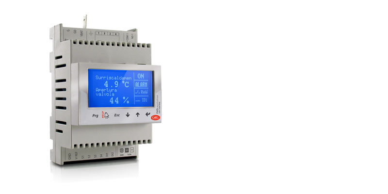
Драйверы электронных ТРВ серии EVD Evolution — это новейшие драйверы последнего поколения, выпускаемые компанией CAREL для регулирования перегрева.
В отличие от обычных драйверов EVD они поддерживают самые современные функции и получили новый графический терминал, который делает процесс настройки и работы с драйвером еще проще.
Драйвер настолько прост в настройке, что при наличии графического дисплея весь процесс ввода в эксплуатацию ограничивается настройкой буквально четырех параметров (или всего трех параметров, если драйвер будет управлять вентилями Carel): тип хладагента, тип вентиля, тип датчика давления и управляемый агрегат (холодильная машина, холодильная витрина и т.д.). Все параметры находятся в экранном меню драйвера.
Основные достоинства:
- регулирование перегрева и защита от недостаточного перегрева, низкого давления и высокого давления
- быстрый и простой ввод в эксплуатацию (достаточно настроить всего 4 параметра)
- схема соединений выводится на дисплее драйвера
- съемный жидкокристаллический дисплей, поддерживающий многоязычный интерфейс, справку по настройке параметров, единицы измерения СИ и британские
- разграничение уровней доступа паролями
- копирование параметров конфигурации с одного драйвера семейства EVD на другой (в памяти дисплея)
- светодиодные индикаторы для контроля основных параметров
- поддержка малопотребляющих логометрических датчиков давления со встроенным преобразователем и выходным сигналом тока 4 — 20мА (один датчик может использоваться несколькими драйверами)
- второй цифровой вход для управления оттайкой
- поддержка резервных датчиков
Драйверы EVD Evolution в сочетании с электронными терморасширительными вентилями CAREL семейства ExV представляют собой готовую интегрированную систему управления для обеспечения оптимальной работы испарителей и сокращения расходов на электроэнергию.
Документация
Technical
-
2D/3D модели
Код Описание Язык Дата * Выпуск Код
EVD Evolution Single.zipОписание
2D-3D drawingsЯзык
ALLДата
17/03/2023
Выпуск
R0
Код
EVD Evolution Single w Display.zipОписание
2D-3D drawingsЯзык
ALLДата
09/03/2023
Выпуск
R0
-
Инструкции по применению
Код Описание Язык Дата * Выпуск Код
+0300005DEОписание
EVD evolution
Treiber für elektronisches ExpansionsventilЯзык
GERДата
16/02/2023
Выпуск
4.0
Код
+0300005ENОписание
EVD evolution
electronic expansion valve driverЯзык
ENGДата
16/02/2023
Выпуск
4.0
Код
+0300005ESОписание
EVD evolution
driver para válvula de expansión electrónicaЯзык
SPAДата
16/02/2023
Выпуск
4.0
Код
+0300005FRОписание
EVD evolution
pilote pour vanne d’expansion électroniqueЯзык
FREДата
16/02/2023
Выпуск
4.0
Код
+0300005ITОписание
EVD evolution
driver per valvola di espansione elettronicaЯзык
ITAДата
16/02/2023
Выпуск
4.0
Код
+0300005PTОписание
EVD evolution
driver para válvula de expansão eletrônicaЯзык
PORДата
16/02/2023
Выпуск
4.0
Код
+0300005RUОписание
EVD evolution
Привод электронного расширительного вентиляЯзык
RUSДата
16/02/2023
Выпуск
4.0
Код
+0300005CSОписание
EVD evolution
Ovladač elektronického expanzního ventiluЯзык
CZEДата
16/02/2023
Выпуск
4.0
Код
+0300005JAОписание
EVD evolution
電子膨張弁ドライバーЯзык
JAPДата
16/08/2013
Выпуск
3.3
-
Руководства по эксплуатации
Код Описание Язык Дата * Выпуск Код
+050004150Описание
EVD*, EVDIS* — EVD evolution — Driver per valvola di espansione elettronica e display grafi co/ Electronic expansion valve driver and graphic displayЯзык
ENG
FRE
ITA
SPAДата
13/02/2023
Выпуск
3.0
Код
+050004151Описание
EVD*, EVDIS* — EVD evolution — Electronic expansion valve driver and graphic displayЯзык
CHI
GER
POR
RUSДата
13/02/2023
Выпуск
3.0
Commercial
-
Other related documentation
Код Описание Язык Дата * Выпуск Код
+800004030Описание
Soluzioni per Unità Trattamento Aria: Tecnologia e competenza per la qualità dell’aria e il risparmio energeticoЯзык
ITAДата
05/04/2023
Выпуск
1.2
Код
+800004031Описание
Solutions for Air Handling Units: Technology and expertise for indoor air quality and energy savingЯзык
ENGДата
05/04/2023
Выпуск
1.2
Images
-
High resolution images
Код Описание Язык Дата * Выпуск Код
PH08LEV301-EVD-evo-singleОписание
CAREL EVD Evolution — Expansion valve driver — EEV TechnologyЯзык
ALLДата
11/03/2022
Выпуск
R.0
-
Contents
-
Table of Contents
-
Troubleshooting
-
Bookmarks
Quick Links
Related Manuals for Carel EVD evolution
Summary of Contents for Carel EVD evolution
-
Page 2
EVD evolution electronic expansion valve driver User manual I n t e g r a t e d C o n t r o l S o l u t i o n s & E n e r g y S a v i n g s… -
Page 4
The technical specifications shown in the manual may be changed without prior warning. The liability of CAREL in relation to its products is specified in the CAREL general contract conditions, available on the website www.carel.com and/or by specific agreements with customers; specifically, to the extent where allowed… -
Page 6: Table Of Contents
9.6 pLAN error alarm ………………40 9.7 LAN error alarm (for tLAN and RS485/Modbus® driver) ….40 10. TROUBLESHOOTING 11. TECHNICAL SPECIFICATIONS 12. APPENDIX: VPM (VISUAL PARAMETER MANAGER) 12.1 Installation ………………..44 12.2 Programming (VPM) ………………44 “EVD evolution” +030222041 — rel. 1.0 — 01.06.2008…
-
Page 8: Introduction
Another possibility involves operation as a simple positioner with 4 to 20 mA or 0 to 10 Vdc analogue input signal. EVD evolution comes with a LED board to indicate the operating status, or a graphic display (accessory) that…
-
Page 9
Valve cable E2VCABS*00 (IP67) Shielded cable with built-in connector for connection to the valve motor. The connector code E2VCON0000 (IP65) can also be purchased on its own, to be wired. Fig. 1.d “EVD evolution” +030222041 — rel. 1.0 — 01.06.2008… -
Page 10: Installation
INSTALLATION DIN rail assembly and dimensions Connection diagram — superheat control EVD evolution is supplied with screen-printed connectors to simplify wiring. The shield is connected with a spade terminal. CAREL E Power Supply V connection Relay evolution shield 230 Vac…
-
Page 11: Installation
• strong vibrations or knocks; and display fi rmware, downloadable from http://ksa.carel.com. • exposure to continuous water sprays; See appendix 1. • exposure to aggressive and polluting atmospheres (e.g.: sulphur “EVD evolution” +030222041 — rel. 1.0 — 01.06.2008…
-
Page 12: Upload, Download And Reset Parameters (Display)
DO NOT remove the display from the driver during the UPLOAD, DOWNLOAD, RESET procedure; • the parameters cannot be downloaded if the source driver and the target driver have incompatible fi rmware. “EVD evolution” +030222041 — rel. 1.0 — 01.06.2008…
-
Page 13: General Connection Diagram
The maximum length of the connection cable to the EVBAT200/300 module is 5 m. solenoid valve alarm signal The connection cable to the valve motor must be 4-wire shielded, AWG 18/22 Lmax= 10 m black blue supervision computer “EVD evolution” +030222041 — rel. 1.0 — 01.06.2008…
-
Page 14: User Interface
UP/DOWN: the variables are shown on the display; press Esc to exit display mode. “EVD evolution” +030222041 — rel. 1.0 — 01.06.2008…
-
Page 15: Programming Mode (Display)
Confi guration Sensors Control Special Alarm confi guration Valve press the UP/DOWN buttons to select the category and ENTER to access the fi rst parameter in the category; “EVD evolution” +030222041 — rel. 1.0 — 01.06.2008…
-
Page 16: Commissioning
Then the driver will be enabled for control, and it will be possible to enter Manufacturer programming mode and set the corresponding parameters manually. “EVD evolution” +030222041 — rel. 1.0 — 01.06.2008…
-
Page 17
S2 is set as “CAREL NTC”. Other types of sensors can be Parameter/description Def. -
Page 18: Checks After Commissioning
• set, if necessary, in Service or Manufacturer programming mode, the superheat set point (otherwise keep the value recommended by CAREL based on the application) and the protection thresholds (LOP, MOP, etc.). See the chapter on Protectors. Other functions By entering Service programming mode, other types of main control can be selected (transcritical CO , hot gas bypass, etc.), as well as so-called…
-
Page 19: Control
“Backup sensors on S3 & S4” can always be activated, once the related sensors have been connected. The following paragraphs explain all the types of control that can be set on EVD evolution. evolution Fig. 5.a “EVD evolution” +030222041 — rel. 1.0 — 01.06.2008…
-
Page 20: Special Control
Note: when selecting the type of main control (both superheat pressure set point”. Control is direct, as the pressure increases, the valve control and special modes), the PID control values suggested by CAREL opens and vice-versa. will be automatically set for each application.
-
Page 21
PID: integration time Parameter/description Def. Min. Max. CONTROL Tab. 5.g Hot gas bypass pressure set point barg (290) (2900) (psig) PID: proportional gain PID: integration time 1000 PID: derivative time Tab. 5.f “EVD evolution” +030222041 — rel. 1.0 — 01.06.2008… -
Page 22
CONTROL PID: proportional gain Important: the pre-positioning and repositioning procedures PID: derivative time 1000 are not performed. Manual positioning can be enabled when control is PID: integration time active or in standby. “EVD evolution” +030222041 — rel. 1.0 — 01.06.2008… -
Page 23: Auxiliary Control
S4, located in a similar position to the one used for the traditional temperature control of the cabinet. In practice, the close the controlled temperature gets to the set point, the more the control “EVD evolution” +030222041 — rel. 1.0 — 01.06.2008…
-
Page 24
Fig. 5.j Key: Compressor EEV Electronic expansion valve Condenser Solenoid valve Liquid receiver Evaporator Dewatering filter Pressure sensor (transducer) Liquid indicator Temperature sensor For the wiring, see paragraph 2.7 “General connection diagram”. “EVD evolution” +030222041 — rel. 1.0 — 01.06.2008… -
Page 25: Functions
Fig. 6.a Parameter/description Def. CONFIGURATION Sensor S2: CAREL NTC Key: CAREL NTC; CAREL NTC-HT high T; Combined NTC SPKP**T0; A= offset, 0-10 V external signal B= gain Sensor S4: CAREL NTC CAREL NTC; CAREL NTC-HT high T; Combined NTC SPKP**T0 Tab.
-
Page 26: Control Status
If during standby a control request is received, before starting control the valve is moved to a precise initial position. Parameter/description Def. Min. Max. Control Valve opening at start (evaporator/valve capacity ratio) Tab. 6.i “EVD evolution” +030222041 — rel. 1.0 — 01.06.2008…
-
Page 27: Special Control Status
Manufacturer programming mode, under the configuration Change capacity Wait parameters, set the PID proportional gain= 0. The valve will remain NP Repositioning Time stopped at the initial opening position, set by corresponding Control parameter. “EVD evolution” +030222041 — rel. 1.0 — 01.06.2008…
-
Page 28
Note: the valve unblock procedure is nonetheless performed in each of these cases, given that it does not cause mechanical or control problems. Therefore, also check these possible causes before replacing the valve. “EVD evolution” +030222041 — rel. 1.0 — 01.06.2008… -
Page 29: Protectors
(LowSH) (0= alarm disabled) exactly half-way between the two limits indicated; Tab. 7.b • the protector has no purpose in multiplexed systems (showcases) where the evaporation is kept constant and the status of the individual “EVD evolution” +030222041 — rel. 1.0 — 01.06.2008…
-
Page 30
As the action is integral, it depends directly on where the condensing pressure is maintained constant and the status the difference between the evaporation temperature and the activation of the individual electronic valves does not affect the pressure value. “EVD evolution” +030222041 — rel. 1.0 — 01.06.2008… -
Page 31
• the closing of the valve will be limited if this causes an excessive decrease in the evaporation temperature. “EVD evolution” +030222041 — rel. 1.0 — 01.06.2008… -
Page 32: Parameters Table
CAREL NTC-HT high temp. Combined NTC SPKP**T0 0 to 10 V external signal Auxiliary control: Disabled Disabled High condensing temperature protection on S3 Modulating thermostat on S4 Backup sensors on S3 & S4 “EVD evolution” +030222041 — rel. 1.0 — 01.06.2008…
-
Page 33
Valve in fixed position Sensor S4 alarm management: No action No action Forced valve closing Valve in fixed position Language: Italiano; English Italiano Unit of measure: °C(K), barg; °F(°R), psig °C(K), barg “EVD evolution” +030222041 — rel. 1.0 — 01.06.2008… -
Page 34
°C (°F) Modulating thermostat: differential 0, 1 0, 1 (0,2) 100 (180) °C (°F) Modulating thermostat: superheat set point offset 0 (0) 100 (180) K (°R) Coefficient ‘A’ for CO control -100 “EVD evolution” +030222041 — rel. 1.0 — 01.06.2008… -
Page 35: Unit Of Measure
Note: because of some internal arithmetics limitations of the driver, it will not be possible to convert the pressure values higher than 200 barg (2900 psig) and the temperature values higher than 200 °C (392 °F). “EVD evolution” +030222041 — rel. 1.0 — 01.06.2008…
-
Page 36: Variables Shown On The Display
-20 (-290) 200 (2900) 4 to 20 mA input value 0 to 10 V input value Control set point -60 (-76) 200 (392) Driver firmware version Valve position 9999 Current unit cooling capacity “EVD evolution” +030222041 — rel. 1.0 — 01.06.2008…
-
Page 37
Enable EVD control Tab. 8.c Type of variable: A= analogue, D= digital, I= integer SVP= variable address with CAREL protocol on 485 serial card. Modbus®: variable address with Modbus® protocol on 485 serial card. “EVD evolution” +030222041 — rel. 1.0 — 01.06.2008… -
Page 38: Alarms
) parameter Low suction Threshold and de- ALARM fl ashing Depends on automatic No eff ect Check the threshold and delay temperature lay time exceeded confi guration parameters. parameter “EVD evolution” +030222041 — rel. 1.0 — 01.06.2008…
-
Page 39: Alarm Relay Configuration
• by default, after having selected the type of sensor used, the alarm limits will be automatically set to the limits corresponding to the range of measurement of the sensor. “EVD evolution” +030222041 — rel. 1.0 — 01.06.2008…
-
Page 40: Control Alarms
If the delay relating to the control alarms is set to 0 s, the alarm is disabled. The protectors are still active, however. The alarms are reset automatically. “EVD evolution” +030222041 — rel. 1.0 — 01.06.2008…
-
Page 41: Plan Error Alarm
The green NET LED will however indicate any problems in the line. The NET LED flashing or off indicates the problem has lasted more than 150 s. “EVD evolution” +030222041 — rel. 1.0 — 01.06.2008…
-
Page 42: Troubleshooting
Apply a “soft start” technique, activating the utilities one at a time or in small groups. If or extreme transitory conditions at start-up this is not possible, decrease the values of the MOP thresholds on all the utilities. (for cabinets only). “EVD evolution” +030222041 — rel. 1.0 — 01.06.2008…
-
Page 43
Check the connection of the digital input. Check that when the control signal is sent cabinets only) does not start control and the valve that the input is closed correctly. Check that the driver is in stand-alone mode. remains closed Tab. 10.a “EVD evolution” +030222041 — rel. 1.0 — 01.06.2008… -
Page 44: Technical Specifications
Class of insulation Software class and structure Conformity : EN 60730-1, EN 61010-1 Electrical safety y: EN 61000-6-1, EN 61000-6-2, EN 61000-6-3, EN 61000-6-4; EN61000-3-2, EN55014-1, Electromagnetic compatibilit EN55014-2, EN61000-3-3. Tab. 11.a “EVD evolution” +030222041 — rel. 1.0 — 01.06.2008…
-
Page 45: Appendix: Vpm (Visual Parameter Manager)
When opening the program, the user needs to choose the device being Fig. 12.c confi gured: EVD evolution. The Home page then opens, with the choice to create a new project or open an existing project. Choose new project select the model from the range and create a new project or and enter the password, which when accessed the fi…
-
Page 46: Copying The Setup
USB/tLAN converter, which is connected to the device being programmed (see paragraph 2.5 for the connection diagram). The fi rmware can be downloaded from http://ksa.carel.com. See the VPM On-line help. “EVD evolution” +030222041 — rel. 1.0 — 01.06.2008…
-
Page 47
“EVD evolution” +030222041 — rel. 1.0 — 01.06.2008… -
Page 49
Agenzia / Agency: CAREL S.p.A. Via dell’Industria, 11 — 35020 Brugine — Padova (Italy) Tel. (+39) 049.9716611 — Fax (+39) 049.9716600 e-mail: carel@carel.com — www.carel.com…